Falcon RU-Series Retrofit Extra Heavy Duty Unit Lever Lockset Installation Instructions – English 106830
Open the original PDF document
View PDFMARK DOOR
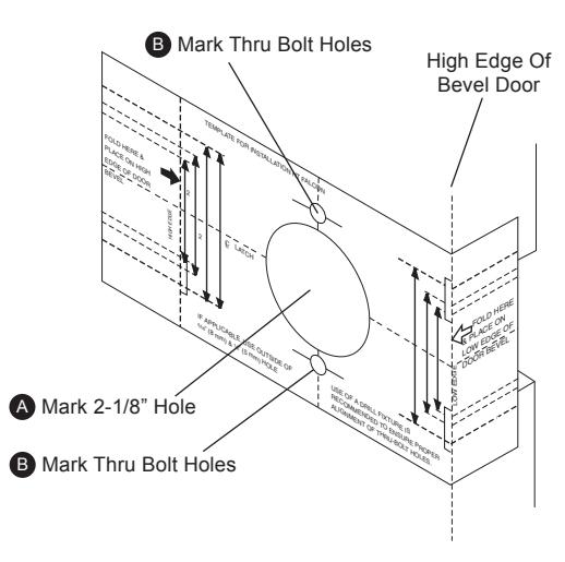
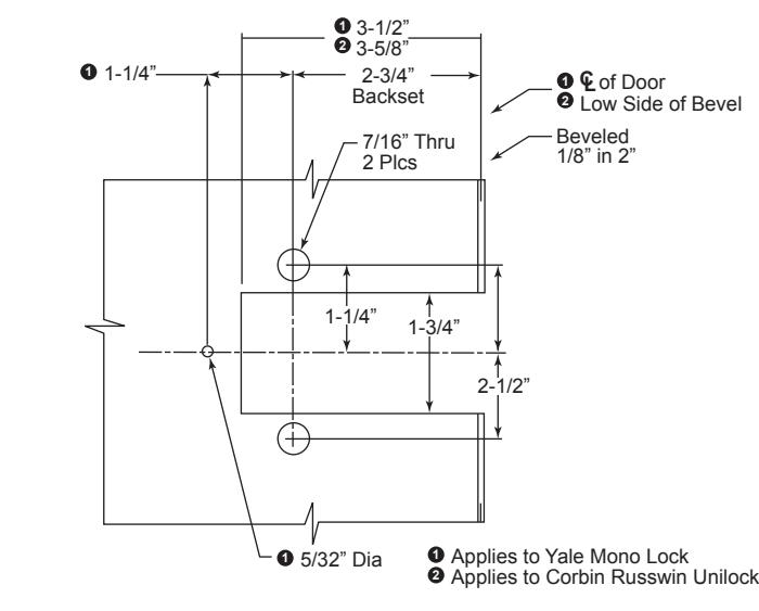
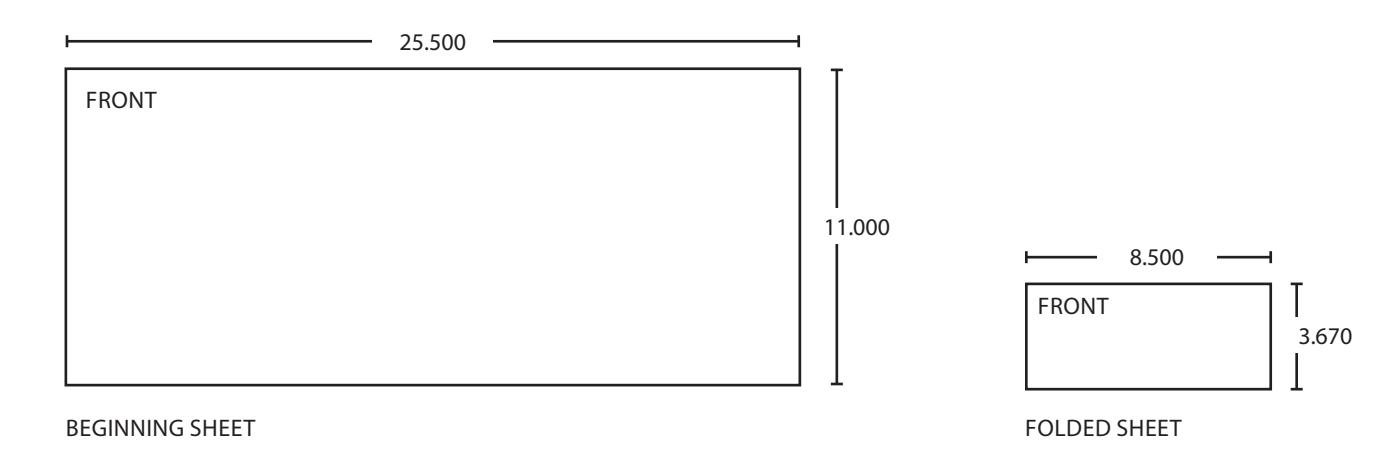
Fold template on lines indicated. Place on HIGH EDGE of door bevel.
- A. Place template on high edge of door bevel. Center the template to the slot opening and mark 2-1/8" diameter on surface of door. Repeat same for low edge of door.
- B. Locate and verify clearance for two (2) 5/16" (8mm) thru-bolt holes.
STEP 3 BORE HOLE
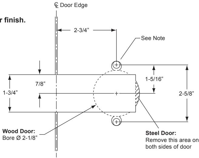
When drilling through door, be careful not to damage the door finish.
- A. For wood doors : Using a standard commercial boring jig bore the 2-1/8" (54mm) hole. Drill from both side of door to avoid splintering wood.
- B. For steel doors : Grind off the marked area to provide clearance for the chassis housing.
Note: In most cases the chassis mounting posts will fit through the existing holes in the door.
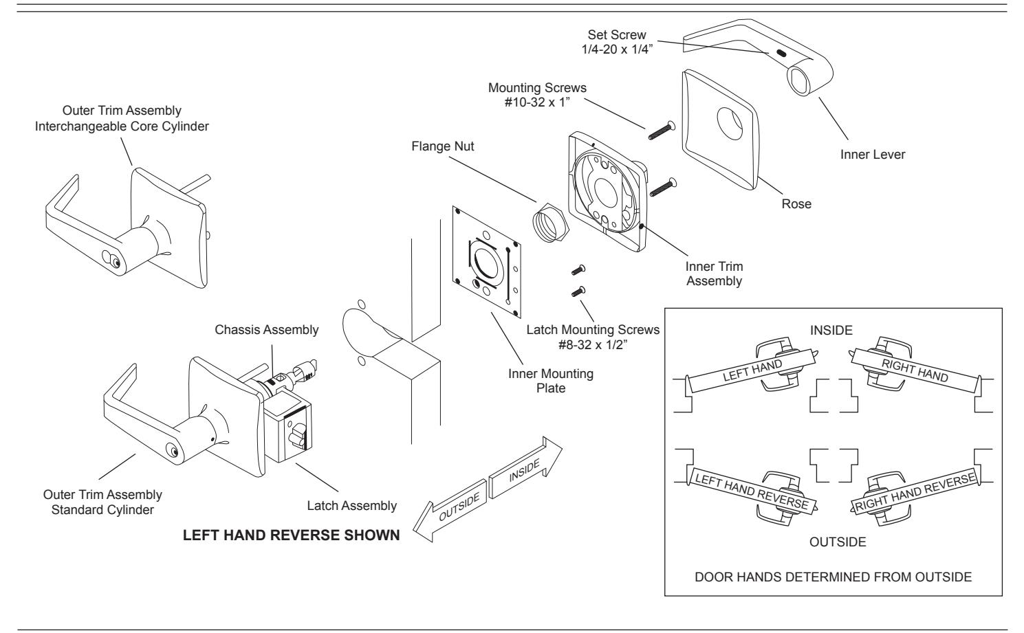
STEP 4 INSTALL TRIM AND CHASSIS ASSEMBLY
Slide trim and chassis assembly into door from outside.
Important: Chassis assembly must be positioned in center of door for proper operation.
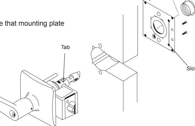
STEP 5 INSTALL INNER MOUNTING PLATE
- A. Place inner mounting plate onto chassis assembly making sure that mounting plate slot and latch adapter tab are fully engaged.
- B. Secure mounting plate to latch adapter with the two #8-32 x 1/2" flat head screws supplied.
- Position flanged nut over chassis assembly and tighten securely with black hex wrench provided.
- Optional: Secure mounting plate to door with two #8 x 3/4" Phillips Pan head self-drilling sheet metal screws or equivalent (not supplied).
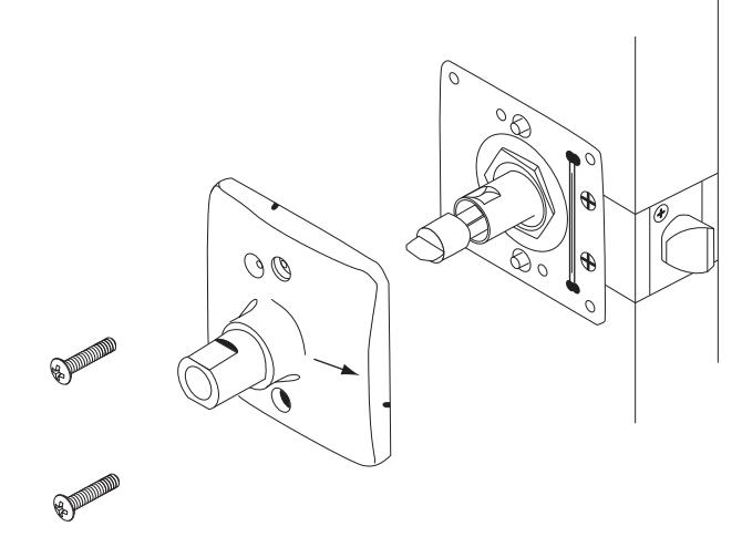
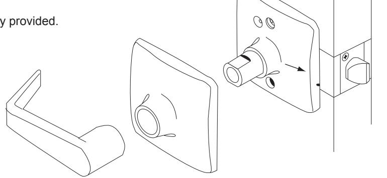
STEP 6 INSTALL INNER TRIM ASSEMBLY
Position inner trim assembly with arrow towards door edge and slide onto chassis spindle. Thru-posts will engage inner trim assembly. Secure to door with the two #10-32 x 1" screws provided.
STEP 7 INSTALL INNER LEVER
- A. Position rose over inner trim assembly.
- B. Install lever handle and tighten set screw with hex key provided.
Stop! Test operation to be sure latch bolt moves freely. Do not force . If lockset does not operate properly, re-move lockset from door and check door preparation. See Step 4 to re-install chassis.
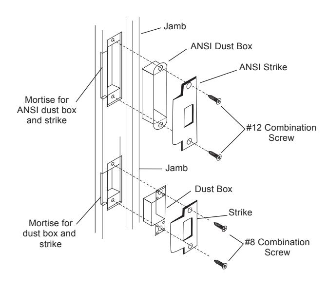
STEP 8 LOCATE AND INSTALL STRIKE
- A. Remove old strike and install new strike and dust box.
- B. Close door and check for proper operation.
Caution: Deadlocking plunger of latch bolt must not enter opening in strike plate.
C. If latch operates improperly, or is excessively loose, contact factory for different strike configurations.
Note: It may be necessary to rework the door jamb for the dust box to fit properly.
Customer Service
1-877-671-7011 www.allegion.com/us
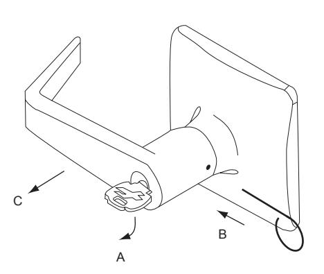
FEP 9 INSTRUCTIONS FOR REHANDING LOCK FOR DOOR BEVEL
- A. Temporarily, re-install latch assembly mounting screws (A) on the inside without the inside mounting plate (this is to hold the support plates in place during rehanding).
- B. Remove the outside trim retaining screw (B).
- C. Slide the outside trim (C) from the chassis assembly.
- D. Remove two (2) latch assembly mounting screws (D). IMPORTANT: DO NOT remove or adjust hex nut.
- Slide the latch assembly from the chassis. Replace the latch assembly mounting screws (D) finger tight.
- F. Reverse the latch assembly and remove the latch assembly screws (A), then place it on the chassis. Make sure that chassis housing engages the latch assembly. Retractor must also en-gage the latch tail.
- G. Replace the two (2) latch assembly mounting screws (A) making sure to align the tab of the latch assembly with the slot of the mounting plate and screw holes of the support plates.
- Slide the outside trim (C) onto the chassis.
- Replace the outside trim retaining screw (B).
- Remove latch assembly mounting screws (D). Do not discard!
- K. See Step 4 to continue.
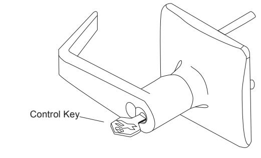
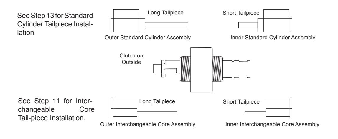
STEP 10 TO REMOVE INTERCHANGEABLE CORE CYLINDER LEVERS
- A. Insert control key into core and rotate 15 degrees clockwise. Pull key to remove core.
- B. Insert screwdriver into Figure "8" core hole and into lever retainer.
- C. Depress retainer and slide lever off spindle.
TO RE-INSTALL LEVER
- Slide lever over spindle and push on over retainer.
- E. Give a pull on lever to be sure retainer engaged lever.
- F. Re-install core with tailpiece pushed into core.
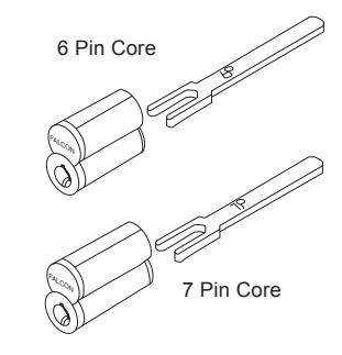
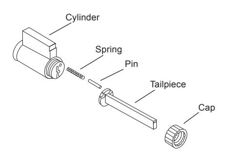
STEP 11 INTERCHANGEABLE CORE CYLINDER TAILPIECE INSTALLATION
For proper function of the lock the right tailpiece must be used. Six pin cores should only use the "6P" tailpiece and seven pin core should only use the "7P" tailpiece.
STEP 12 TO REMOVE STANDARD CYLINDER LEVERS
- Insert key and rotate clockwise approximately 60 degrees.
- B. Depress lever retainer with tool provided.
- C. Slide lever off spindle.
TO RE-INSTALL LEVER
- D. Insert cylinder into spindle.
- E. Slide lever onto spindle.
- F. Insert key into cylinder and rotate clockwise approximately 60 degrees and push lever over retainer.
- G. Give a pull on lever to be sure retainer engaged lever.
STEP 13 STANDARD CYLINDER TAILPIECE INSTALLATION
For proper function of the lock the right tailpiece must be used and must be installed correctly. All RU-Series locks with standard cylinders must have the tailpiece installed vertically on the cylinder as shown.
The cap must be properly adjusted. If too loose, excessive plug end play will prevent the key from being withdrawn. If too tight, the plug will drag and be difficult to rotate with the key.
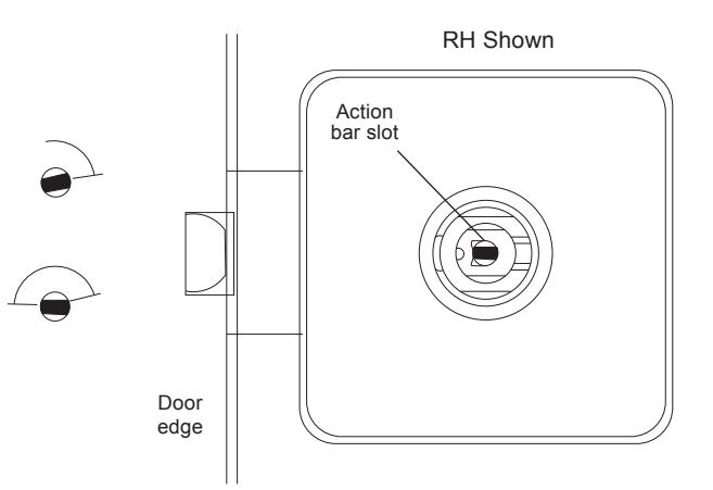
STEP 14 TIMING INSTRUCTIONS FOR STANDARD CYLINDER LOCKS For The Following Functions: RU371, RU381, RU561, RU571
- A. If the cylinder & handle are installed, refer to step 12 for lever
- B. Using a thin flat screw driver, turn the action bar slot clock-
- C. Then turn the action bar counterclockwise (ccw) to the 9:00 position. There is no physical stop at this location.
- D. With the key out, install standard cylinder into the spindle.
- E. Refer to step 12 for lever installation instructions.
wise (cw) until it stops at about 2:00.
Operate key to test for proper operation
removal instrucitons.
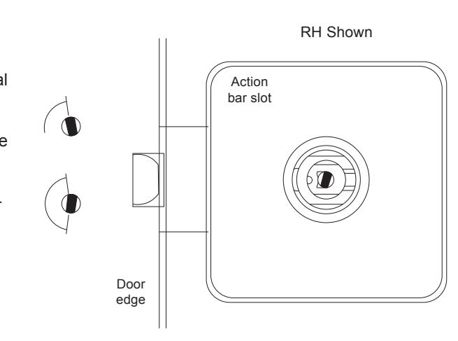
STEP 15 TIMING INSTRUCTIONS FOR IC CYLINDER LOCKS
For The Following Functions: RU371, RU381, RU561, RU571
- A. If the cylinder is installed, refer to step 10 for IC core removal instructions.
- B. Using a thin flat screw driver, turn the action bar slot clockwise (cw) until it stops at about 11:00.
- C. Then turn the action bar counterclockwise (ccw) to the 7:00 position. There is no physical stop at this location
- D. Using the control key, insert IC core into the lever and spindle.
- E. Remove control key.
- F. Operate key to test for proper operation.
STEP 16 TAILPIECE INSTALLATION INSTRUCTIONS FOR RU381 FUNCTION

© Allegion 2014 Printed in U.S.A. 031534 Rev. 01/14-d

RU-Series
FALCON <sub>®</sub>
031534
Retrofit Extra Heavy Duty Unit Lever Lockset
Installation Instructions
IMPORTANT: THIS LOCK IS FOR 1-3/4" (45MM) THICK DOORS ONLY.
THE LOCK IS FACTORY HANDED FOR USE ON RIGHT HAND (RH) OR LEFT HAND (LH) DOORS. SEE STEP 9 FOR FIELD REVERSING THE LOCK TO RHR OR LHR DOORS. FOR FUNCTIONS RU371, RU381, RU561 & RU571, SEE STEP 14 FOR STD CYLINDER & STEP 15 FOR IC CORE TIMING INSTRUCTIONS.
STEP 1 EXAMINE DOOR PREPARATION AND HANDING
These instructions are applicable to the two most common door preparations – Yale Mono Lock and Corbin Russwin Unilock – as shown in the illustration on the right. If your door preparation is different, Stop! You need to contact the factory for instructions specifically for your door preparation.
STOP! Ensure that the lock handing matches the door handing and bevel. If it does not match, refer to Step 9 before continuing.
| Additional Notes: | ||
|---|---|---|
| 1. None | ||
| Revision History | Revision Description: | |||||||||
|---|---|---|---|---|---|---|---|---|---|---|
| Α | В | С | D | E | F | D > Revised artwork | ||||
| N/A | 0790 | 6683 | ||||||||
| Material | Material White Paper | Edited By | Approved By | EC Number | Release Date | |||||
| D. Spence | M. Sasso | 043528 | 01-01-14 | |||||||
| Notes | Notes | Title | ||||||||
|
Installation Inst RU Lock | |||||||||
| 3. tolerance ± .13 | Creation Date | Number | Revision | |||||||
|
01-08-14 | 031534 | D | |||||||
| J. diawii | 3. drawlings flot to scale |
Created By
D. Spence |
Activity
3899 Hancock Expwy |
|||||||
| Software: InDesign CS6 | Security, CO 80911 | © Allegion 2014 | ||||||||