Falcon MEL 24 25 Installation Instruction 113122
Open the original PDF document
View PDF

MEL 24/25 Series
Motorized Electric Latch Retraction
Installation Instructions

These instructions are for MEL conversion kits or MEL devices with preinstalled motors.
Parts
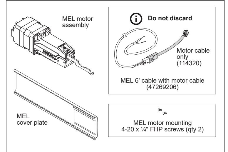
Allegion Connect accessories available to order
106198 MEL-CON adapter cable with 8-pin connector
040069 MEL motor cable + MEL-CON adapter cable with 8-pin
connector
If MEL is preinstalled in the device:
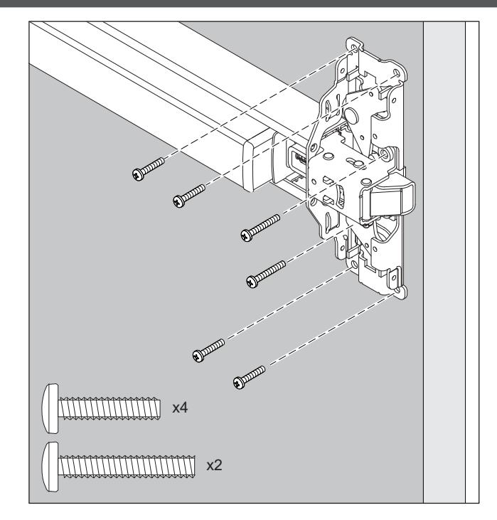
Follow original device instruction up to the point where this end mounting bracket step has been completed. A.
Mark and Prepare 2 Holes
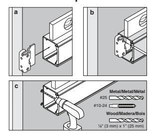
- Complete MEL wiring per steps 15-21 of this instruction. B.
- Return to original device instruction at point you left off, and complete installation. C.
- If installing the MEL conversion kit, follow the instruction steps as written.
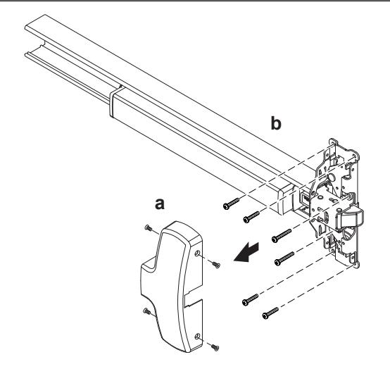
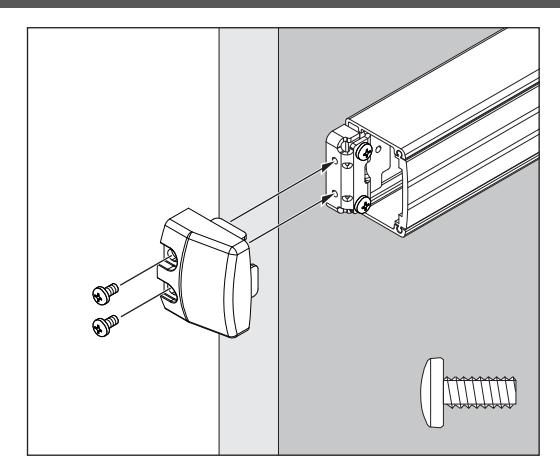
1 Remove end cap
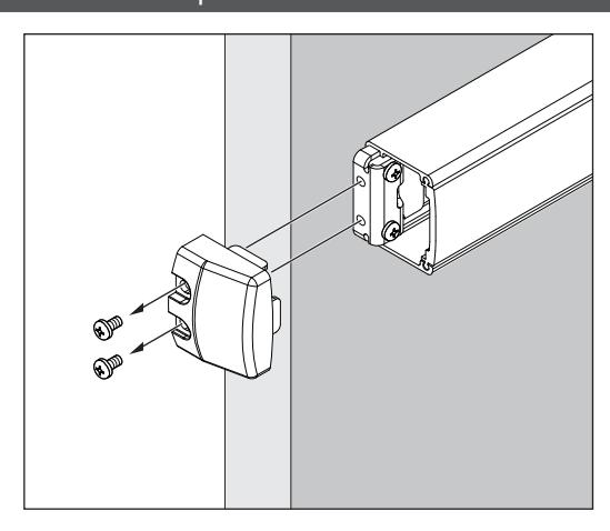
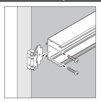
2 Remove device end mounting bracket from door
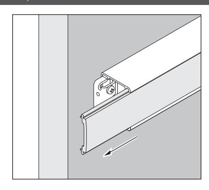
3 Slide back, remove and discard old cover plate
4 Remove center case cover and device from door
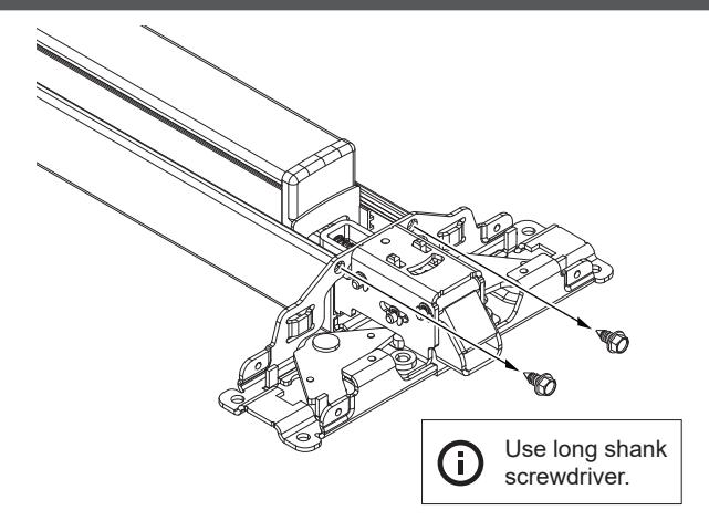
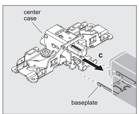
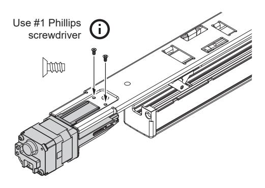
5 With device laying on a table or bench, remove the 2 screws that connect mechanism case to center case
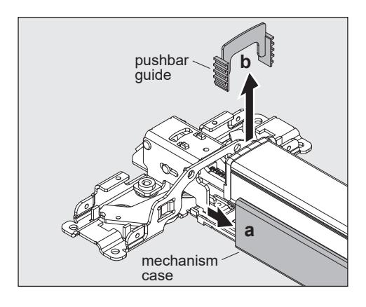
6 Unhook baseplate from center case
- a. Slide back mechanism case about 2" to access hooking parts.
- b. Push bar guides will come loose and will need to be reinstalled later.
- c. Unhook baseplate from center case.
9 Secure motor assembly
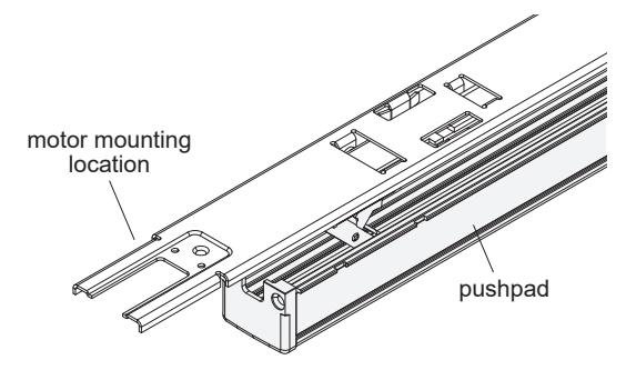
a. Turn baseplate assembly upside down so pushpad is resting on a flat surface and motor mounting location is on the left.
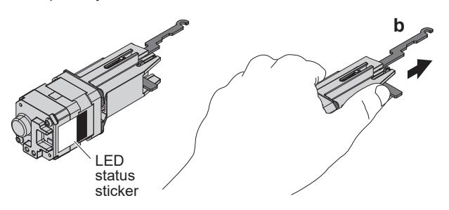
b. Place motor in left hand with LED status sticker facing toward you. Gently extend silver hook arm outward (about Z\x") until you meet some resistance, then hold.
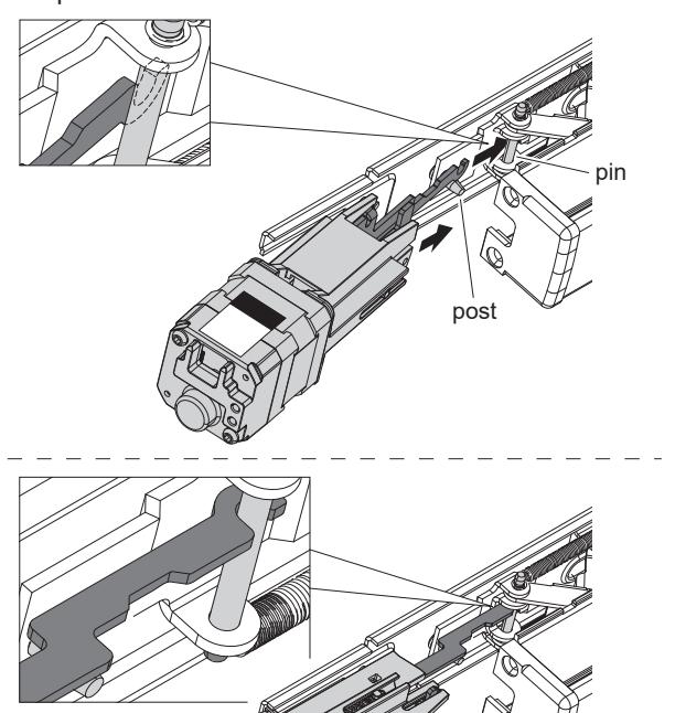
c. While tilting baseplate assembly away from you slightly, move extended hook arm into position under baseplate. A post will be hanging down from baseplate; the hook arm should sit on the near side of that post. Rotate the motor assembly to hook the arm over the baseplate axle pin that is closest to the baseplate. Do not pull out on motor at this step.
d. Set motor on flat surface.
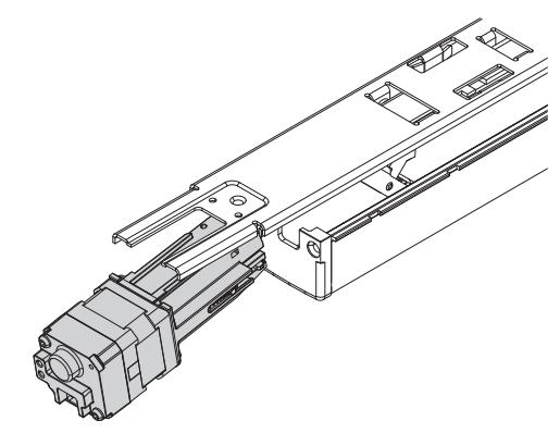
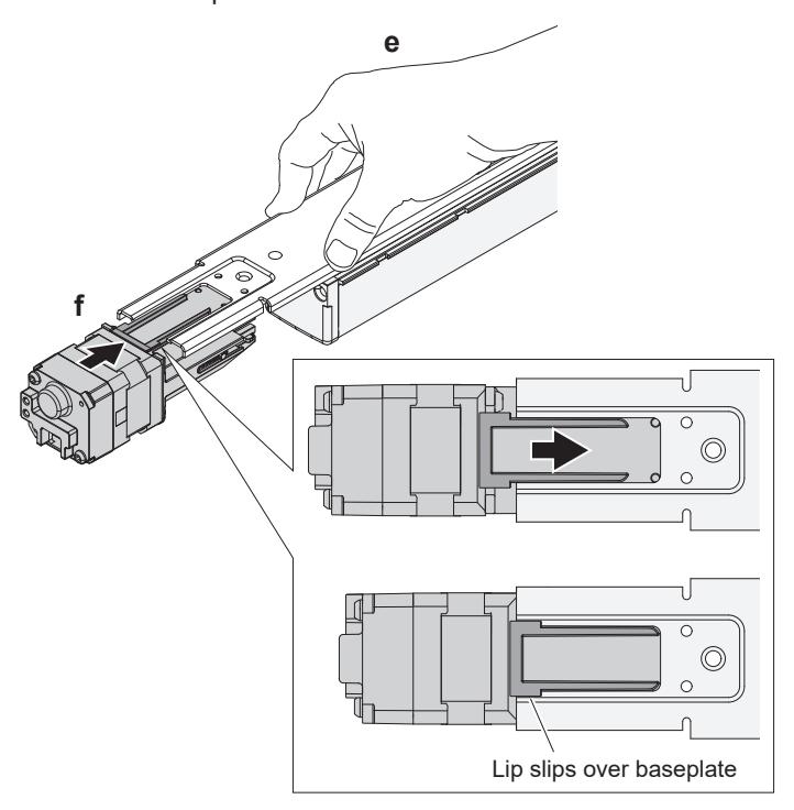
- e. Push down firmly on baseplate so it bottoms out against push pad.
- f. While depressing baseplate, lift up motor assembly and guide it along elongated baseplate slot until motor lip slips over baseplate.
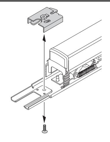
g. Release baseplate. Secure motor assembly with 2 small self-tapping screws (provided).
h. Turn baseplate and motor assembly right side up.
90°
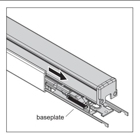
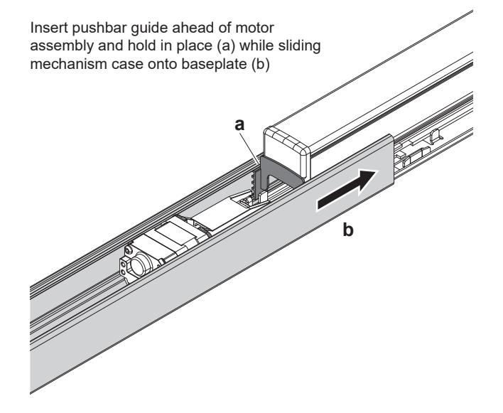
10 Slide mechanism case onto baseplate
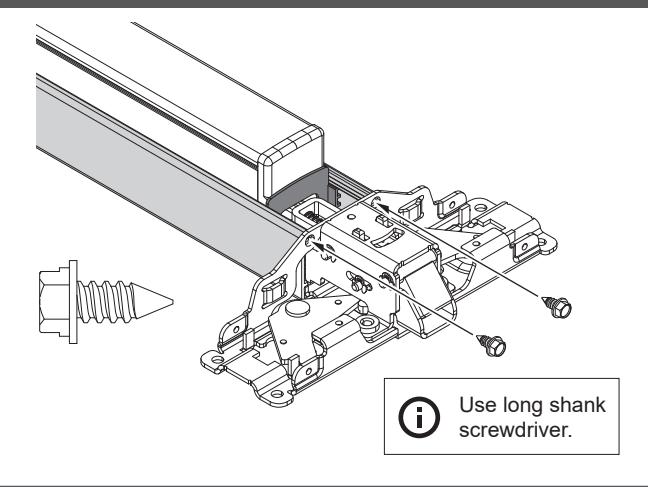
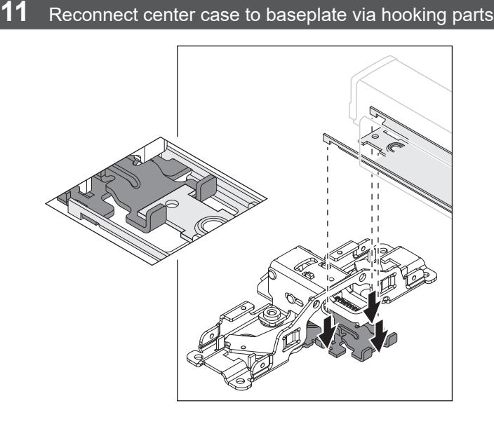
13 Reattach mechanism case to center case
14 Reattach device to door
12 Insert remaining pushbar guide (nearest the center case) and slide mechanism case against center case

15 Complete wiring

If not wiring at this time, DO NOT DISCARD CABLE!
After installing device or conversion kit, if there is room, store the cable inside the mechanism case until the electrical wiring occurs. Otherwise, store the cable in a designated location.
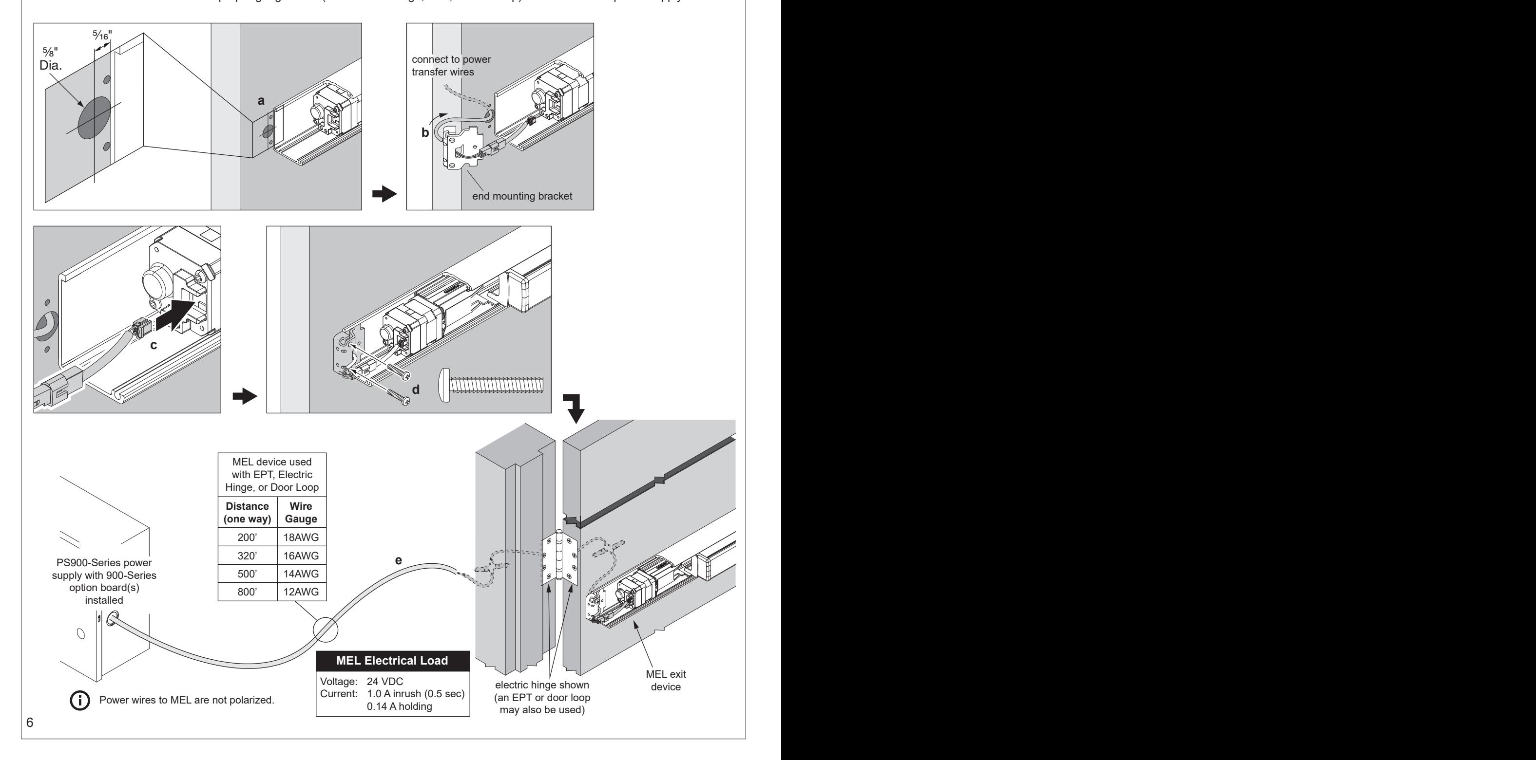
- a. Drill wire access hole.
- b. Route furnished 6' MEL two-piece cable thru device end mounting bracket to connect MEL device to power transfer wires.
- c. Plug cable connector into MEL motor.
- d. Reinstall end mounting bracket.
- e. Refer to table below to route proper gauge wires (from electric hinge, EPT, or door loop) to PS900-Series power supply.
MEL Wiring and Configuration (page 2 of 3)
WARNING
To avoid risk of electric shock, turn off AC power to power supply before installing or wiring option board.
16 Confirm equipment compatibility
MEL is compatible with the following equipment (refer to individual instructions as needed):
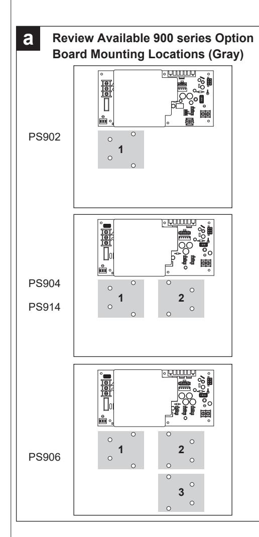
- PS900-Series power supplies PS902, PS904, PS906, PS914
- 900-Series option boards 900-2RS, 900-4R, 900-4RL
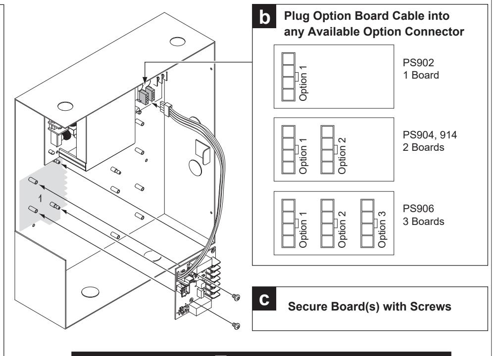
17 Install 900-2RS, 4R, or 4RL option board(s) into power supply
WARNING
Fire alarm (FA) option board required if MEL is installed in fire exit hardware.
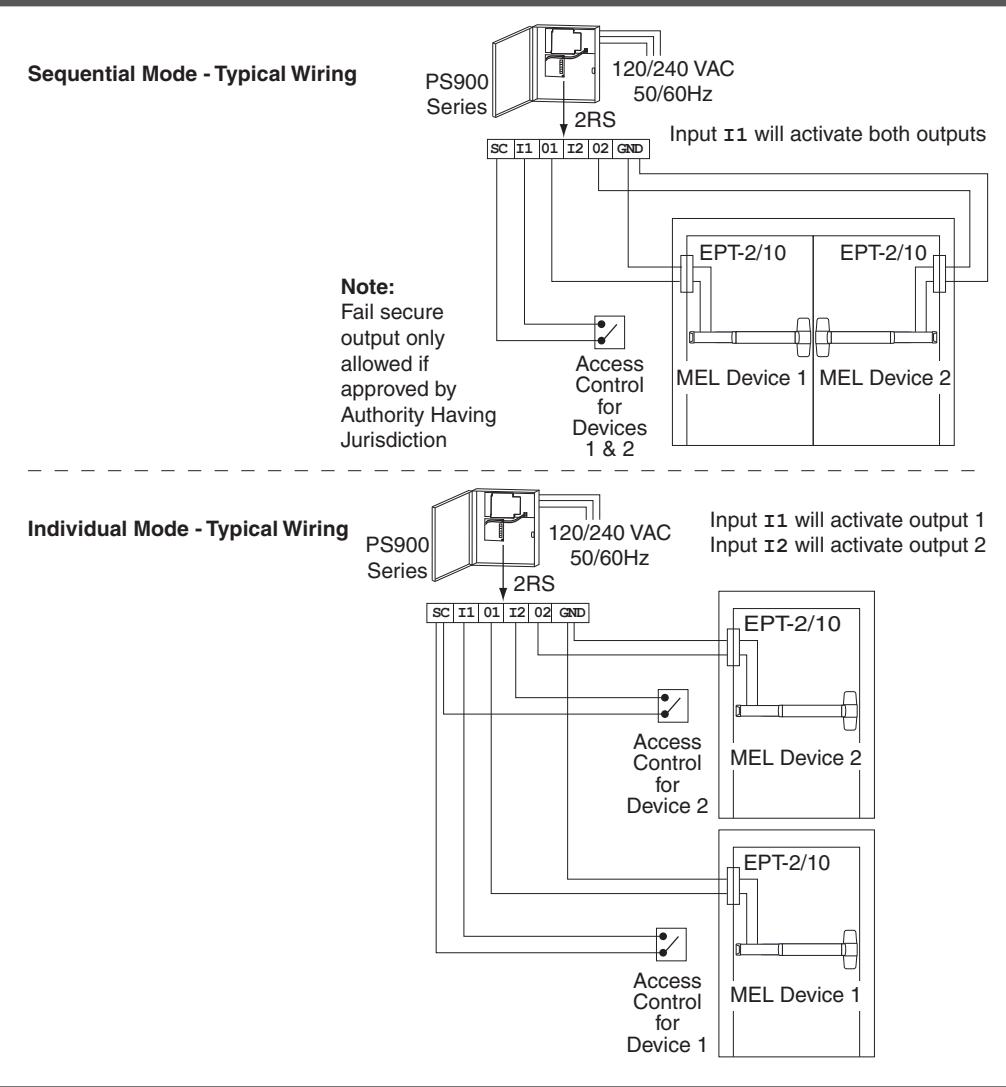
Notes: 1. 24 VDC output setting required when MEL device connected.
- 2. If installing board in location 2 or 3, rotate board 180°.
- 3. Latchbolt retraction of (2) sequenced MEL devices requires more than 1 second to complete.
- 4. When powering multiple components, verify that the amperage requirements of all components combined does not exceed the power supply output rating.
18 Connect input and output wires to option board (2RS shown)
19 Check operation
- a. Activate each input and verify all MEL devices operate properly.
- b. If any device does not operate properly, see next page for troubleshooting.
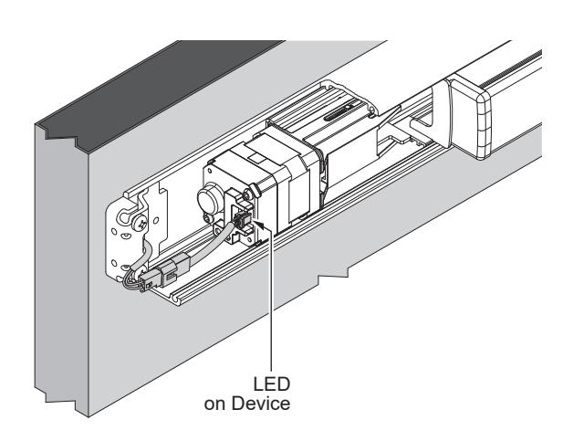
20 If necessary, troubleshoot operation (LED is only visible with the mechanism case removed)
|
Power at
the MEL |
MEL Response | Condition/Solution |
|---|---|---|
| 24 VDC |
LED - solid green
Latchbolt - retracted |
Operation normal, latch retracted immediately |
|
LED - solid red after latchbolt
attempts to retract multiple times |
Latchbolt cannot fully retract mechanically | |
|
Remove power. Depress pushbar and make sure
latchbolt retracts and extends fully. If necessary, disconnect any vertical rods or mortise lock from device center case, and reapply power. If motor holds, mechanical adjustments may be required per the device instructions.* |
||
|
LED - flashing green/red
Latchbolt - not retracted |
Excessive tamper (while power applied, the
pushpad was pulled out at least 3 times) |
|
|
Wait 15 seconds and latchbolt will retract again OR
remove and reapply power to clear condition. |
||
| 24 VDC low |
LED - flashing green
Latchbolt - retracted |
Voltage low during latchbolt retraction
(latchbolt retracts at reduced force) |
|
Wire length is too long, wire gauge is too small, or
power supply has poor regulation. |
||
|
29 VDC or
greater |
LED- flashing red
Latchbolt - will not retract |
Input voltage is too high for proper operation |
| Wrong power supply, power supply defective. | ||
|
13 VDC or
lower |
Input voltage is too low for proper operation | |
|
Wrong power supply, power supply defective or not
set to the proper output voltage. |
||
|
To set, remove AC power from power supply,
change power supply setting from 12 to 24 VDC, then reapply AC power and verify proper operation. |
||
| 0 VDC |
LED - off
Latchbolt - not retracted |
No input voltage |
|
Problem with the power supply, control switch, or
wiring. |
*For information about adjusting exit devices, you can find their installation instructions in the support area at www.allegion.com/us or call Technical Services at 1-877-671-7011
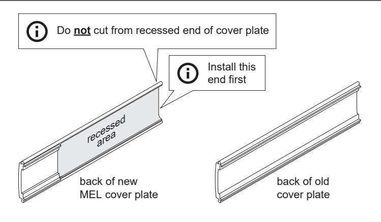
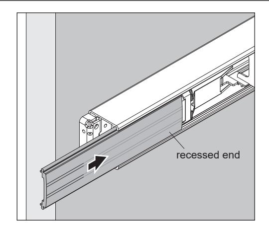
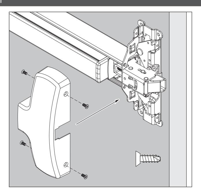
21 Install MEL cover plate
Reinstall end cap
Reinstall center case cover
Warnings and Cautions
Warnings look like this:
WARNING
Warnings indicate potentially hazardous conditions, which if not avoided or corrected, may cause death or serious injury.
Cautions look like this:
CAUTION
Cautions indicate potentially hazardous conditions, which if not avoided or corrected, may cause minor or moderate injury. Cautions may also warn against unsafe practices.
Notices look like this:

Notices indicate a condition that may cause equipment or property damage only.
Directions look like this:

Directions identify a step that may or may not apply to your product configuration. It also may direct you to another part of the instruction.