Falcon HH 1690 Concealed Vertical Rod Touchbar Panic Device Installation Instructions – English 110148
Open the original PDF document
View PDF

HH 1690
24187247
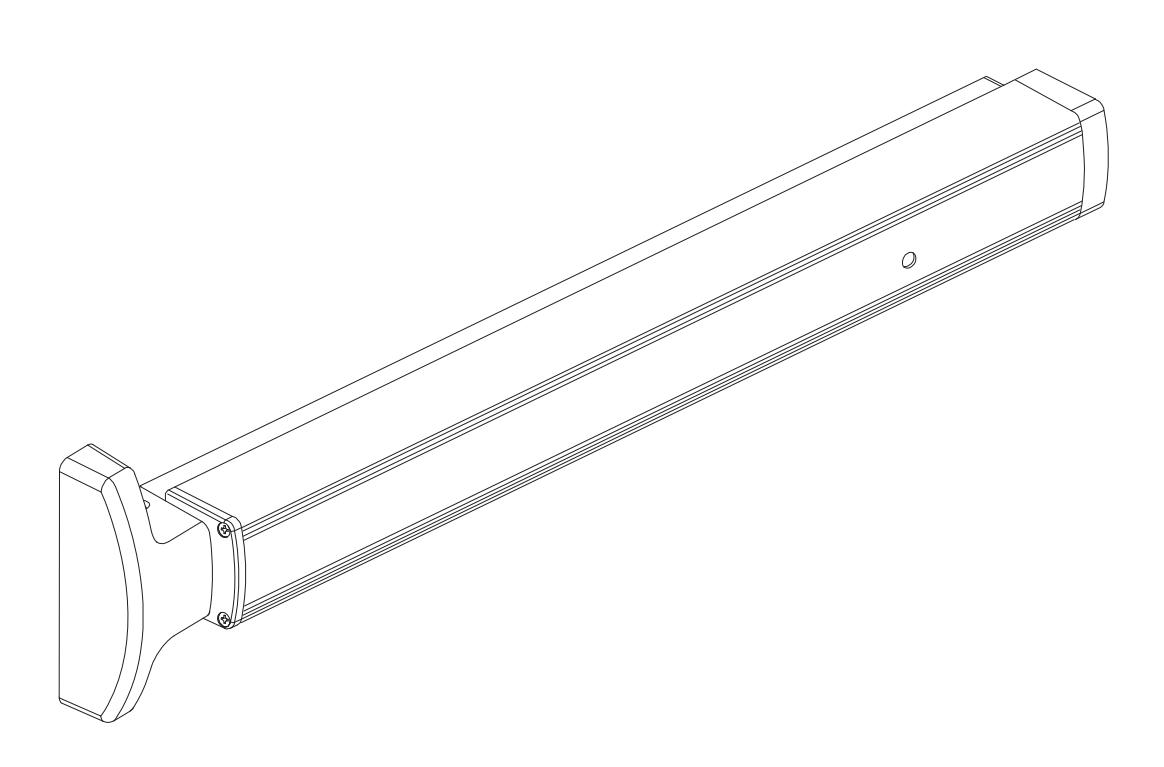
Concealed Vertical Rod Touchbar Panic Device
Installation Instructions
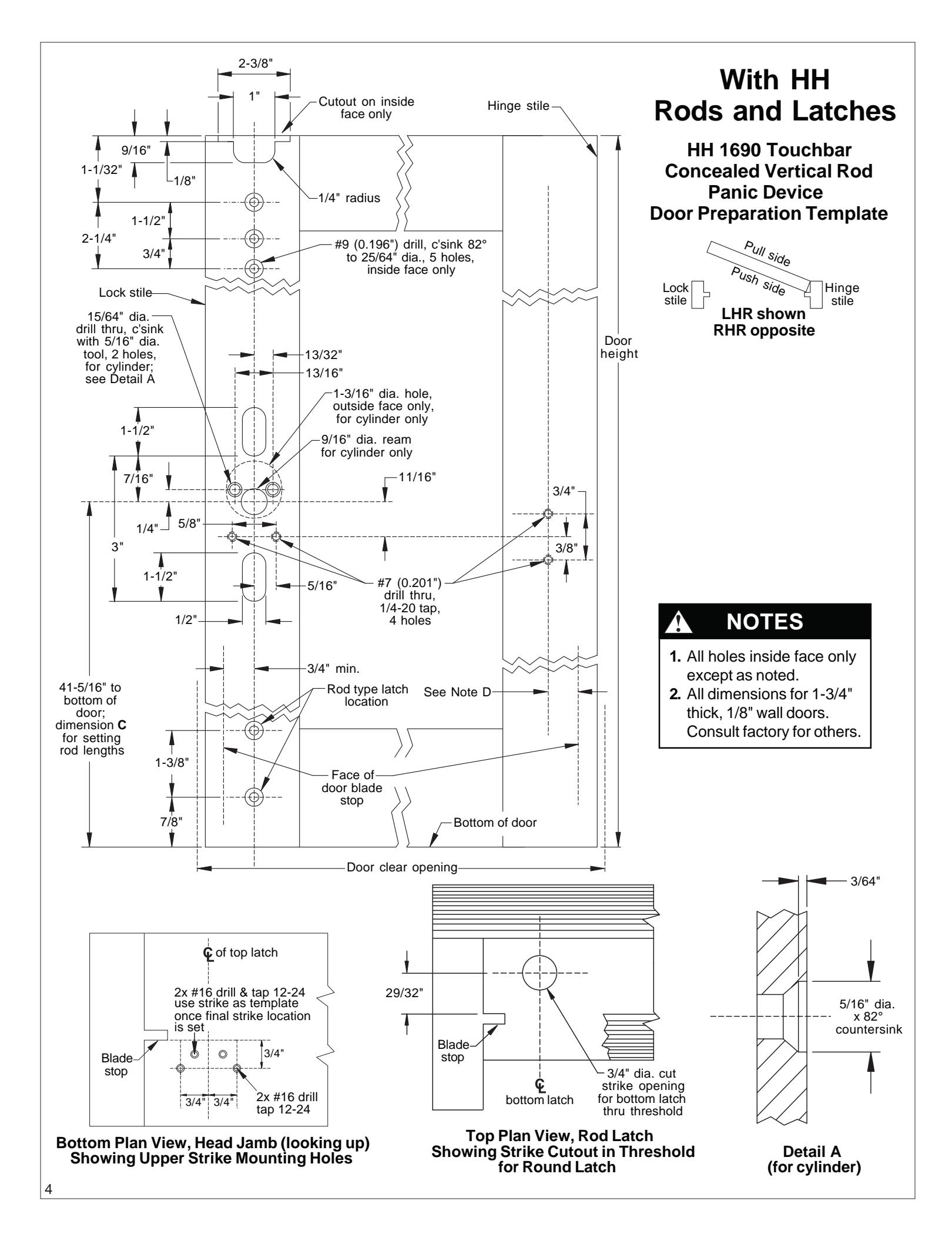
NOTE: The door prep for the HH 1690 Device is different than the standard 1690 Device. Please verify prep required (page 4) before prepping the door.
Index:
|
•
Parts List |
2 |
|---|---|
|
•
Touchbar Part Numbers |
3 |
|
•
Before Installation |
3 |
|
•
Template |
4 |
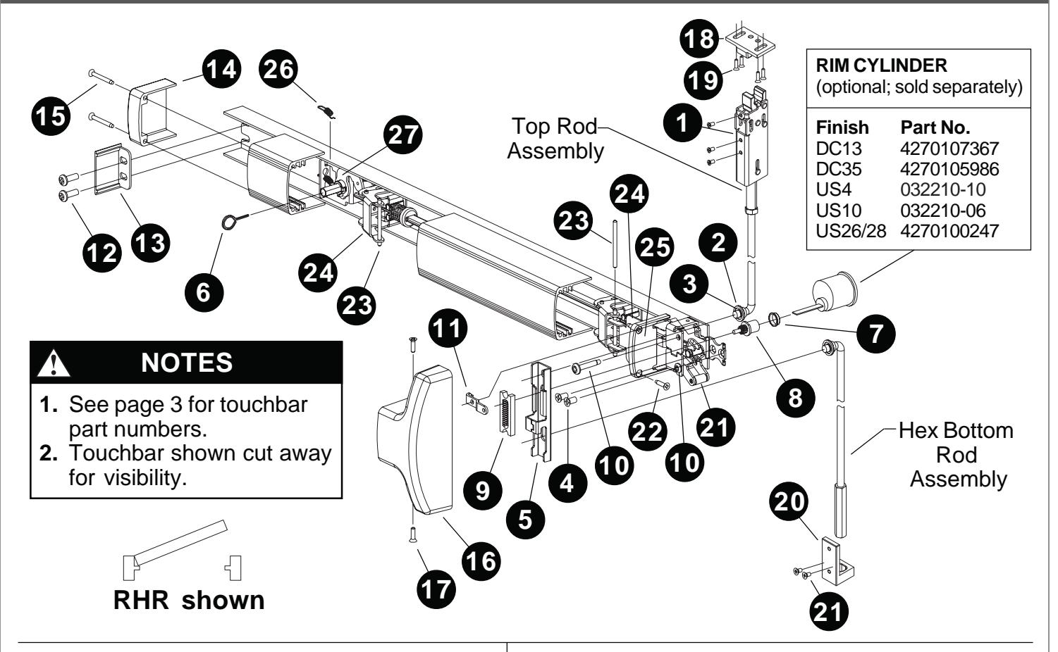
PARTS LIST
|
Package No. PKG.150 (US28 finish) or
Package No. PKG. 151 (DC13/DC35 finish) |
||||||
|---|---|---|---|---|---|---|
| Item | Quantity Description | Part No. | ||||
| 1 | 4 | #10-32 x 1/4" UFPHMS | ||||
| US28 finish | 963125-00 | |||||
| DC13/DC35 finish | 4270902255 | |||||
| 2 | 2 | Rod bearing bushing | BUSH.108 | |||
| 3 | 4 | Retaining ring | RRING.108 | |||
| 4 | 2 | 1/4-20 x 1/2" FPHMS | SCREW.1052 | |||
| 5 | 1 | Traveler lift bracket | BRKT.138 | |||
| Package No. CYLASY.1083 | ||||||
|---|---|---|---|---|---|---|
| 6 | 1 | 5/32" hex dogging key | 4270106944 | |||
| 5 | 1 | Traveler lift bracket | BRKT.138 | |||
| 4 | 2 | 1/4-20 x 1/2" FPHMS | SCREW.1052 | |||
| 3 | 4 | Retaining ring | RRING.108 | |||
|
Note:
Optional. Required with rim cylinder only. |
||||||
|---|---|---|---|---|---|---|
| Item | Quantity Description | Part No. | ||||
| 7 | 1 | Cylinder bushing | 4270100663 | |||
| 8 | 1 | Pinion cam | 4270100566 | |||
| 9 | 1 | Retractor | 4270903161 | |||
| 10 | 1 | Retainer screw | SCREW.1049 | |||
| 11 | 1 | Pinion support bracket | BRKT.133 | |||
| Note: For use with EO and DT devices only. | |||
|---|---|---|---|
| Item | Quantity Description | Part No. | |
| 10 | 1 | Retainer screw | SCREW.1049 |
| 11 | 1 | Pinion support bracket | BRKT.133 |
Package No. 4270902993
| Package No. ECAP.130 | ||||||
|---|---|---|---|---|---|---|
| Item | Quantity Description | Part No. | ||||
| 12 | 2 | 1/4-20 x 1/2" PPHMS | 4299100074 | |||
| 13 | 1 | Channel end cap | ECAP.127 | |||
| 14 | 1 | Hinge stile touchbar end cap | ECAP.128 | |||
| 15 | 2 | #8 x 1-1/4" FPHTF | 4299101314 | |||
| Package No. COVER.113 | ||||||||
|---|---|---|---|---|---|---|---|---|
| Item |
Quantity Description
Part No. |
|||||||
| 16 | 1 | Center case cover | COVER.112 | |||||
| 17 | 2 | #8 x 5/8" PPHTC Sems | 4299101318 | |||||
| Package No. 23955255-00 | ||||||
|---|---|---|---|---|---|---|
| Note: | Contains strike and four mounting screws. | |||||
| Item | Quantity | Description | Part No. | |||
| 18 | 1 | Strike | Strk. 134 | |||
| 19 | 4 | 12x24 1/2" UFPHMS | 964064-00 | |||
|
Package No. Guide 102 (US28 finish) or
Package No. Guide 103 (DC13/DC35 finish) |
|||||
|---|---|---|---|---|---|
| Item | Quantity Description | Part No. | |||
| 20 | 1 | HH hex rod guide | 4270109237 | ||
| 21 | 4 | 10-32 x 3/8" FPHMS | |||
| US28 finish | 4299100659 | ||||
DC13/DC35 finish 4299101011
| Item | Quantity Description | Part No. | |
|---|---|---|---|
| 22 | 1 | Lift arm | BRKTASSY.107 |
| 23 | 2 | #8 x 3/4" FPHTF | 4299101313 |
| 24 | 2 | Touchbar pin | PIN.125 |
| 25 | 2 | Touchbar anchor | BRKT.128 |
| 26 | 1 | Lock stile touchbar end cap ECAP.129 | |
| 27 | 1 | Dogging spring | 971493-89 |
| 28 | 1 | Dogging assembly | |
| DC13/DC35 finish | KIT.1022 | ||
| US28 finish | KIT.1021 |
2
PARTS LIST (CONTINUED)
STRAIGHT HEX BOTTOM ROD ASSEMBLY
Bent rod 37.812" long 4270101825 (can be shortened by 6") Jam nut 3/8"-24 4299100004 Straight Hex bolt 4270101830
TOUCHBAR PART NUMBERS
|
30" Nominal Device Length
(24.785" Extrusion Length) |
36" Nominal Device Length
(30.785" Extrusion Length) |
42" Nominal Device Length
(36.785" Extrusion Length) |
48" Nominal Device Length
(42.785" Extrusion Length) |
|||||
|---|---|---|---|---|---|---|---|---|
| Finish |
Without
Dogging Hole |
With
Dogging Hole |
Without
Dogging Hole |
With
Dogging Hole |
Without
Dogging Hole |
With
Dogging Hole |
Without
Dogging Hole |
With
Dogging Hole |
| DC13 | EXT.825 | EXT.828 | EXT.399 | EXT.609 | EXT.439 | EXT.736 | EXT.443 | EXT.739 |
| DC35 | EXT.826 | EXT.829 | EXT.400 | EXT.631 | EXT.441 | EXT.737 | EXT.444 | EXT.740 |
| US3 | EXT.2323 | EXT.2351 | EXT.2324 | EXT.2355 | EXT.2341 | EXT.2359 | EXT.2298 | EXT.2363 |
| US10 | EXT.2333 | EXT.2352 | EXT.2334 | EXT.2356 | EXT.2345 | EXT.2360 | EXT.2303 | EXT.2364 |
| US26 | EXT.2338 | EXT.2353 | EXT.2339 | EXT.2357 | EXT.2349 | EXT.2361 | EXT.2304 | EXT.2365 |
| US26D | EXT.2340 | EXT.2354 | EXT.2289 | EXT.2358 | EXT.2350 | EXT.2362 | EXT.2294 | EXT.2366 |
| US28 | EXT.830 | EXT.827 | EXT.398 | EXT.608 | EXT.438 | EXT.646 | EXT.442 | EXT.738 |
BEFORE INSTALLATION
- 1. Check "Parts List" (see page 2).
- 2. Prepare door using template on page 4.
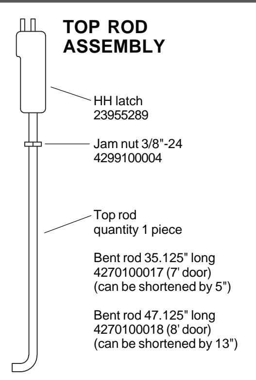
- 3. Set initial rod lengths (see ININST.1002 page 11). Rods are factory set for standard 7' door.
- 4. If door width is non-standard, cut device (see ININST.1002 page 12).
- 5. If necessary, re-hand device (see ININST.1002 page 11).
- 6. Continue with installation instructions in sheet ININST.1002.