Falcon Cylinder Dogging XX Device Installation Instructions 109652
Open the original PDF document
View PDFACTIVE CHASSIS -AND COVER 1 ARM AXLE CYLINDER DOGGING ASSY. NOTE: KEY WAY HORIZONTAL AFTER INSTALLATION FIG. 2
DOGGING CAM (SLOT PERPENDICULAR TO DOOR SURFACE)
LHR SHOWN RHR OPPOSITE
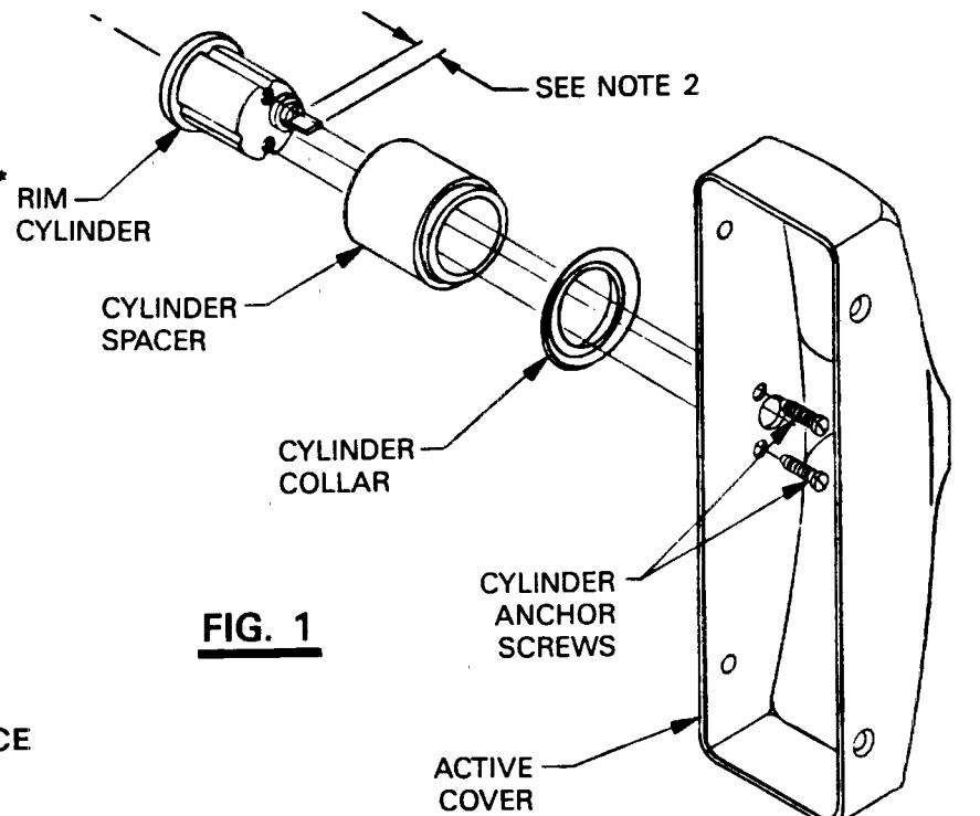
NOTE: RIM CYLINDER MUST HAVE VERTICAL TAILPIECE

© Allegion 2015 Printed in U.S.A. D-4085 Rev. 05/15-b
FALCON ®
INSTALLATION INSTRUCTIONS CYLINDER DOGGING XX DEVICE
DATE: 05-29-15
D-4085-B
INSTALLATION INSTRUCTIONS
XX -- Cyl. Dogging
- 1. If cylinder has been factory installed, proceed to Step 3. Assemble cylinder collar, cylinder spacer, and cylinder to active case cover using cylinder anchor screws provided with cylinder. (See Fig. 1)
- 2. Cut cylinder tailpiece to extend 3/6" inside cover.
-
3. For LHR Devices, install cover to chassis as follows. (See Fig. 2)
- A. Turn dogging cam in chassis to stop in undogged position. (CCW for RHR & CW for LHR). Slot will be perpindicular to door surface.
- B. Install cover/cylinder dogging assy, over arm and chassis per standard procedure.
- 4. Check for correct dogging function.
- 5. For LHR devices, reverse rotation and proceed as in Step 3.