Falcon B-Series Installation Instructions – English 106831
Open the original PDF document
View PDF

031728-000-70
B-Series
FALCON
Installation Instructions
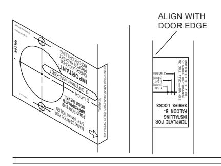
1. MARK DOOR
- A. Mark height line on edge of door approximately 38" from floor.
- B. Using the proper backset, mark 2-1/8" hole on both sides of the door.
- C. Mark 5/16" holes, two places on both sides of the door.
- D. Mark the center of the door edge for the
2. DOOR PREPARATION
5/16" HOLES
HOLE
A. Bore 2 1/8" hole thru and two 5/16" holes from both sides of door to prevent splintering door finish. B. Bore 1" hole
for latch on door edge. C. Using the latch faceplate as a guide, trace outline and mortise door edge so latch is flush with door
NOTE: Hollow metal doors must be properly reinforced for lock support (if support was not furnished contact door manufacturer.)
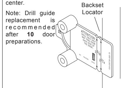
USING THE FALCON OP-TIONAL DRILL GUIDE
We recommend using a drill guide to ensure straight and level holes.
Install drill guide (030736- 000-70) into door. Make certain correct backset cators are even with door edge. Drill two (2) 5/16" (8mm) holes from both sides to center.
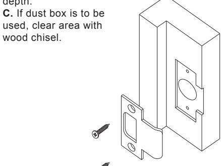
3. INSTALL STRIKE
A. Use strike locating tool or pointed object to locate position for hole in frame.
B. Bore 1" x 3/4" deep hole. Use strike as a template and mortise to the proper depth.
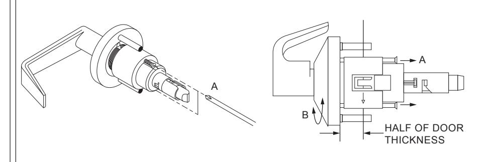
4. CHASSIS ADJUSTMENT
A. Remove chassis from door and loosen chassis screws until clear of mounting plate.
- B. Turn rose and mounting plate until chassis is centered with door.
- C. Align mounting plate with chassis screws and retighten chassis screws.
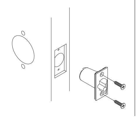
5. INSTALL LATCH ASSEMBLY
- A. Insert latch into door.
- B. Secure with two screws provided.
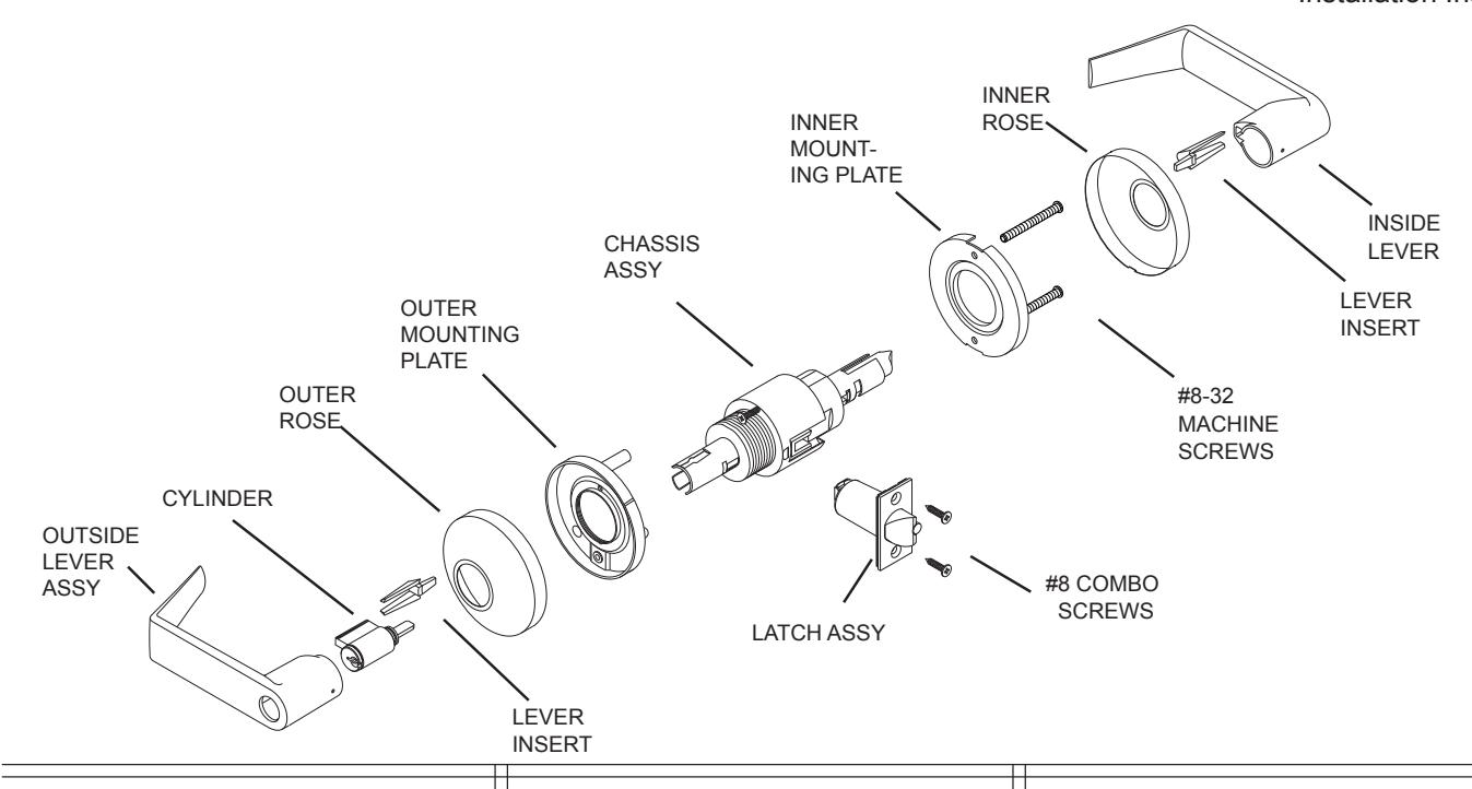
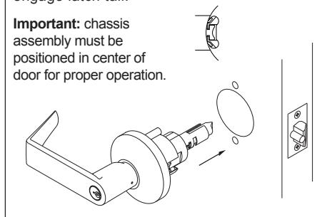
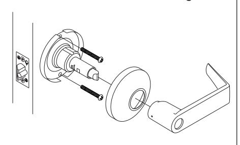
6. INSTALL OUTSIDE TRIM
- A. For ease of installation, lock should be in the unlocked position.
- B. Slide chassis assembly into door from outside making sure that lock housing engages latch prongs. Retractor must also engage latch tail.
7. REMOVING INSIDE ROSE
A. Pry rose from inner mounting plate using screwdriver inserted into opening. Be careful not to bend the rose.
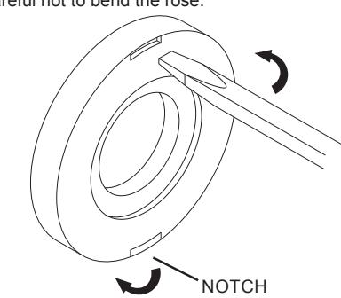
Note: Inside Rose has a notch to aid removal when installed. Please position this notch towards the bottom of the lock assembly.
8. INSTALL INSIDE TRIM
- A. Place mounting plate over chassis.
- B. Insert screws and tighten.
- C. Locate the notch on the edge of rose towards the bottom and push in until flush with face of door.
- D. Align lever with spindle and push until button engages with hole.
- E. Check function before closing door.
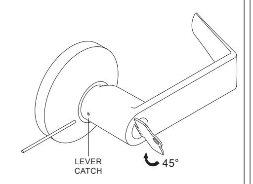
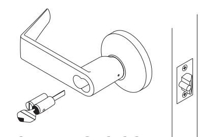
9. REMOVING LEVERS
- A. For outside levers only: Turn key or button 45° clockwise and hold.
- B. Depress lever catch and pull off lever and cvlinder.
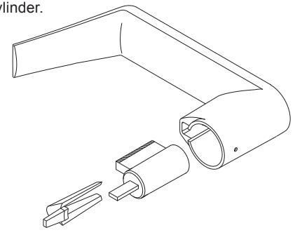
10. INSTALLING STANDARD CYLINDERS INTO LEVERS
- A. Insert cylinder into lever.
- B. Insert key into cylinder to hold and align cylinde
- C. Insert cylinder retainer into lever to secure cylinder.
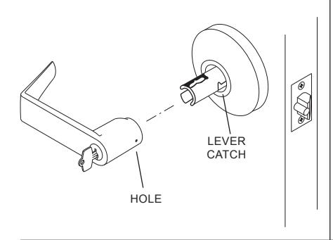
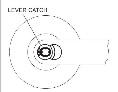
11. INSTALLING STANDARD CYLINDERS & LEVERS
- A. Align hole in lever with lever catch on spindle assembly and slide lever up to lever catch.
- B. For outside levers only: Turn key or button 45° clockwise and hold.
- C. Push lever in to engage lever catch.
- D. Check function before closing door.
REMOVING IC CORE
- . Unlock lockset
- B. Turn control key 15° clockwise or until key
- C. Pull key to remove IC core.
13. INSTALLING IC CORE
- A. With control key in core rotate key 15° clockwise and insert fully into
- B. Turn the key counter-clockwise and remove key
- C. Check function before closing door
14. REMOVING IC LEVERS
A. With IC core removed, using a screwdriver, depress lever catch and pull lever to remove
15. INSTALLING IC LEVERS
A. Push lever in until lever catch engages with lever
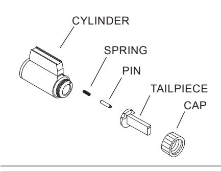
16. TAILPIECE INSTALLATION
- A. Insert spring and pin into cylinder.
- B. Place tailpiece into cap. C. Thread cap onto the cylinder.
NOTE: The cap must be properly adjusted. If too loose, excessive plug end play will prevent the key from being withdrawn. If too tight, the plug will drag and be difficult to rotate with the key.
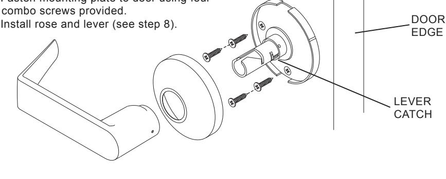
17. DUMMY INSTALLATION
A. Remove lever and rose (see step 9). B. Position mounting plate as required with lever catch towards door edge.
C. Fasten mounting plate to door using four #8 combo screws provided.
D. Install rose and lever (see step 8).
18. CYLINDER TIMING
FOR B371 .
- A. Install lock on door as shown in steps 1 thru
- B. Using a 1/4" diameter philips screwdriver, turn key spindle until stop and lever is locked.
- C. Turn back the key spindle 1/2 turn. D. If IC go to E. Remove standard cylinder lever
- E. Insert cylinder into lever as shown in step 10.
- F. Insert lever and cylinder onto spindle as shown in step 11.
- G. Repeat A. thru F. for opposite side.
-
H. Check operation:
-
Outside -turn key CCW 270° to unlock.
- turn key CW 180° to lock. Inside turn key CW 270° to unlock. turn key CCW 180° to lock.
-
Outside -turn key CCW 270° to unlock.
FOR B391 & B561 :
- A. Install lock on door as shown in steps 1 thru
- B. Using a 1/4" diameter philips screwdriver, turn key spindle until stop and lever is unlocked.
- C. If IC go to G. Remove standard cylinder
- D. Insert cylinder into lever as shown in step 10.
- E. Slide lever and cylinder onto the spindle and push the cylinder in to engage the key spindle. F. Insert key into cylinder and turn CW 45° as
- shown in step 9. Go to step H.
- G. For IC: Insert cylinder into lever as shown in step 12.
- H. Check operation:
Outside -turn key CW 360° to unlock. turn key CC W 360° to lock.
Customer Service

1-877-671-7011
www.allegion.com
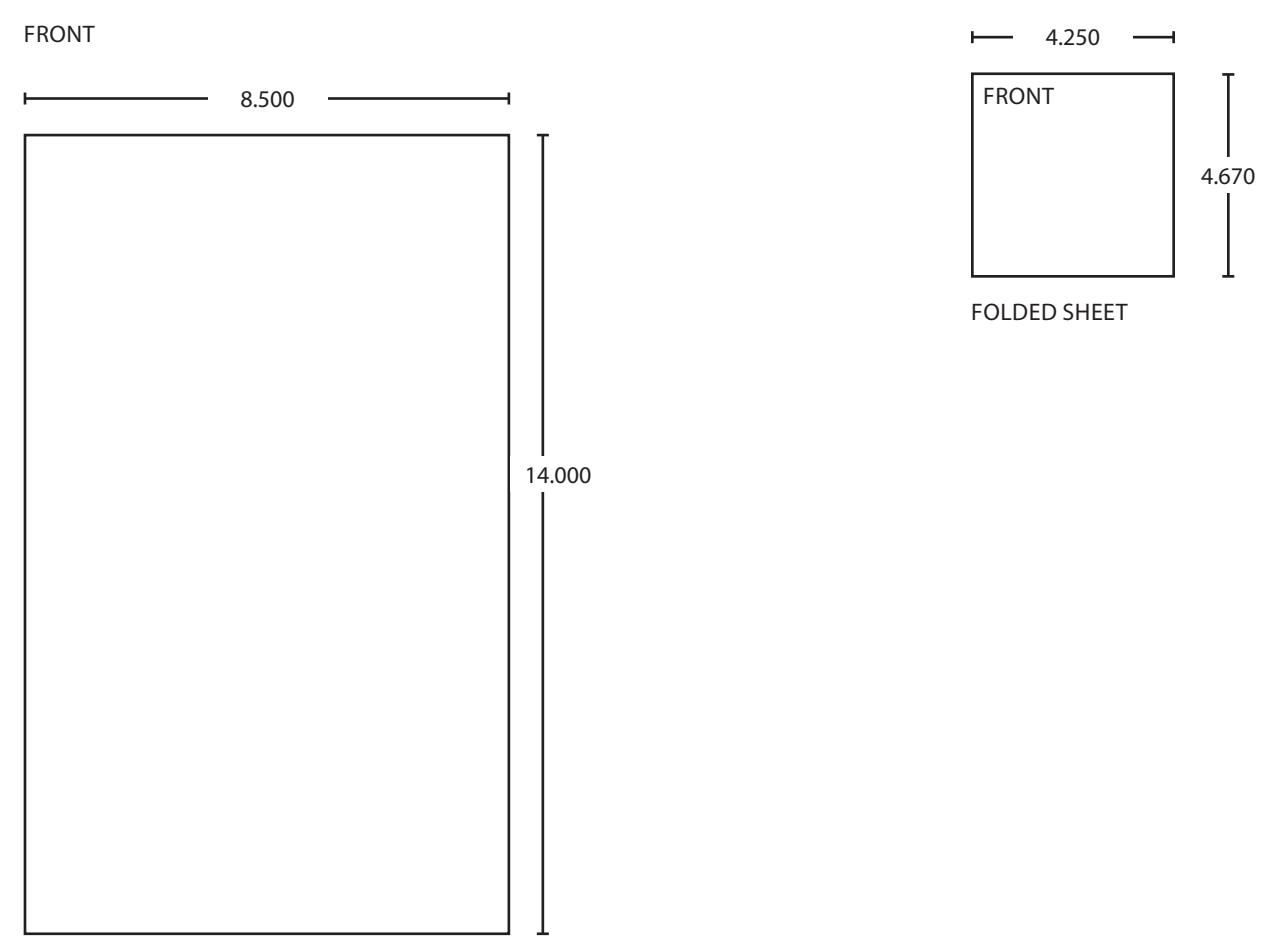
BEGINNING SHEET
| Additional Notes: |
|---|
| 1. None |
| Revision History | Revision Description: | |||||||||
|---|---|---|---|---|---|---|---|---|---|---|
| А | В | С | D | Е | F | D > Revised artwork | ||||
| 5598 | 0790 | 6683 | ||||||||
| Material White Paper | Edited By | Approved By | EC Number | Release Date | ||||||
| D. Spence | M. Sasso | 042447 | 01-01-14 | |||||||
| Notes | Title | |||||||||
|
Instruction Sheet, B-Series | |||||||||
| 3. tolerance ± .13 | Creation Date | Number | Revision | |||||||
|
11-07-13 031728-00 | )-70 | D | |||||||
| J. diawii | 3. drawings not to scale |
Created By
D. Spence |
Activity
3899 Hancock Expwy |
|||||||
| Software: InDesign CS6 | Security, CO 80911 | © Allegion 2014 | ||||||||