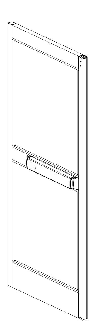
Falcon 2390 Touchbar Concealed Vertical Rod Panic Device Installation Instructions 108178
Open the original PDF document
View PDF

2390 Touchbar
ININST.1039
Concealed Vertical Rod Panic Device
Installation Instructions
| Index |
|---|
|
•
Parts List 2 • Before Installation 5 • Installation 5 • RX Device Wiring 12 • EL Device Wiring 13 • Cylinder Installation 14 • Touchbar Dogging 17 • Setting Rod Lengths 18 • Re-handing Device 19 • Template 20 |

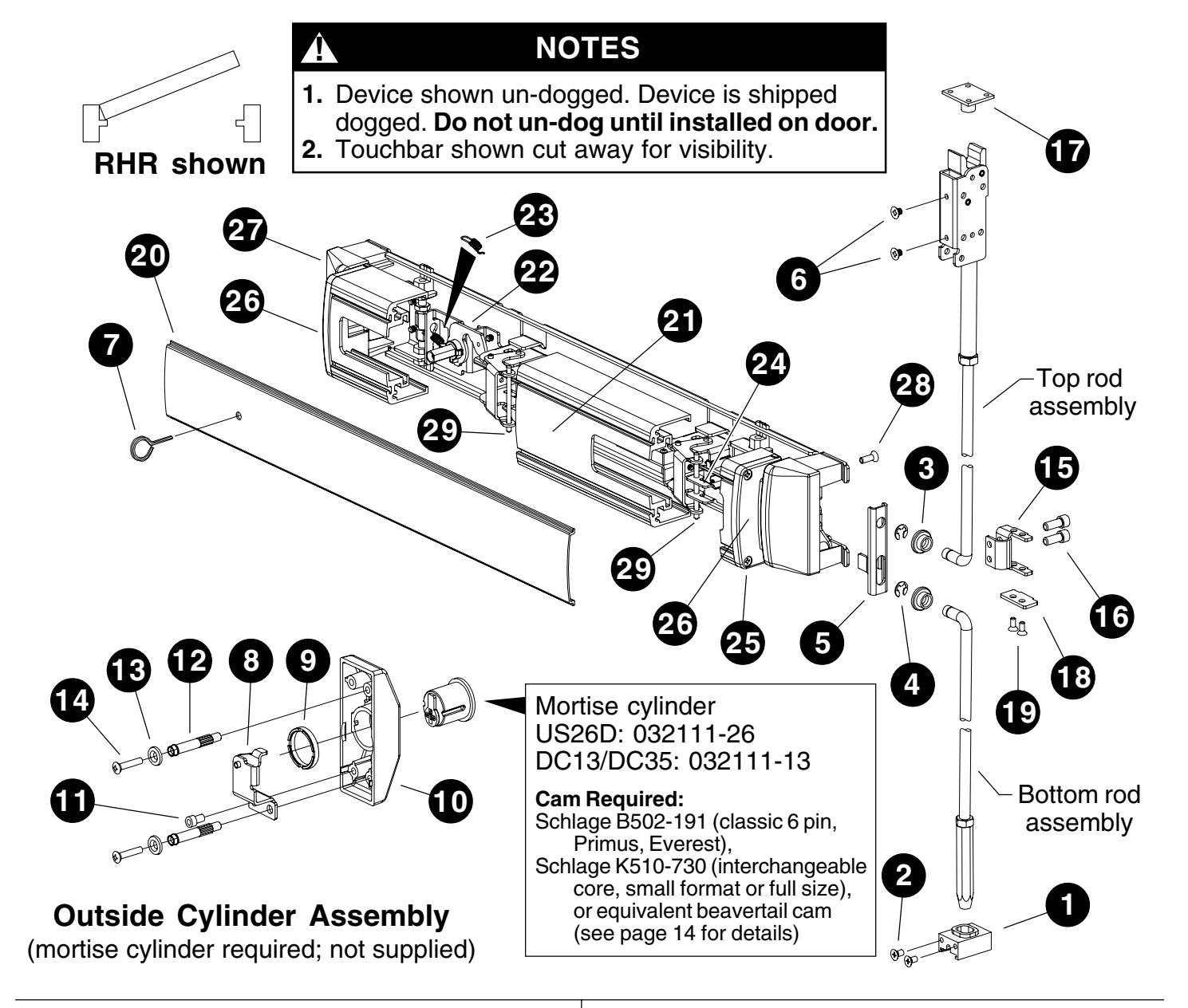
PARTS LIST
|
Package
No. 4270107176 (US28 finish) or Package No. 4270107178 (DC13/DC35 finish) |
||||||
|---|---|---|---|---|---|---|
| Item | Quantity | Description |
Part
No. |
|||
| 1 | 1 |
Hex
rod guide |
4270101829 | |||
| 2 | 2 |
#10-24
x 3/8" UFPHTC Typ |
F
Stl |
|||
|
US28
finish |
4299100746 | |||||
|
DC13/DC35
finish |
4299101027 | |||||
|
Package
No. PKG. 134 (US28 finish) or Package PKG. finish) |
||||||
| No. |
135
(DC13/DC35 |
|||||
| Item | Quantity | Description |
Part
No. |
|||
| 3 | 2 |
Rod
bearing bushing |
BUSH.108 | |||
| 4 | 2 |
Reinforced
retaining ring |
RRING.108 | |||
| 5 | 1 |
2390
lift bracket |
BRKT.143 | |||
| 6 | 2 |
#10-32
x 1/4" UFPHMS US28 finish |
963125-00 | |||
7 1 5/32" hex dogging key 4270106944
|
Package
No.CYLASY.1046 (P28 finish) or Package No. CYLASY.1053 (P35 finish) |
|||||
|---|---|---|---|---|---|
| Item | Quantity | Description |
Part
No. |
||
| 8 | 1 |
2390
NL/HB bracket assy. |
BRKTASY.118 | ||
| 9 | 1 |
Mortise
locking collar |
971851-00 | ||
| 10 | 1 |
2390
cylinder housing |
|||
|
P13
finish |
HOUSING.124 | ||||
|
P28
finish |
HOUSING.123 | ||||
|
P35
finish |
HOUSING.125 | ||||
| 11 | 1 |
1/4-20
x 3/8" SHCS |
820975-00 | ||
| 12 | 2 |
Mounting
stud |
971585-89 | ||
| 13 | 2 |
#10
countersink washer |
|||
|
DC13/DC35
finish |
WASHER.117 | ||||
|
US32D
finish |
964016-00 | ||||
| 14 | 2 |
#10-24
x 1" OPHMS |
|||
|
DC13/DC35
finish |
SCREW.1014 | ||||
|
US32D
finish |
963120-00 | ||||
| 15 | 1 |
2390
cylinder lift bracket |
BRKT.152 | ||
| 16 | 2 |
1/4-28
x 3/4" SHCS |
SCREW.1034 | ||
Package No. CYLASY.1047 (P13 finish) or
|
Package
No. PB48 |
Item | Quantity | Description |
Part
No. |
|||
|---|---|---|---|---|---|---|---|
| Note: | Contains |
PB48
strike, three shims, four |
mounting
screws. |
20 | 1 |
Cover
plate |
See
table |
| Item | Quantity | Description |
Part
No. |
21 | 1 | Touchbar |
See
table |
| 17 | 1 | Strike | 22 | 1 |
Dogging
assembly |
||
|
P13
finish |
4270108354 |
DC13/DC35
finish |
KIT.1022 | ||||
|
P35
finish |
4270108355 |
US28
finish |
KIT.1021 | ||||
| 23 | 1 |
Dogging
spring |
971493-89 | ||||
|
US28
finish |
4270108353 | 24 | 1 |
2390
touchbar anchor bracket |
BRKT.137 | ||
| 25 | 4 |
#8
x 3/4" FPHTF |
4270109556 | ||||
| Package |
No. BRKTASY.155
(for 2" thick |
doors
only) |
26 | 2 |
2390
mounting end cap P35 |
ECAP.143 | |
| Item | Quantity | Description |
Part
No. |
27 | 2 |
2390
fixed cover P35 |
COVER.127 |
| 18 | 1 |
2390
lift bracket 2" door |
BRKT.154 | 28 | 4 |
#12-14
x 1/2" UFPH Typ 23 |
SCREW.1007 |
| 19 | 2 |
#8-18
x 5/16" UFPHSMS |
964327-89 | 29 | 2 |
Touchbar
pin |
PIN.125 |
Cover Plate Part Numbers (Item 20 in "Parts List")
|
21"
Touchbar |
Length |
24"
Touchbar |
Length | |
|---|---|---|---|---|
| Finish |
Without
Dogging Hole |
With
Dogging Hole |
Without
Dogging Hole |
With
Dogging Hole |
| Champagne | EXT.2462 | EXT.3011 | EXT.2466 | EXT.3015 |
| DC13 | EXT.2460 | EXT.3009 | EXT.2464 | EXT.3013 |
| DC35 | EXT.2461 | EXT.3010 | EXT.2465 | EXT.3014 |
| US28 | EXT.2459 | EXT.3008 | EXT.2463 | EXT.3012 |
Touchbar Part Numbers (Item 21 in "Parts List")
| Finish |
21"
Touchbar Length |
24"
Touchbar Length |
|---|---|---|
| Champagne | EXT.3003 | EXT.3007 |
| DC13 | EXT.3001 | EXT.3005 |
| DC35 | EXT.3002 | EXT.3006 |
| US28 | EXT.3000 | EXT.3004 |
2390 Channel Package No. 4270108768 (used for mounting muntin to vertical door stiles)
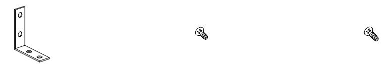
2390 angle bracket Part No. 4204100819 Quantity: 4 pieces
#8-32 x 3/8" FPHTC Part No. 4299100726 Quantity: 8 pieces
#8-32 x 1/2" FPHTC Part No. 4299100741 Quantity: 8 pieces
PARTS LIST (continued)
Muntin Filler Part Numbers
| Finish |
Muntin
Filler Part Number |
|---|---|
| DC13 | 4270107327 |
| DC35 | 4270107328 |
| US28 | 4270107325 |
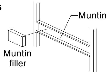
Muntin Part Numbers
| Finish |
Muntin
Part Number |
|---|---|
| DC13 | 4270102811 |
| DC35 | 4270102812 |
| US28 | 4270102809 |
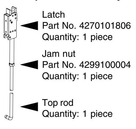
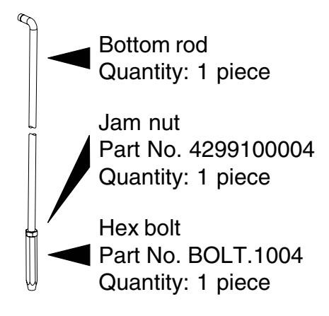
Top Rod Assembly Bottom Rod Assembly
Standard 7' Door Top Rod Assemblies (dimensions in inches)
| Description | Part No. | Muntin Center Line Door Height |
By
Cutting Top Rod, Assembly Can Be Shortened Up To |
|
|---|---|---|---|---|
|
2390
Top Rod RHR AL = 40.176 |
RODASY.10001 | 42.5 | 83.188 | 4" |
|
2390
Top Rod RHR AL = 41.426 |
RODASY.10002 | 41.25 | 83.188 | 6" |
|
2390
Top Rod RHR AL = 44.801 |
RODASY.10003 | 37.875 | 83.188 | 9" |
|
2390
Top Rod RHR AL = 42.676 |
RODASY.10004 | 40 | 83.188 | 5" |
|
2390
Top Rod RHR AL = 41.489 |
RODASY.10005 | 41.25 | 83.25 | 6" |
|
2390
Top Rod LHR AL = 40.176 |
RODASY.10006 | 42.5 | 83.188 | 4" |
|
2390
Top Rod LHR AL = 41.426 |
RODASY.10007 | 41.25 | 83.188 | 6" |
|
2390
Top Rod LHR AL = 44.801 |
RODASY.10008 | 37.875 | 83.188 | 9" |
|
2390
Top Rod LHR AL = 42.676 |
RODASY.10009 | 40 | 83.188 | 5" |
|
2390
Top Rod LHR AL = 41.489 |
RODASY.10010 | 41.25 | 83.25 | 6" |
Standard 7' Door Bottom Rod Assemblies (dimensions in inches)
| Description | Part No. | Muntin Center Line Door Height | |
|---|---|---|---|
|
2390
Btm Rod = 41.877 |
RODASY.10011 | 42.5 | 83.188 |
|
2390
Btm Rod = 40.627 |
RODASY.10012 | 41.25 | 83.188 |
|
2390
Btm Rod = 37.252 |
RODASY.10013 | 37.875 | 83.188 |
|
2390
Btm Rod = 39.377 |
RODASY.10014 | 40 | 83.188 |
PARTS LIST (continued)
2390 Extension Rod Kit (Part No. EXTROD.1001)
| Description |
Part
No. |
Quantity |
|---|---|---|
|
3/8-24
jam nut Upper extension rod 7.5" Lower extension rod 6.5" Extension tube 70" 1/8" x 5/8" roll pin |
4299100004
ROD.1049 ROD.1048 TUBE.300 4299100060 |
1
1 1 1 2 |
BEFORE INSTALLATION
- 1. Check "Parts List" (page 2 and page 3).
- 2. Prepare door using template on page 18.
- 3. Set initial rod lengths (see page 16). Rods lengths are factory set as specified on customer order.
- 4. If necessary, re-hand device (see page 17) and top rod (see Figure 1-1, page 4).
INSTALLATION
1 Install rod assemblies.
1.1. If using outside cylinder, install cylinder lift bracket on top rod (Figure 1-1). Do not tighten completely (final position will be determined in door). For 2" thick doors only , also install lift bracket 2" thick door and screws (#8-18 x 5/16" UFPHSMS) from package No. BRKTASY.155.
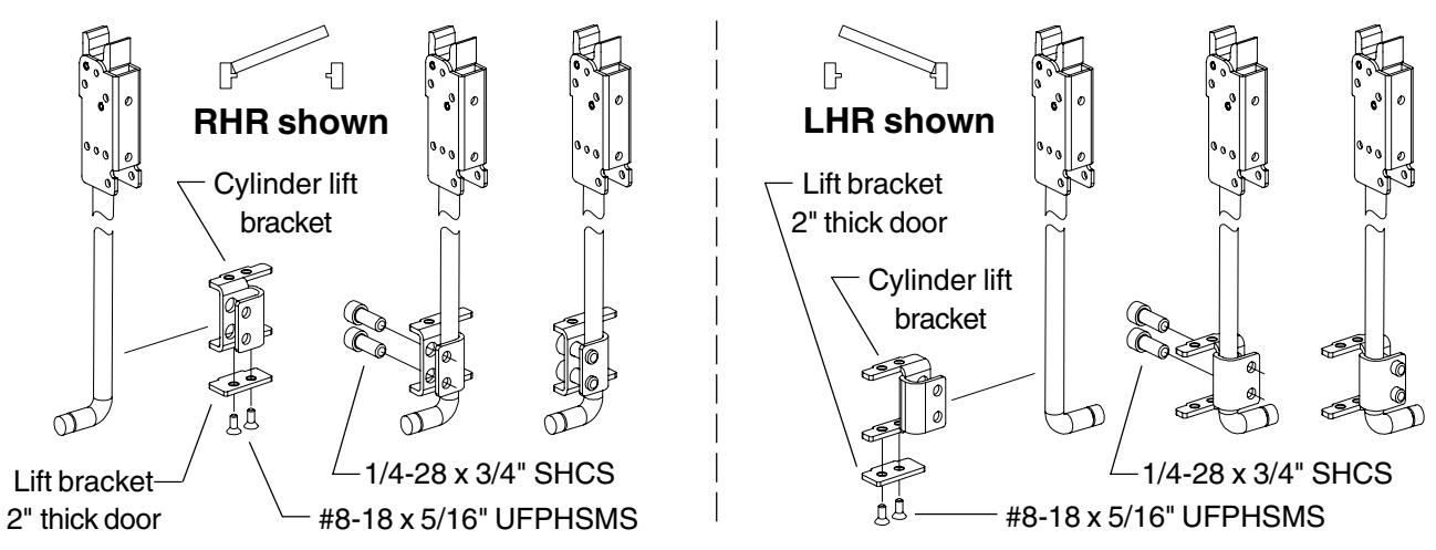
Figure 1-1
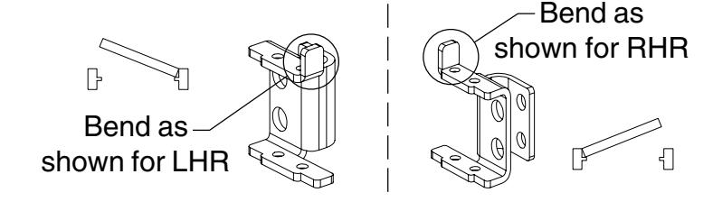
! NOTE
If using on narrow architectural stile with adjustable astragal, bend one ear only of cylinder lift bracket as shown at right before installing.
1 Install rod assemblies (continued).
1.2. Fit top rod assembly into door.
! NOTE To simplify fitting rod and lift bracket through stile, remove lift bracket and reinstall after top rod is in door (prior to Step 11.5).
- 1.3. Secure top rod assembly with two #10-32 x 1/4" UFPH machine screws.
- 1.4. Install top rod bearing bushing and retaining ring. Be sure retaining ring seats securely in groove on rod.
Figure 1-2
2.1. Measure muntin length (Figure 2-1) and stile offset (Figure 2-2).
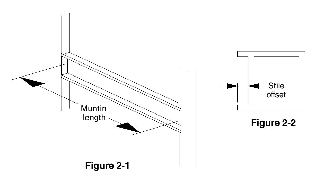
2.2. If measured muntin length (width between stiles) is less than the minimum listed in Minimum Muntin Length table, the device is too long for the application.
Minimum Muntin Length
|
Stile
Offset |
Minimum Muntin Length
(width between stiles) |
|||
|---|---|---|---|---|
| 0.115" | 27.505" | |||
| 0.125" | 27.495" | |||
| 0.142" | 27.478" | |||
| 0.156" | 27.464" | |||
| 0.187" | 27.433" | |||
|
Long
Device (24" touchbar) |
Short |
Device
(21" touchbar) |
||
|---|---|---|---|---|
|
Stile
Minimum Muntin Length Offset (width between stiles) |
Stile
Offset |
Minimum Muntin Length
(width between stiles) |
||
| 0.115" | 27.505" | 0.115" | 24.505" | |
| 0.125" | 27.495" | 0.125" | 24.495" | |
| 0.142" | 27.478" | 0.142" | 24.478" | |
| 0.156" | 27.464" | 0.156" | 24.464" | |
| 0.187" | 27.433" | 0.187" | 24.433" | |
2.3. Calculate muntin filler length (Figure 2-3) using formula from Muntin Filler Length table and cut muntin filler to length.
Muntin Filler Length
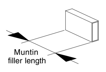
Figure 2-3
|
Long
Device (24" touchbar) |
|||
|---|---|---|---|
|
Stile
Offset |
Muntin Filler Length | ||
|
0.115"
0.125" 0.142" 0.156" 0.187" |
= muntin length–
27.505" = muntin length– 27.495" = muntin length– 27.478" = muntin length– 27.464" = muntin length– 27.433" |
||
|
Short
Device (21" touchbar) |
||||
|---|---|---|---|---|
|
Stile
Offset |
Muntin Filler Length | |||
| 0.115" |
= muntin length–
24.505" |
|||
| 0.125" |
= muntin length–
24.495" |
|||
| 0.142" |
= muntin length–
24.478" |
|||
| 0.156" |
= muntin length–
24.464" |
|||
| 0.187" |
= muntin length–
24.433" |
|||
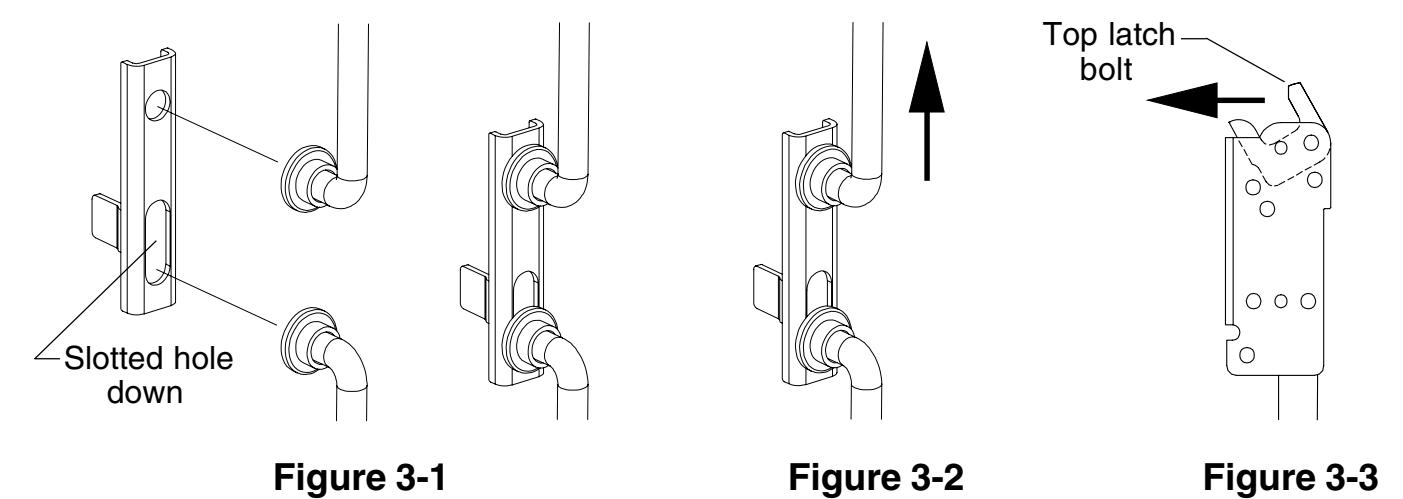
3 Install traveler.
- 3.1. Position traveler as shown (Figure 3-1) and place over rod ends.
- 3.2. Push top rod up until rods are held retracted, traveler is held up (Figure 3-2), and top latch bolt is locked forward (Figure 3-3).
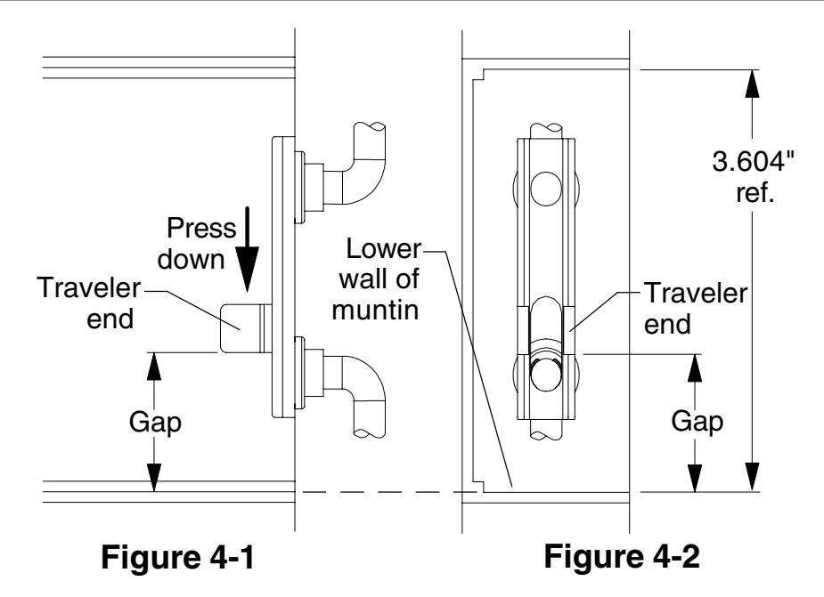
4 Adjust top rod.
- 4.1. With top rod retracted (see Step 3), press down on traveler end as shown (Figure 4-1). Make sure traveler is held over rod ends and against rod bushings.
- 4.2. Measure the gap between the bottom of the traveler end and the lower wall of the muntin (Figure 4-1 and Figure 4-2). Adjust top rod per directions in table below.
| Gap | Directions | |
|---|---|---|
| 1.193" |
Rod
adjustment is correct. Go to Step 5. |
|
| 1.151" |
Shorten
rod one (1) turn and repeat Step 4. |
|
| 1.110" |
Shorten
rod two (2) turns and repeat Step 4. |
|
| 1.068" |
Shorten
rod three (3) turns and repeat Step 4. |
|
| 1.235" |
Lengthen
rod one (1) turn and repeat Step 4. |
|
| 1.276" |
Lengthen
rod two (2) turns and repeat Step 4. |
|
| 1.318" |
Lengthen
rod three (3) turns and repeat Step 4. |
|
5 Prepare hole for EL/RX device. (If device is not EL/RX, go to Step 6.)
5.1. Drill 3/8" diameter hole for EL/RX wiring throughinside face of door, hinge side.
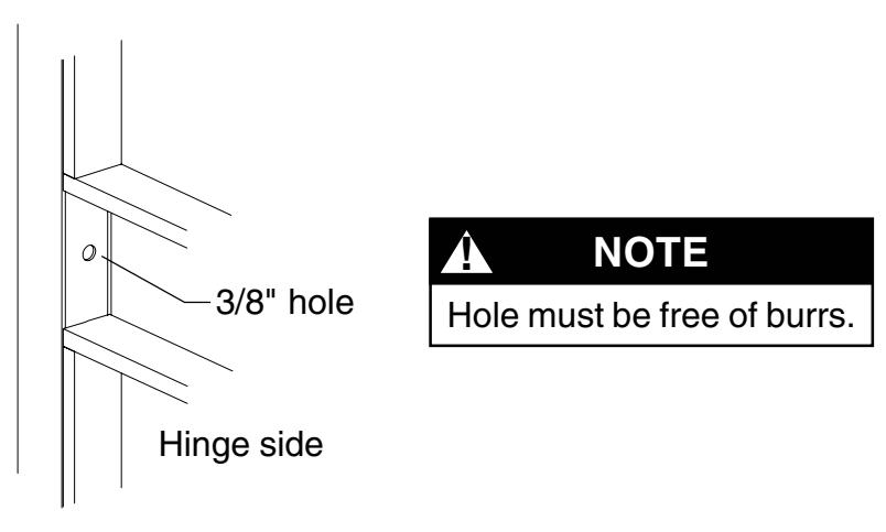
Figure 5-1
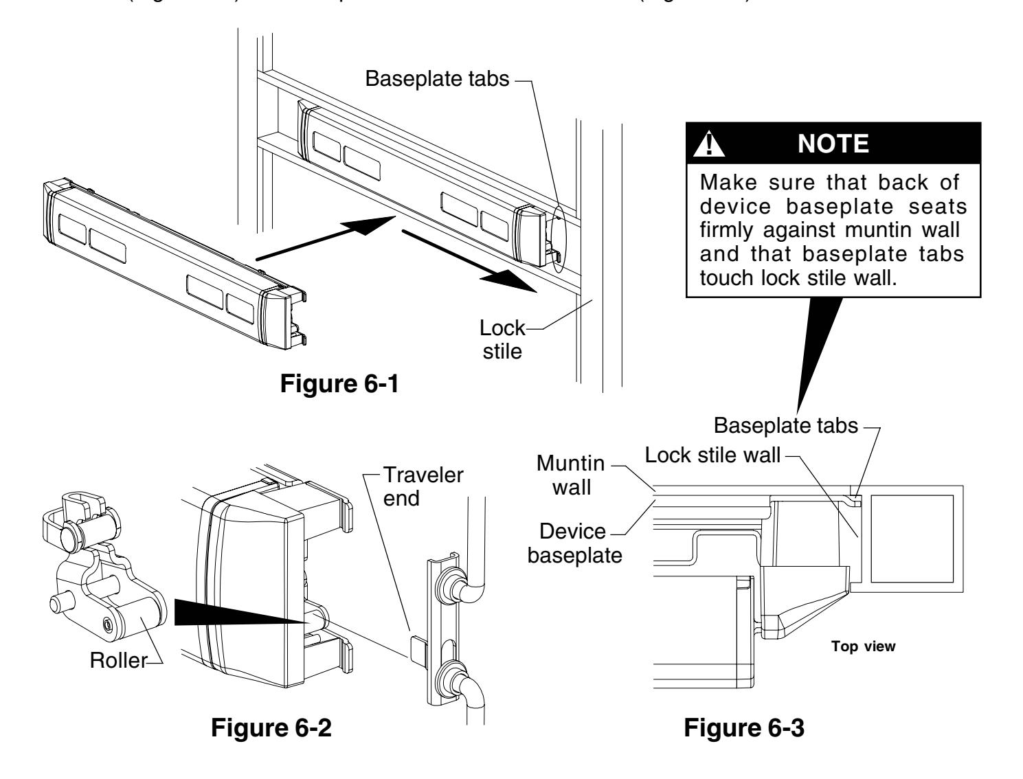
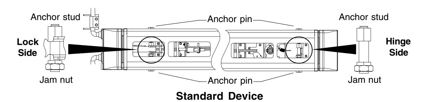
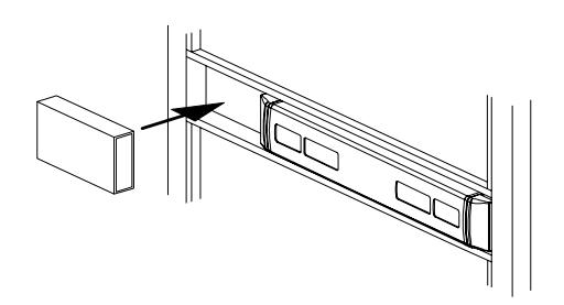
6 Install device.
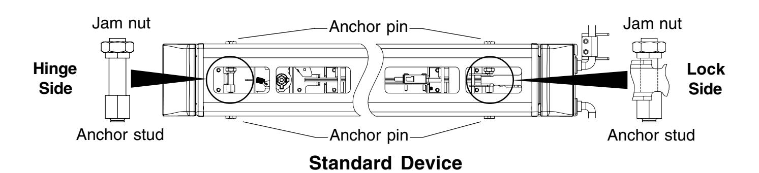
6.1. Place dogged device in door and slide toward lock stile (Figure 6-1) so roller fits under traveler end (Figure 6-2) and baseplate tabs touch lock stile wall (Figure 6-3).
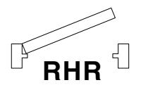
7A Secure RHR device. (See next page for LHR device.)
7A.1. With device seated against bottom of muntin, use a 3/8" open end wrench to tighten two gold color anchor studs to extend anchor pins. Tighten only until resistance is felt.
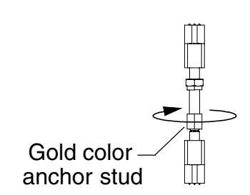
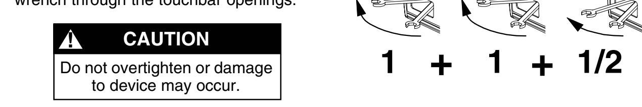
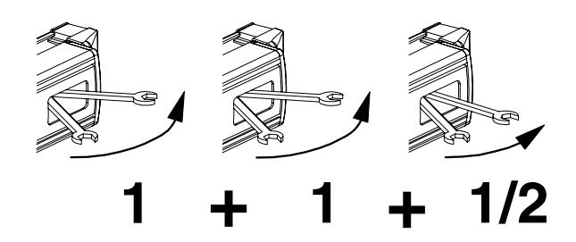
7A.2. After resistance is felt, tighten two gold color anchor studs 2-1/2 more movements of the wrench through the touchbar openings.
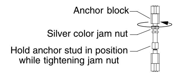
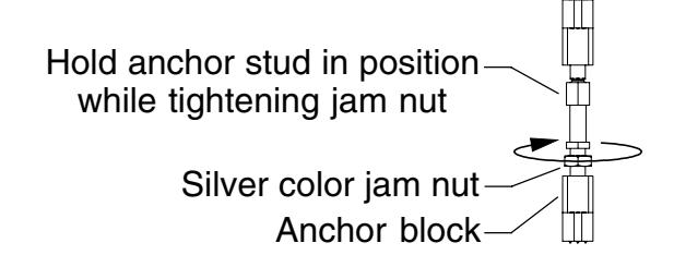
7A.3. Using a 7/16" open end wrench, tighten two silver jam nuts against anchor blocks. Use a 3/8" open end wrench to hold anchor studs in position while tightening jam nuts.
7B Secure LHR device. (See previous page for RHR device.)
7B.1. With device seated against bottom of muntin, use a 3/8" open end wrench to tighten two gold color anchor studs to extend anchor pins. Tighten only until resistance is felt.
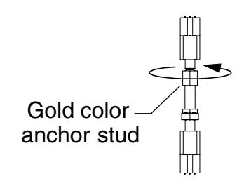
7B.2. After resistance is felt, tighten two gold color anchor studs 2-1/2 more movements of the wrench through the touchbar openings.
! CAUTION
Do not overtighten or damage to device may occur.
7B.3. Using a 7/16" open end wrench, tighten two silver jam nuts against anchor blocks. Use a 3/8" open end wrench to hold anchor studs in position while tightening jam nuts.
RX Device Wiring
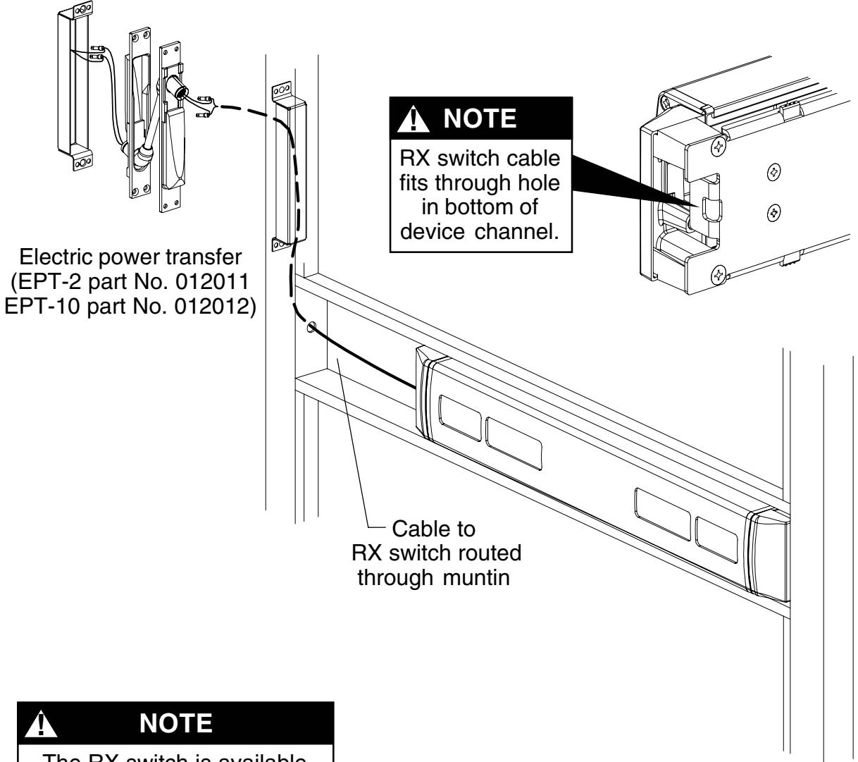
The RX switch is available only as a factory installed item. Part No. WIRE.1001 can be used only to replace the factory installed RX switch.
RX switch (part No. WIRE.1001)
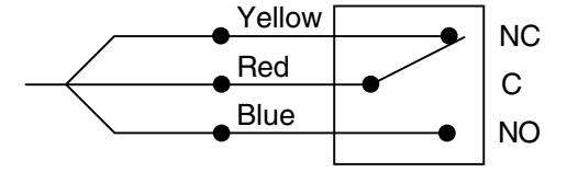
Switch shown not activated (touchbar not depressed)
- The RX switch is activated when the touchbar is depressed.
- Use the Von Duprin EPT-10 power transfer (for three wires), EPT-2 power transfer (for two wires), electric hinge, electric pivot, or door loop to transfer the wiring from the door to the frame.
- Connect the power transfer wires and switch assembly wires with crimp connectors. Unused wires should be insulated separately.
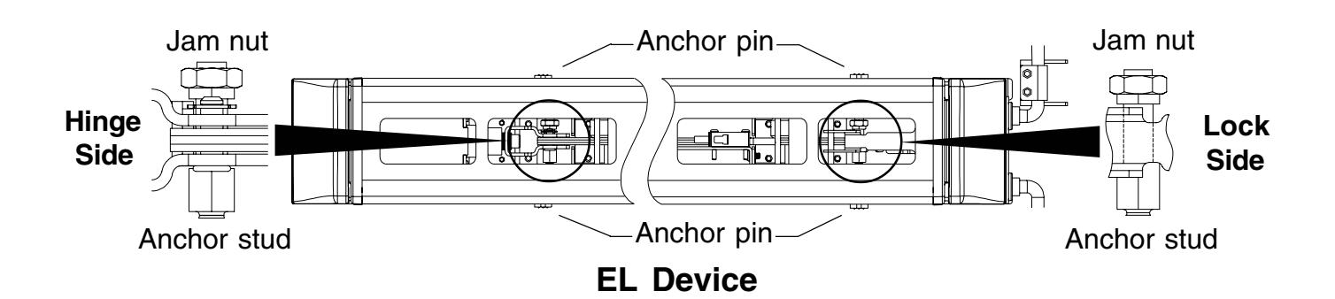
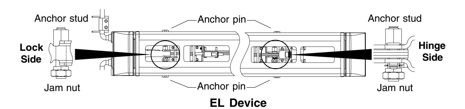
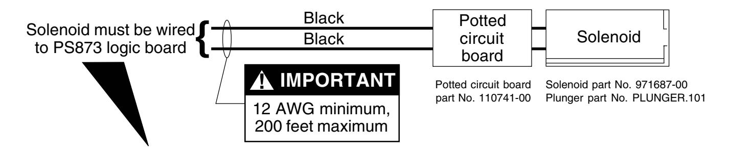
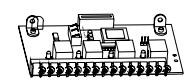
EL Device Wiring
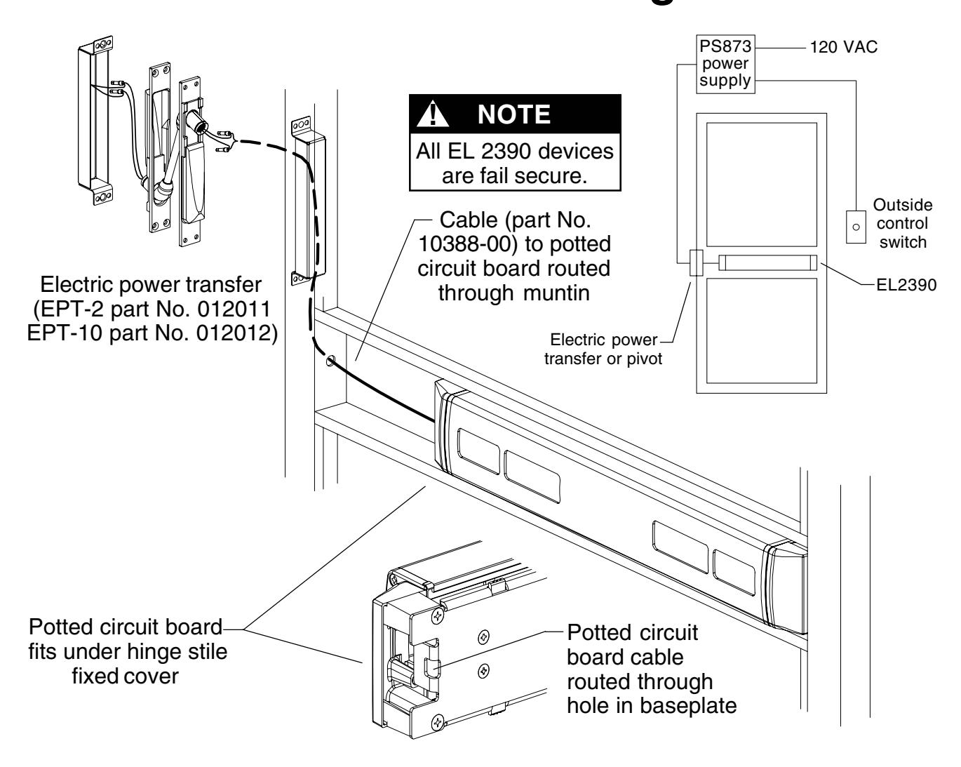
NOTE
The potted circuit board is a protection circuit. It disconnects power from the solenoid if the plunger does not seat within a specified time. To reset the protection circuitry, remove power from the solenoid and reapply.
Electrical Specifications
Voltage: 24 VDC
Current: 16 A inrush (0.3 sec.)
0.25 A holding
If 871-2 logic board, refer to Von Duprin instructions 941352.
Any reference to Von Duprin EL devices also applies to EL2390.
If other 873 logic board, refer to Von Duprin instructions 941353. Any reference to Von Duprin EL
devices also applies to EL2390.
10 Adjust bottom rod.
- 10.1. Undog the device(see page 17)and release the top latch bolt so it faces up (Figure 10-1).
- 10.2. Pull bottom rod out as far as it will extend from door. Do not depress touchbar during this step.
-
10.3.
Measure the bottom bolt extension from the door (Figure 10-2):
- • If extension equals 7/16" rod is set correctly. Go to Step 11.
- • If extension is more than 7/16" shorten rod per Table 10-1.
- • If extension is less than 7/16" lengthen rod per Table 10-2.
Table 10-2 Extension Less than 7/16"
|
Extension Lengthen
Rod |
||
|---|---|---|
| 13/32" | 1 turn | |
| 3/8" |
2
turns |
|
| 11/32" |
2
turns |
|
| 5/16" |
3
turns |
|
| 9/32" |
4
turns |
|
| 1/4" |
5
turns |
|
| 7/32" |
5
turns |
|
| 3/16" |
6
turns |
|
| 5/32" |
7
turns |
|
| 1/8" |
8
turns |
|
| 3/32" |
8
turns |
|
| 1/16" |
9
turns |
|
| 1/32" | 10 turns | |
| 0" |
11
turns |
|
To change rod length, remove two guide mounting screws,remove guide,rotate bolt, re-install guide. ! NOTE
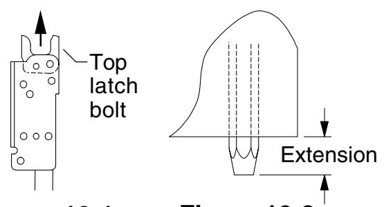
Figure 10-1 Figure 10-2
Table 10-1 Extension More than 7/16"
| Extension Shorten | Rod | |
|---|---|---|
| 15/32" | 1 turn | |
| 1/2" |
2
turns |
|
| 17/32" |
3
turns |
|
| 9/16" |
3
turns |
|
| 19/32" |
4
turns |
|
| 5/8" |
5
turns |
|
| 21/32" |
6
turns |
|
| 11/16" |
6
turns |
|
| 23/32" |
7
turns |
|
11 Install outside cylinder. (If no outside cylinder, go to Step 12.)
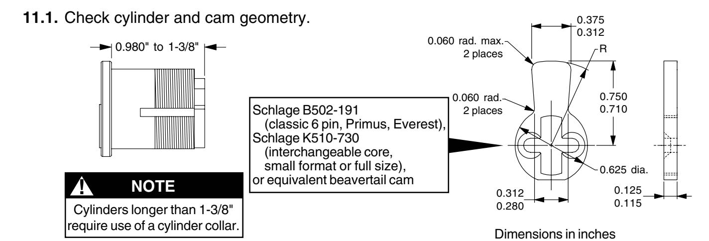
- 11.2. Make sure cylinder cam is in position for desired function with key removed (Figure 11-1). If not, remove cam and re-install in proper position.
- 11.3. Install cylinder into cylinder housing (Figure 11-2). Tighten cylinder retaining nut securely. Make sure end of cylinder housing marked "TOP" is up.

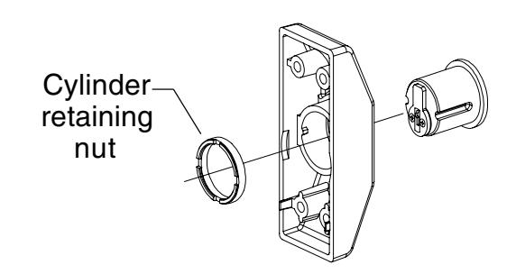
Figure 11-2
11.4. Install cylinder bracket (Figure 11-3). Install studs and screw where shown for RHR or LHR door. Make sure end of cylinder housing marked "TOP" is up.
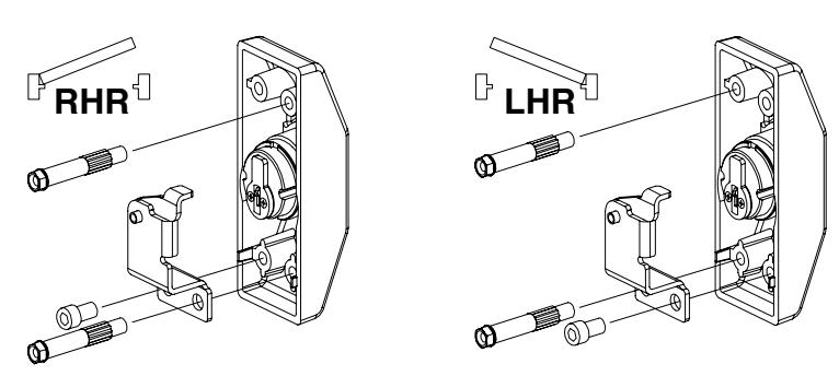
Figure 11-3
11.5. With top latch bolt released and facing up (Figure 11-4), position bottom of cylinder lift bracket 5/8" down from step in cutout (Figure 11-5). Maintain 5/8" location and tighten cylinder lift bracket mounting screws securely.
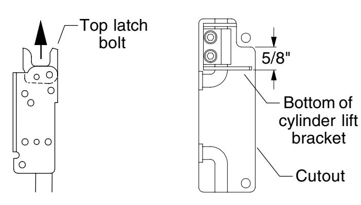
Figure 11-4
Figure 11-5
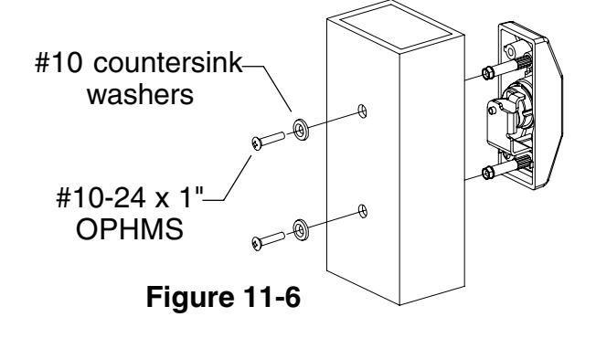
11.6. With key removed, install cylinder housing assembly on door (Figure 11-6). Secure with two #10 countersink washers and two #10-24 x 1" OPH machine screws.
12 Perform functional check.
- 12.1. Dog device (see page 17). Top latch bolt should pivot freely.
- 12.2. Undog device (see page 17) and trip top latch bolt so it faces up. Top latch bolt should not pivot.
- 12.3. If cylinder housing is installed, insert key and rotate 180° for NL or 360° for HB. Top latch bolt should pivot freely. For HB, key should come out of cylinder after clockwise rotation. For both NL and HB, rotate key back counterclockwise to starting position and remove key.
- 12.4. With device undogged (touchbar and key cylinder), press touchbar and release so top latch bolt locks forward and rods are held up. Bottom latch bolt should be flush to within 1/32" to bottom of door.
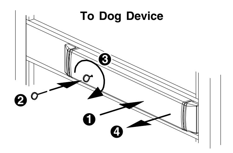
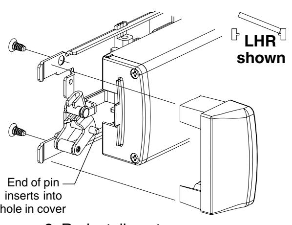
13 Install cover plate.
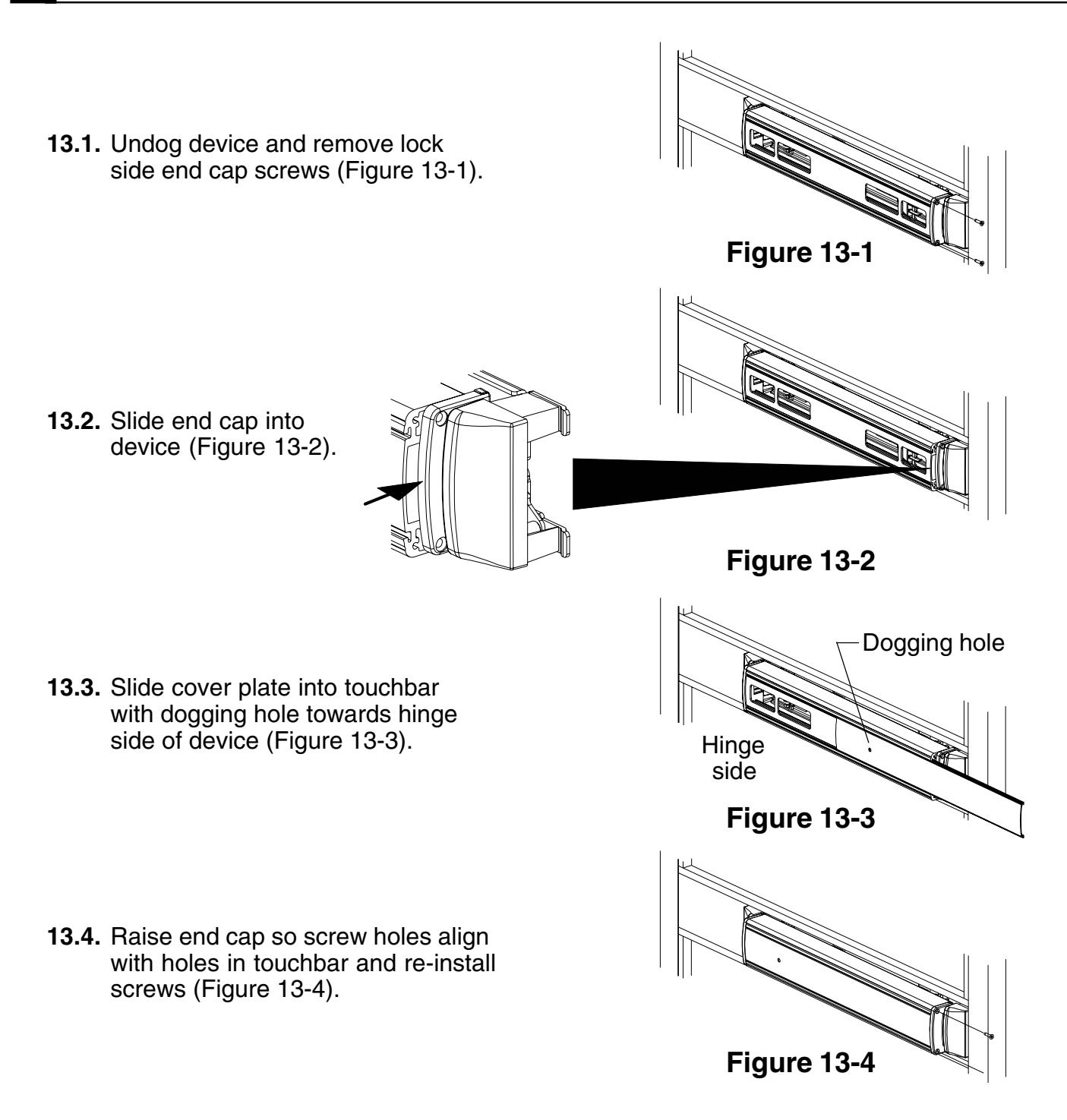
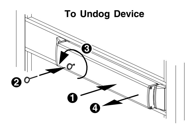
TOUCHBAR DOGGING
! NOTE
EL (electric latch retraction) devices cannot be dogged using the touchbar. If mechanical hold back is required, use pull side HB key cylinder option.
To Dog Device (latch stays retracted)
- 1. Depress touchbar with hand and hold in.
- 2. Insert dogging key into hole on touchbar.
- 3. Rotate key approximately 1/8 turn clockwise.
- 4. Release touchbar. Touchbar will remain depressed.
To Undog Device (latch locks when door closes)
- 1. Depress touchbar with hand and hold in.
- 2. Insert dogging key into hole on touchbar.
- 3. Rotate key approximately 1/8 turn counterclockwise.
- 4. Release touchbar. Touchbar will extend from door.
SETTING ROD LENGTHS
Rod lengths are factory set as specified on customer order. For configuring door for door height down to approximately 5.5 feet and up to approximately 10.5 feet, see 2390 Extension Rod Kit (part No. EXTROD.1001) or order rods from factory pre-set.
Determine top rod assembled length TR AL: TR AL = door height — C — 0.516" where C = distance from center line of muntin to bottom of door.
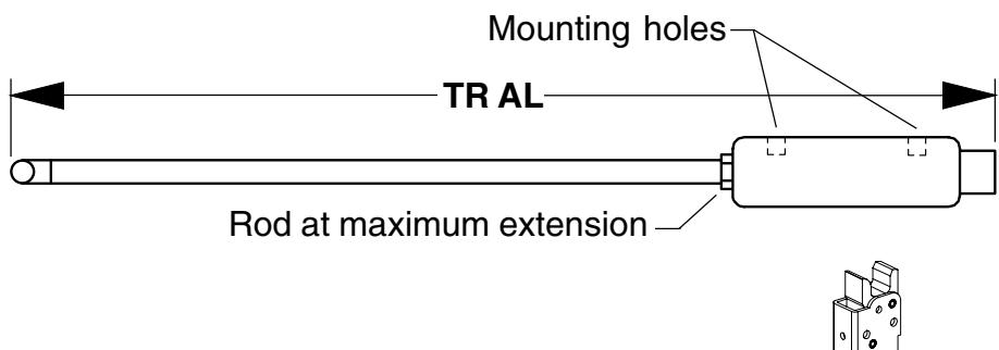
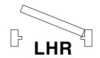
2. Set top rod to nearest 1/32" as determined in Step 1. Jam nut must be tightened so bent end of rod is perpendicular to sides of latch housing. See Figure 1 for handing. See table below for common rod lengths.
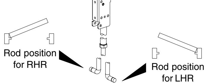
Figure 1
3. Determine overall bottom rod length BR: BR = C — 0.632"
where = distance from center line of muntin to bottom of door.
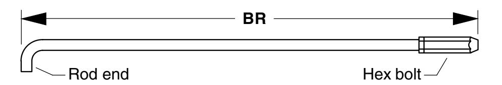
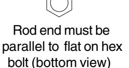
Figure 2
4. Set bottom rod to nearest 1/32" as determined in Step 3. Jam nut not required to be tight. End of rod must be oriented as shown in Figure 2 relative to flats on hex bolt.
For common rod lengths, see table below (all dimensions in inches).
| Door Height C (distance from center line of muntin to bottom of door) | BR | ||
|---|---|---|---|
| 83.188 (83-3/16) | 42.5 (42-1/2) | 40.176 (40-11/64) | 41.877 (41-7/8) |
| 83.188 (83-3/16) | 41.25 (42-1/4) | 41.426 (41-27/64) | 40.627 (40-5/8) |
| 83.188 (83-3/16) | 37.875 (37-7/8) | 44.801 (44-51/64) | 37.252 (37-1/4) |
| 83.188 (83-3/16) | 40 (40) | 42.676 (42-43/64) | 39.377 (39-3/8) |
| 83.250 (83-1/4) | 41.25 (41-1/4) | 41.489 (41-31/64) | 40.627 (40-5/8) |
RE-HANDING DEVICE
! NOTE
RHR to LHR conversion shown. To convert LHR device to RHR device, follow figures in reverse order, removing parts in Figures 6 through 4 and re-installing parts in Figures 3 through 1.
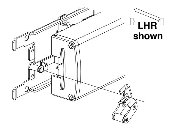
1. Remove lock side center case cover. 4. Flip device over and re-install lift arm.
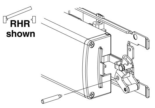
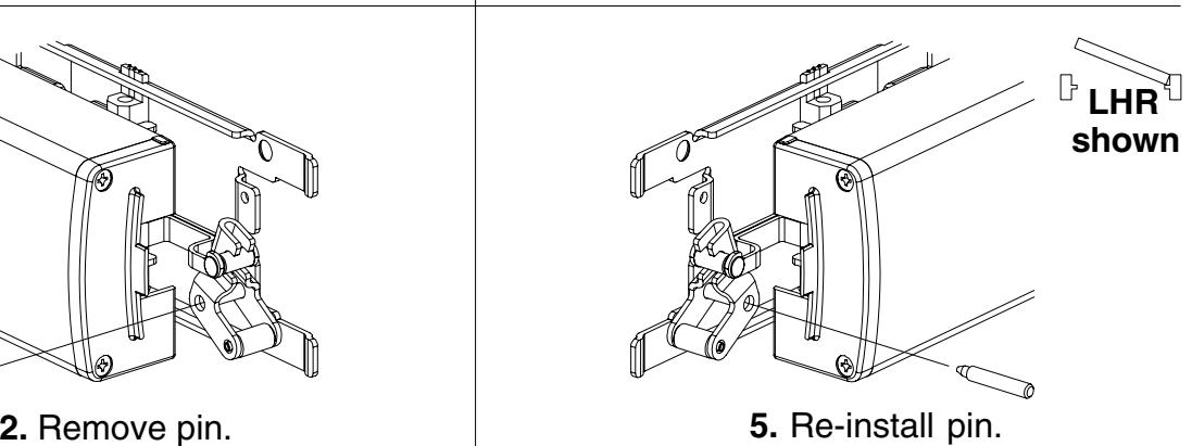
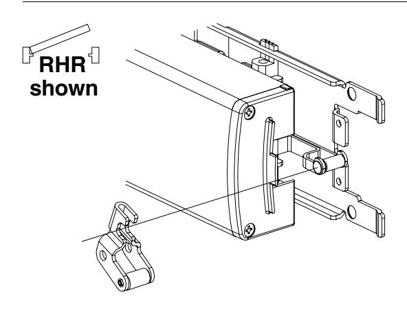
3. Remove lift arm. 6. Re-install center case cover.
TEMPLATE
Consult Falcon or door manufacturer for door-specific template information.
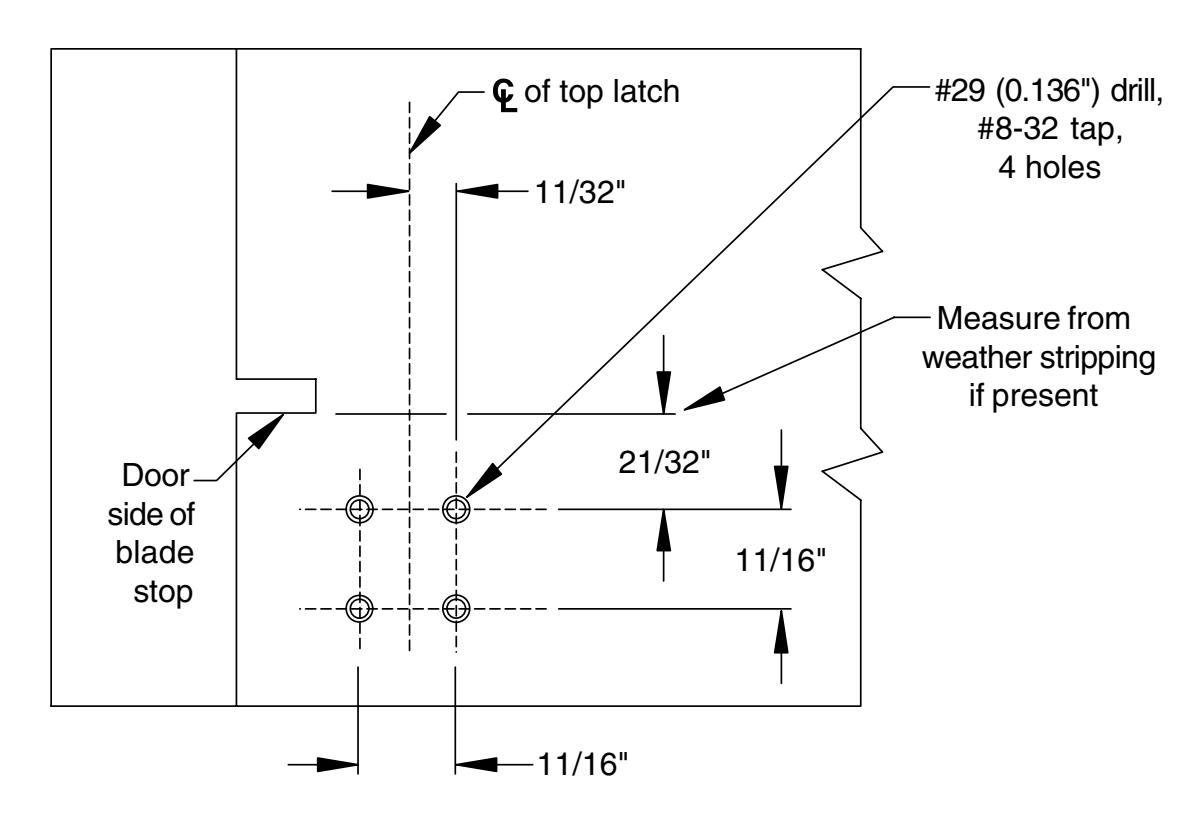
Bottom Plan View, Head Jamb (looking up) Showing Upper Strike Mounting Holes
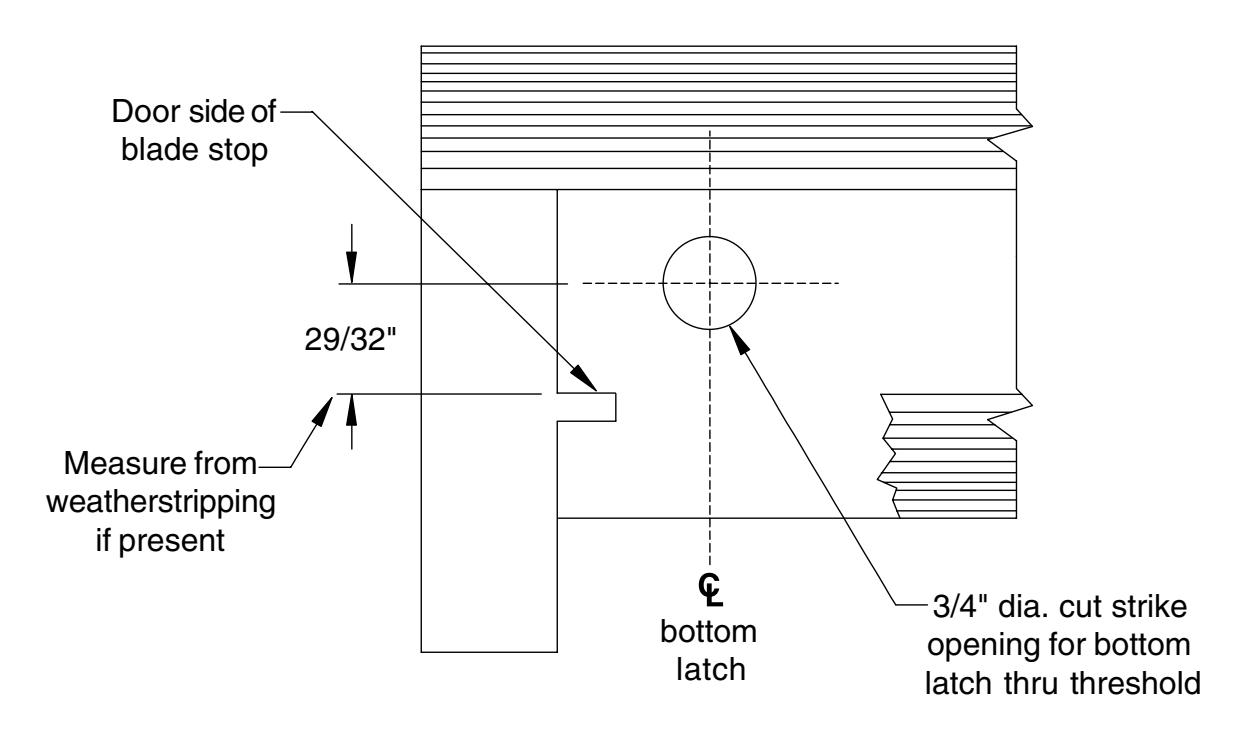
Top Plan View, Threshold (looking down) Showing Strike Cutout in Threshold for Latch