Falcon 2390 RX Switch Retrofit Kit Installation Instructions 108355
Open the original PDF document
View PDFFALCON ®
Installation Instructions

ININST.1043
1690/1790/2390 RX Switch Retrofit Kit
NOTE: This kit will work only with devices manufactured in June 2002 or later. See step 1 for determining manufacture date.
PARTS LIST
This switch is intended for signaling purposes only and is rated for a .1 ampere to 3 ampere resistive load at 24VDC/AC. Use with inductive or capacitive loads (magnetic locks or solenoid devices) derates the capacity of the switch. Consult the factory for assistance.
RX Switch and Bracket (1)

8-18 X 3/8" PPHSMS Screw (1)
1690/1790 INSTALLATION
Remove center case cover and check for date code sticker (Figure 1). If date code sticker is not present or date code is older than June 2002, RX switch cannot be used. See below to read date code
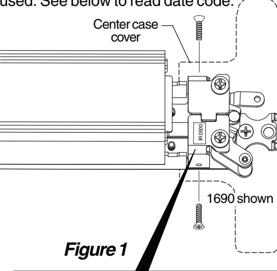
DATE CODE STICKER
Date code is in the form of month, year (i.e. 0500=May/2000)
If date code is not present, refer to Figure 2-2 for features that must be present for using kit
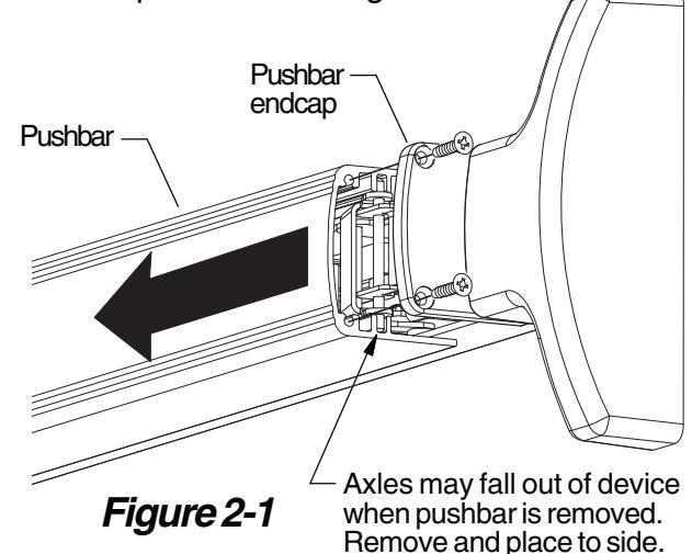
Remove pushbar endcap and slide pushbar off device (Figure 2-1). See Figure 2-2 for features that must be present for using RX kit.
Notch in connector bar Hole in bellcrank
Figure 2-2 Features for RX Kit

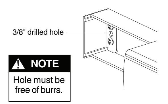
Drill 3/8" diameter wiring hole through channel end cap, channel, and inside face of door (Figure 3).
Screw RX switch bracket onto device as shown (Figure 4).
After installing, make sure that bell cranks operate freely and that switch bracket does not rub on connector bar
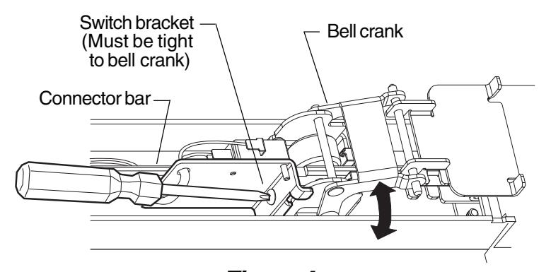
Figure 3
Figure 4
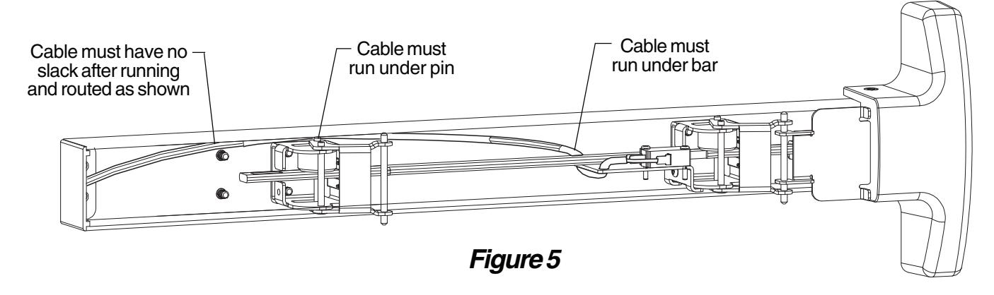
8 Route RX switch cable under bar and inside device channel as shown (Figure 5). If it is difficult to route wires along channel, it may be necessary to tape wire ends together.
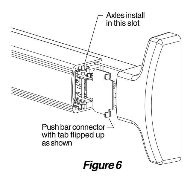
Reinstall pushbar onto device with axles in place and push bar connector flipped up as shown (Figure 6).
Reinstall pushbar endcap (Figure 7). See "RX Switch Wiring" on back cover for wiring information.
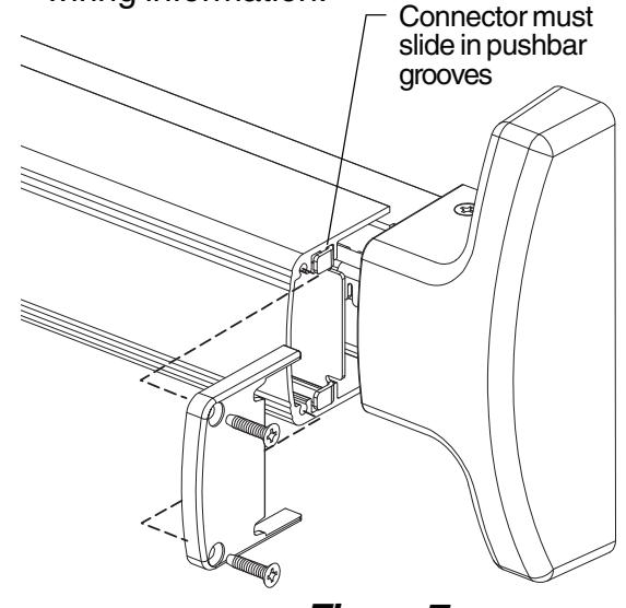
Figure 7
2390 INSTALLATION
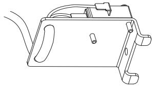
Remove two screws from lock stile end cap, then slide cover plate from device as shown (Figure 1-1).
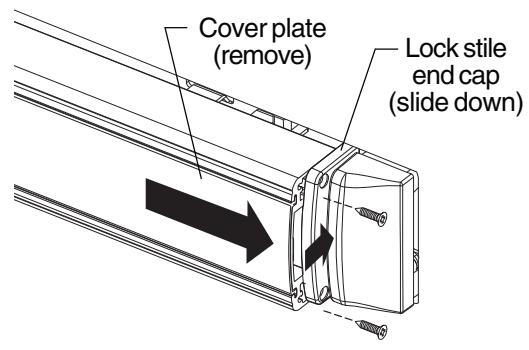
Figure 1-1
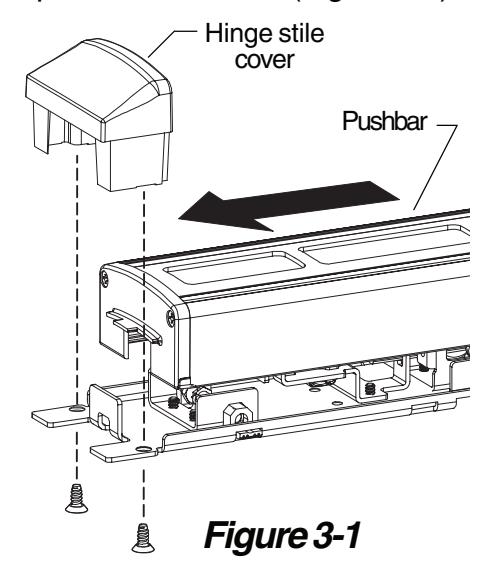
Remove hinge stile cover and slide pushbar off device (Figure 3-1).
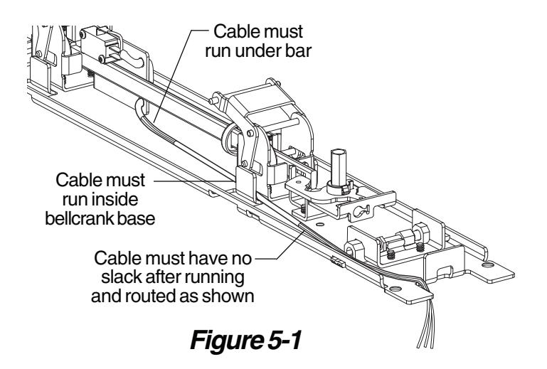
8 Route RX switch cable under connector bar and along base of device as shown (Figure 5-1).
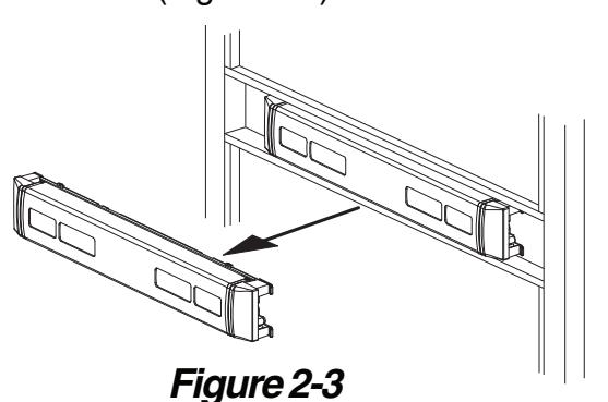
Follow instructions on back of cover plate or obtain ININST.1039 installation instruction from factory and remove device from door (Figure 2-3).
Screw RX switch bracket onto device as shown (Figure 4-1).
After installing, make sure that bell cranks operate freely and that switch bracket does not rub on connector bar
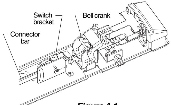
Figure 4-1
Drill 3/8" hole in door as shown to route wiring through (Figure 6-1). See "RX Switch Wiring" on back cover for wiring information.
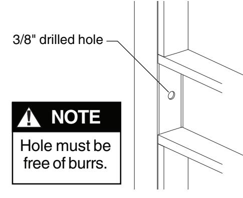
Figure 6-1

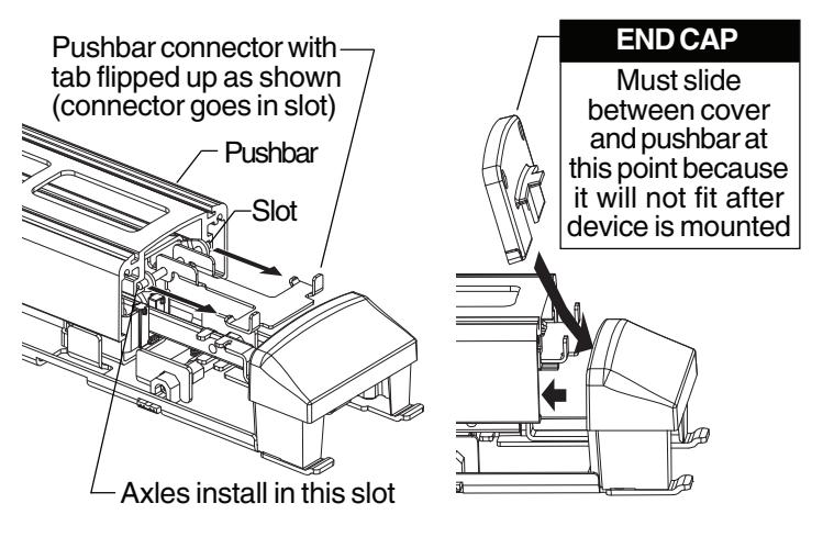
Figure 7-1 Figure 7-2
Install hinge stile cover (Figure 8-1) and reinstall device to door. After device installation, slide cover plate back onto pushbar, and secure lock stile pushbar endcap with two screws (Figure 8-2).
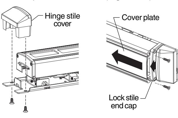
Figure 8-1 Figure 8-2
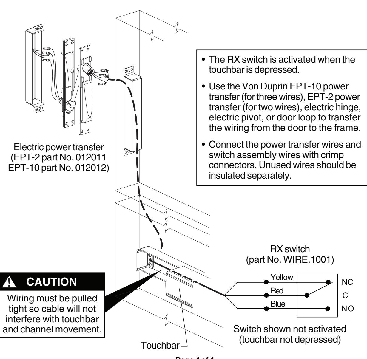
RX SWITCH WIRING
Page 4 of 4