Falcon 2090 Series Rim Panic Device Installation Instructions-English 107298
Open the original PDF document
View PDF

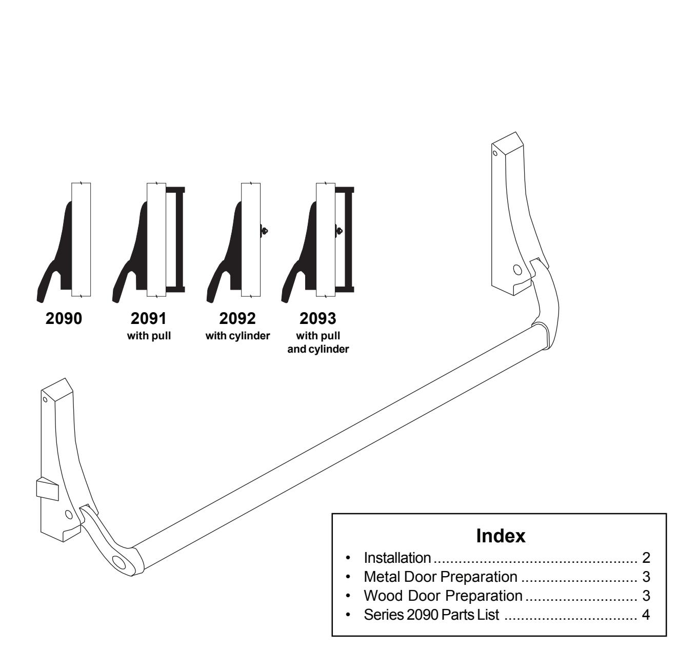
2090
4270101872
Rim Panic Device Installation Instructions
NOTES
- 1. Handing of device cannot be changed.
- 2. Crossbar length equals the distance between the housing vertical center lines minus 1-3/4".

INSTALLATION
- 1. Check "Series 2090 Parts List" (see page 4).
- 2. Prepare door for device (see page 3).
NOTE
Dimensions on lock and lock screw holes will function with the following 5-pin tumbler rim cylinders: Corbin, Lockwood, Schlage, Welch, Yale.
For other brands, refer to lock maker's template.
3. Aluminum and hollow metal doors: Install housing mounting studs in door.
Wood door: Install assembly plates in door cutouts.
- 4. Install cylinder if used. If required, cut tailpiece (Figure 1). Cylinder screw heads must be flush with door surface.
- 5. If cylinder is used, set pinion cam on back of active housing for hold-back (HB) or night latch (NL) operation (Figure 2).
Hold-back (HB): Turning key one complete rotation retracts latch bolt. If key is removed in this position, latch bolt stays retracted. Returning key to original position before removing allows latch bolt to extend.
To set for hold-back: Turn pinion cam until latch bolt starts to retract, then turn pinion cam the other way as far as it will go. Leave pinion cam in this position.
Night latch (NL): Turning key as far as it will go retracts latch bolt. Key must be returned to original position to be removed, leaving the door locked.
To set for night latch: Turn pinion cam until latch bolt starts to retract. Leave pinion cam in this position.
- 6. Install active housing over mounting studs and tighten set screws (Figure 3).
- 7. Check lever arm operation to ensure that all parts move freely. If cylinder is used, check that the cylinder functions correctly for either hold-back or night latch.
- 8. Install crossbar and inactive housing (Figure 4). Tighten inactive housing set screws and fasten crossbar with Taptite screws (item No. 16 in "Series 2090 Parts List," page 4).
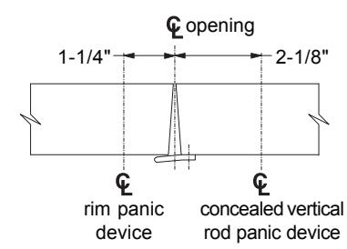
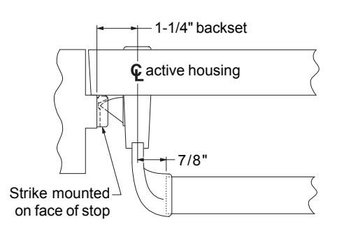
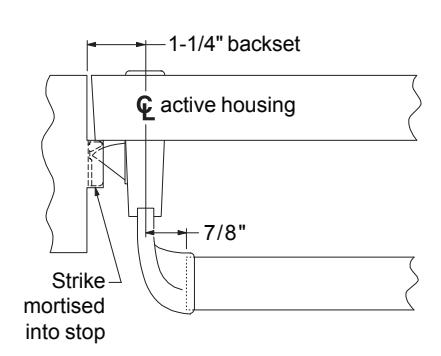
- 9. Prepare frame for strike and install strike (see bottom of page 4).
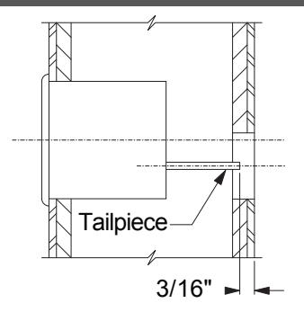
Figure1
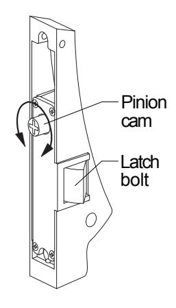
Figure2
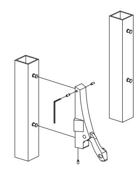
Figure3
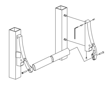
Figure4
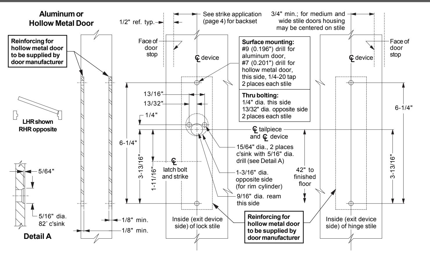
METAL DOOR PREPARATION
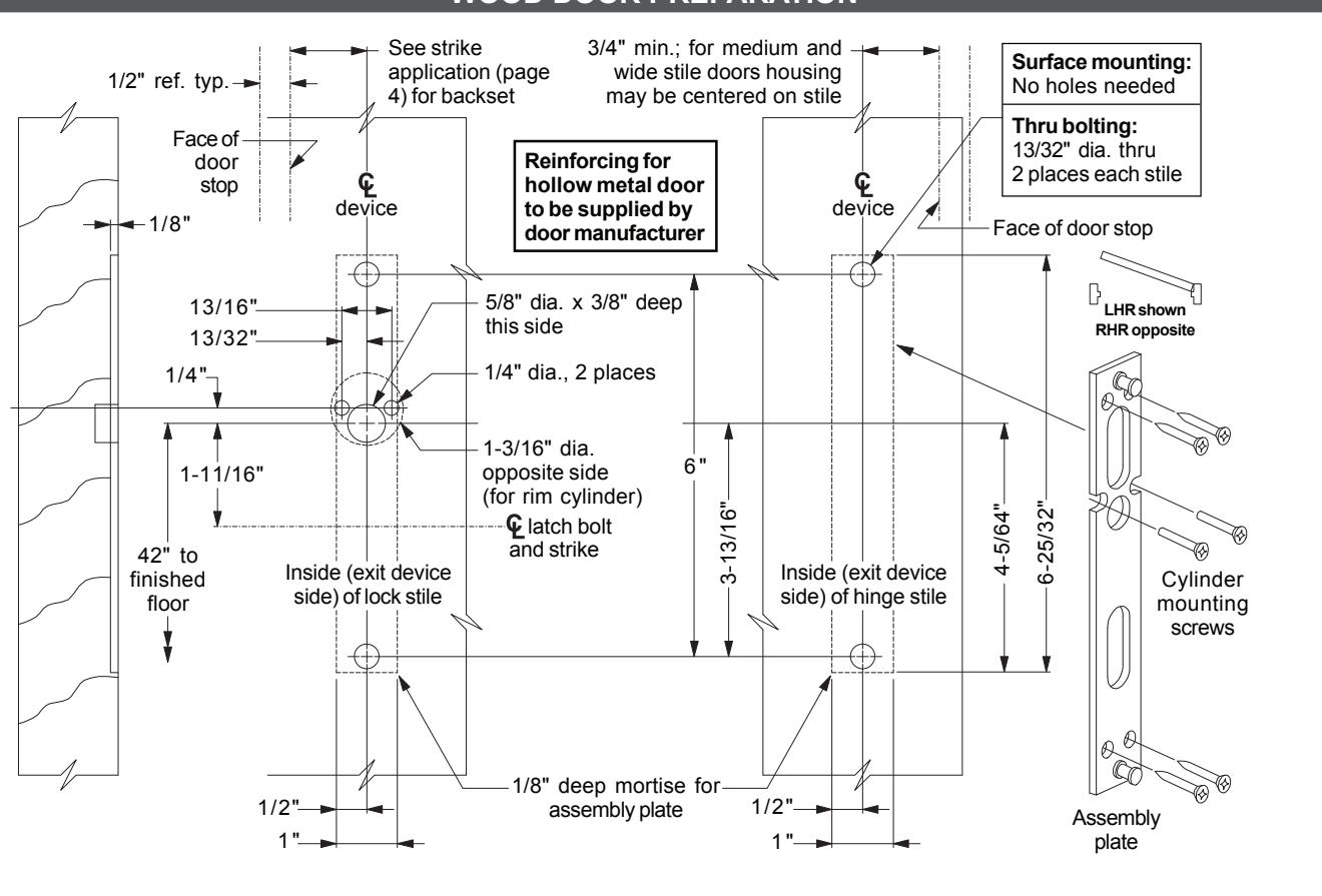
WOOD DOOR PREPARATION
SERIES 2090 PARTS LIST
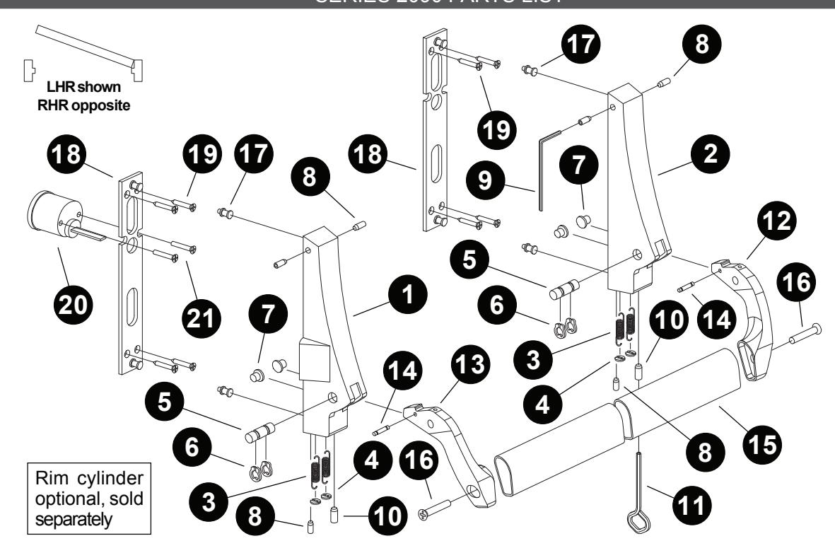
Item Qty. Description
- 1 1 Housing, active (RHR or LHR)
- 2 1 Housing, inactive (RHR or LHR)
- 3 4 Tension spring
- 4 2 Spring retainer
- 5 2 Axle pin
- 6 4 Retaining ring
- 7 4 Axle bushing
Item Qty. Description
- 8 6 1/4-20 x 3/8" socket head set screw
- 9 1 1/8" Allen wrench
- 10 2 7/16-14 x 3/4" socket head set screw
- 11 1 Dogging key
- 12 1 Lever arm, LH
- 13 1 Lever arm, RH
- 14 2 Spring pin
Item Qty. Description
- 15 1 Crossbar
- 16 2 1/4-20 x 1" Taptite
- 17 4 Housing mounting stud (metal doors)
- 18 2 Assembly plate (for wood doors)
- 10 8 #10 x 1" FPHSMS (for wood doors)
- 20 1 Rim cylinder 21 2 Rim cylinder screws
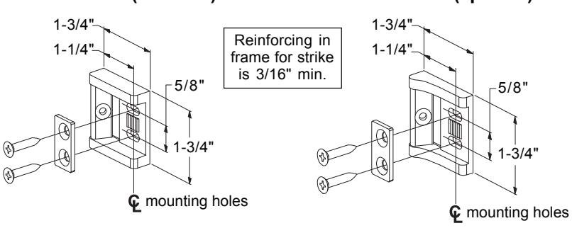
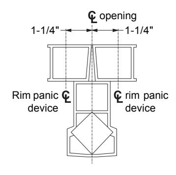
SD36Strike(standard) SD35Strike(optional) DoubleDoorswithSTK45Strike
SurfaceMountedStrike
MortisedStrike
Double Doorswith RM70 Mullion