Falcon 20 Series Surface Vertical Exit Device Installation Instructions 112161
Open the original PDF document
View PDF


47260189
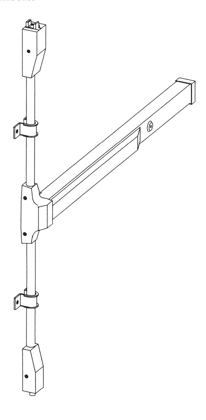
20 Series Surface Vertical Exit Device
Panic/Fire Surface Vertical Rod Exit Device
Installation Instructions

These instructions are presented in step by step sequence. Attach a template with tape to your door and frame as an aid to prepare for device mounting.
To determine door handing, please see "Door Handing" on page 3.
Please read instructions thoroughly before installation.
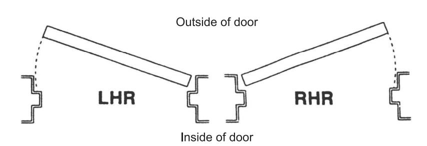
Door Handing
Use this diagram to determine the hand of the door.
Door Applications
Single Door
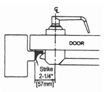
One rim exit device
Double Door with Mullion
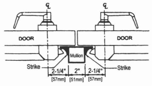
Two rim exit devices with mullion
Double Door without Mullion
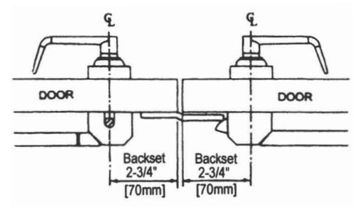
Rim exit device and surface vertical rod exit device combination

Prepare the door,
- a. Mark position of holes on the door using the templates. See Figure 1.
- b. Spot and drill all holes as marked on door for device chassis, top and bottom latch mounting brackets and end cap bracket.
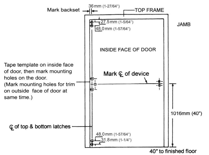
Standard centerline height of device is 40" above the finished floor.
Figure 1
2
Install brackets, device and trim.
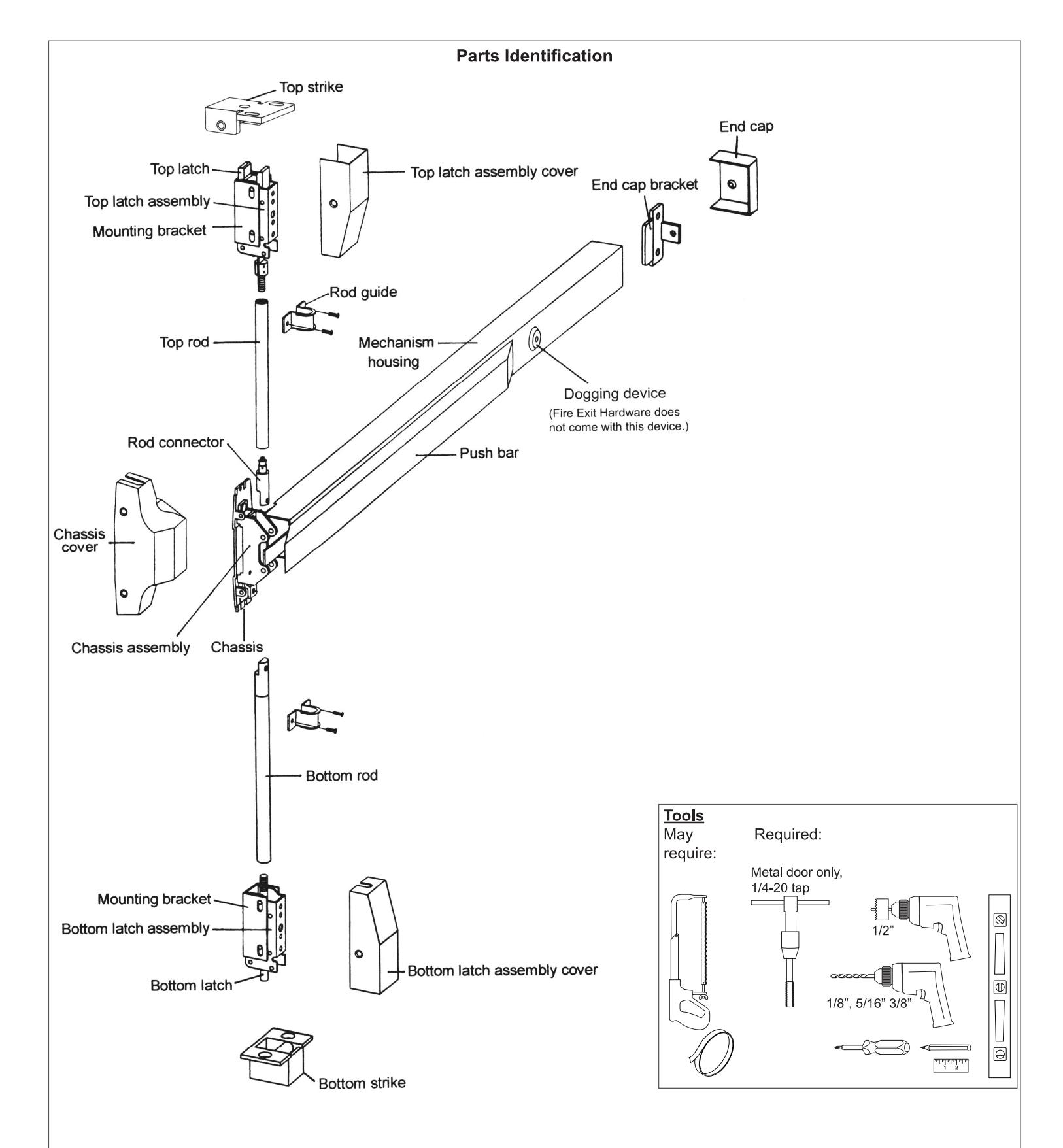
- a. Remove chassis cover from chassis assembly and end cap from end cap bracket.
-
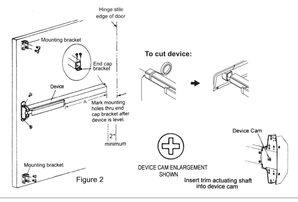
b. Cut device length if required.
- Devices are precut for a 36" (91.4 cm) door width or 48" (101.6 cm) door width. For 36" or 48" door width, no cutting is required. Skip to next step.
- If narrow door installation is required, cut device "A" equal to door width minus 4 inches (102 mm) to fit properly. If cutting is necessary, device must be cut clean and all burrs removed for proper end cap fit.
- c. Mount device horizontally to the drilled position securely using supplied mounting screws. Device may be bolted to trim with sex bolts if required. (See trim installation instructions for details.)
- d. Make sure to line up trim actuating shaft (tailpiece) with cam located on back of device chassis. See cam illustration below.
- e. Install end cap on device and mount to the door. Make sure the device is level.
- f. Install mounting brackets on the top and bottom of the door. (See Figure 2.)
Install bottom rod and bottom strike.
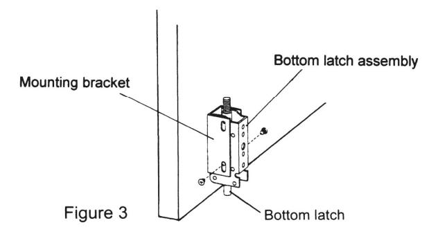
a. Mount bottom latch assembly into mounting bracket. (See Figure 3.)
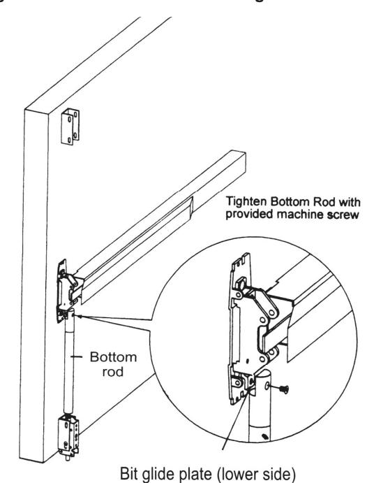
b. Fasten the driving pin into the upper side of bit glide plate. (See Figure 4.)
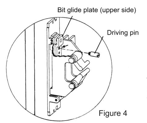
The driving pin is mounted on the hole as the arrow marked.
c. Screw the threaded end of bottom rod into bottom latch assembly. (See Figure 5.)
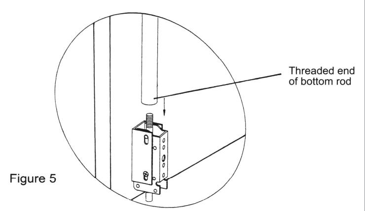
- d. Tighten bottom rod with bit glide plate in bottom position. (See Figure 6.)
- If the hole on bottom rod connector does not match alignment with the mounting hole of bit glide plate, adust height of bottom rod as shown at Figure 5.
(.....
Figure 6
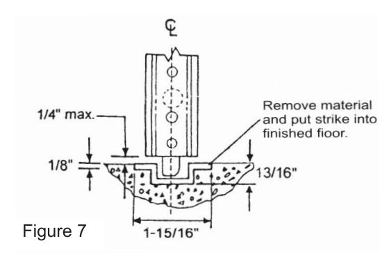
- e. Install bottom strike into finished floor. Be sure to align centerline of bottom latch with centerline of bottom strike. (See Figure 7.)
- f. Depress push bar and release to check for correct installation.
- g. Make sure bottom latch can be held retracted and flush with edge of door when push bar is depressed.
- h. Check bottom latch bolt to make sure it has 15/16" (9.5 mm) minimum throw when push bar is released.

Install top rod and top strike.
- a. Mount top latch assembly into mounting bracket. (See Figure 8.)
- b. Screw the full length of threaded end of top rod into top latch assembly. (See Figure 9.)
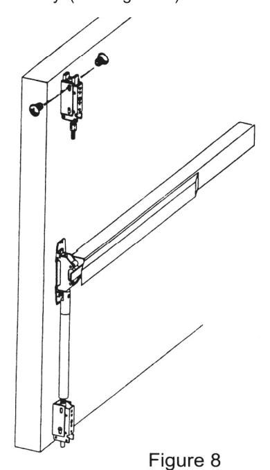
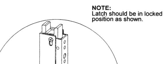
Figure 9
Threaded end of top rod
- Measure the top rod against the edge of the rod connector as shown. Mark the rod and cut off excess. (See Figure 10.)
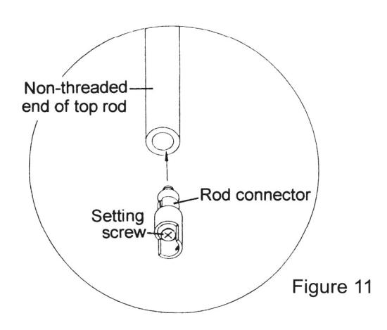
- d. Insert the rod connector into the non-threaded end of the top rod and tighten set screw securely. (See Figure 11.)
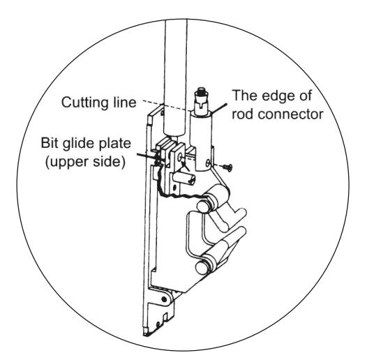
Figure 10
- e. Tighten top rod connector onto the bit glide plate (upper side). (See Figure 12.)
- f. If the hole of top rod connector does not align with the mounting hole of the bit glide plate, then adjust the length of top rod as shown at Figure 9, or make an additional cut to adjust the length.
- g. Mark mounting holes for top strike on door jamb using the strike template. (See Figure 13.)
- h. Fasten the top strike using the supplied screws. (See Figure 14.)
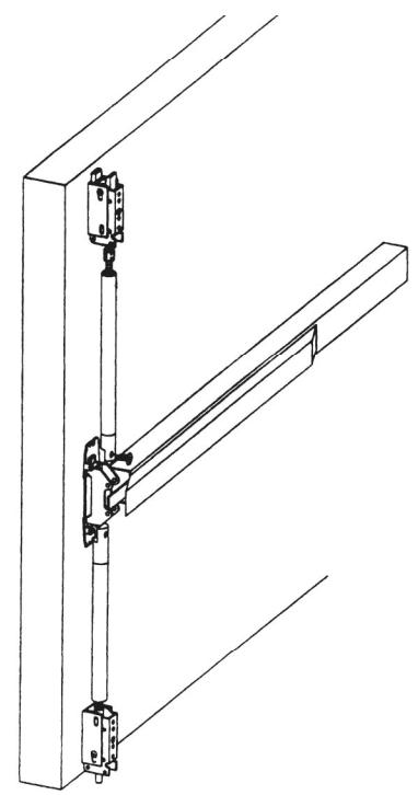
Figure 12
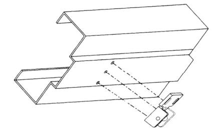
Figure 13
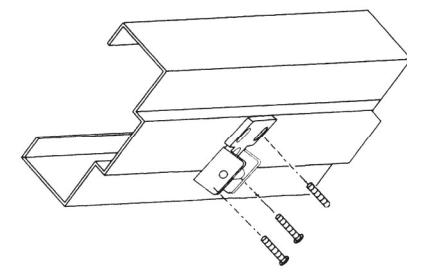
Figure 14
5
Test operation.
- Depress push bar. Top latch should be held retracted. While top latch is retracted the bottom latch must clear floor and bottom strike simultaneously to open door.
- b. Release push bar. Both top latch bolt and bottom latch bolt should be fully extended.
- c. Check device operation by depressing and releasing push bar several times to assure correct installation.
- d. Repeat device operation by opening and closing door several times with outside trim to assure correct installation.
If top latch bolt is not held retracted, or if bottom latch bolt does not clear floor and strike, repeat the adjustment procedure. See "Install top rod and top strike." on page 6 or "Install bottom rod and bottom strike." on page 5 for details.

Install covers.
- a. Before installing covers, secure latch bolts and adjust strikes if necessary. (See Figure 15.)
- Install chassis cover, end cap, and top and bottom latch covers.
- c. Install two rod guides as shown. Position rod guides midway between center case and latch.
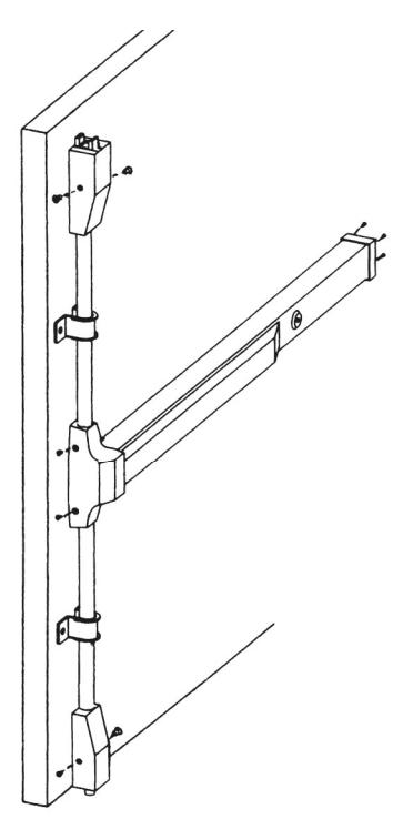
Figure 15

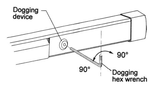
Dog the device.
Dogging the device during high traffic periods will extend the life of the device. (Dogging is not available on fire rated models as fire doors must remain closed and latched.)
Dogging: Depress push bar, insert dogging hex wrench and turn clockwise 90 degrees. The push bar will remain depressed and the latch will remain retracted.
Release dogging: Hold push bar, insert dogging hex wrench and turn counterclockwise 90 degrees. The push bar will return to the up position and latch will extend to lock the door.