Falcon 20 Series Rim Exit Device Installation Instructions 112160
Open the original PDF document
View PDF


47260188
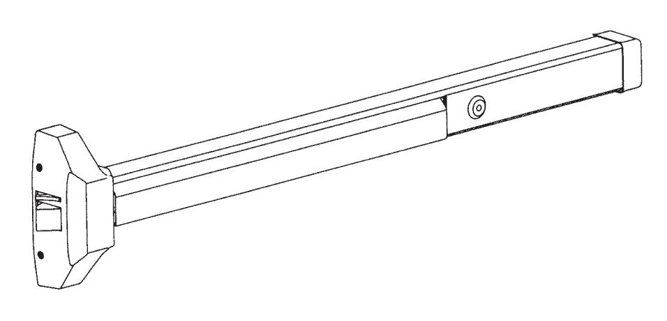
20 Series Rim Exit Device
Reversible Panic/Fire Rim Exit Device
Installation Instructions
Parts Identification

These instructions are presented in step by step sequence. Attach a template with tape to your door and frame as an aid to prepare for device mounting.
Please read instructions thoroughly before installation.
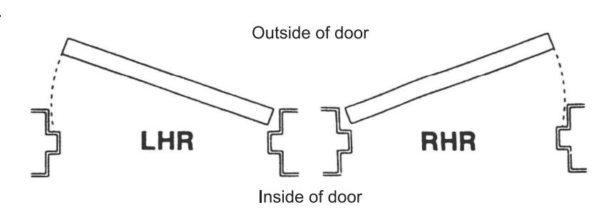
Door Handing
Use this diagram to determine the hand of the door.
Door Applications
One rim exit device
Single Door
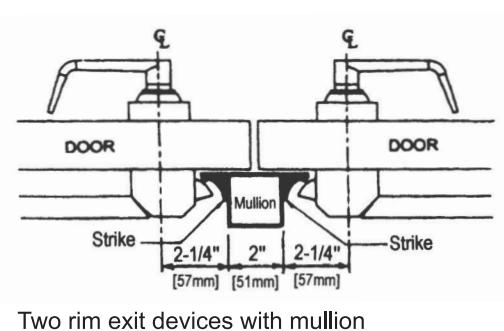
Double Door with Mullion
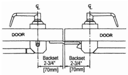
Double Door without Mullion
Rim exit device and surface vertical rod exit device combination
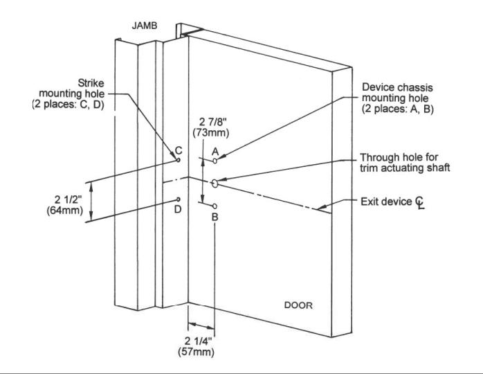
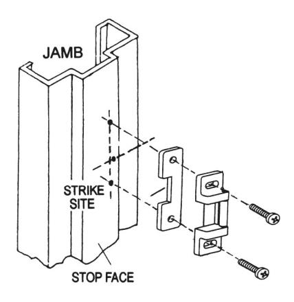
Mark and drill mounting holes.
- a. Mark centerline of exit device by marking a line across the door and stop 40" (101.6 cm) above finished floor as
- b. Apply template to the door and align centerlines on template with centerlines on door. Mark location of two (2) exit device mounting holes as shown on template.
- c. Move template against door stop. Mark two (2) mounting holes for strike holes for panic device, or three (3) holes for a fire rated device.
- d. Drill holes.
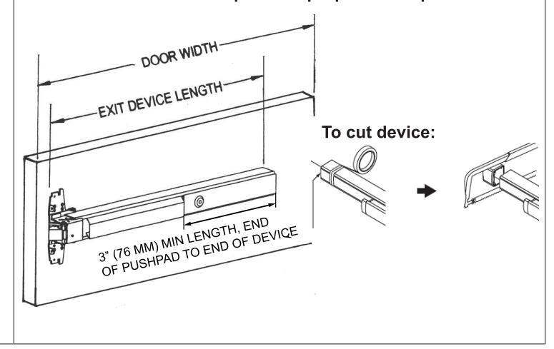
Measure and cut device to length.
The exit device has two size options, one for a 36" (91.4 cm) door width and one for a 48" (122 cm) door width.
For 36" or 48" door width, no cutting is required. Skip to next step.
- a. Measure door opening (door width).
- b. Measure exit device length NOT INCLUDING end cap.
- c. Exit device length must be 4" (102 mm) shorter than door
- d. If necessary, cut the exit device to appropriate length.
- Be sure the end of device body and cover plate are flush before cutting.
- · Device must be cut square for proper end cap fit.
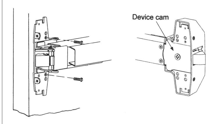
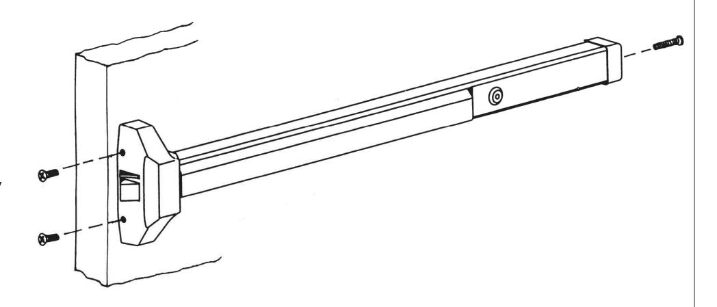
Install device body.
- Remove chassis cover from device chassis. Mount device body horizontally to the drilled position using supplied mounting screws or sex bolts.
- b. If using trim, be sure to line up trim actuating shaft (tailpiece) with cam located on back of device chassis. See trim installation instructions and template for more details.
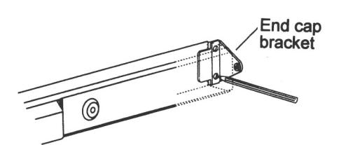
Install end cap.
- Remove end cap from end cap bracket. Mark hole locations by either using template or holding end cap bracket lip on end of device body.
- b. Mark, drill and tap two mounting holes.
- c. Install end cap bracket and end cap.
4
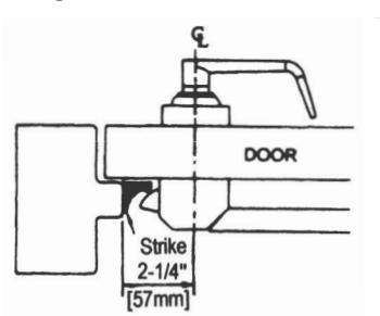
Install strike.
- For panic rated rim exit device: 1/8" (3 mm) strike shim is for prepared door with 1/2" (13 mm) stop. Shim is mounted beneath strike. If stop is 5/8" (16 mm) shim is not necessary.
-
For fire rated rim exit device:
Strike is installed without strike shim.
- a. Place strike at drilled postion. Mount with supplied screws.
- Open and close door to verify latch bolt and dead latch are properly aligned.
- Adjust strike if necessary before tightening mounting screws.
- d. For fire rated strike only, secure center screw.
5
Test operation and install covers.
-
a. Test push bar operation before installing cover.
- Device with no trim: The door should open smoothly when the pushbar is pressed.
- Device with trim: The door should open smoothly when key or lever/knob is operated.
- b. Install chassis cover and end cap using supplied screws.

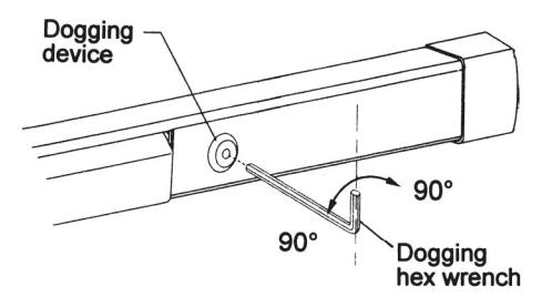
Dog the device.
Dogging the device during high traffic periods will extend the life of the device. (Dogging is not available on fire rated models as fire doors must remain closed and latched.)
Dogging: Depress push bar, insert dogging hex wrench and turn clockwise 90 degrees. The push bar will remain depressed and the latch will remain retracted.
Release dogging: Hold push bar, insert dogging hex wrench and turn counterclockwise 90 degrees. The push bar will return to the up position and latch will extend to lock the door.