Falcon 1990 Series Concealed Vertical Rod Panic Device Installation Instructions-English 107297
Open the original PDF document
View PDF

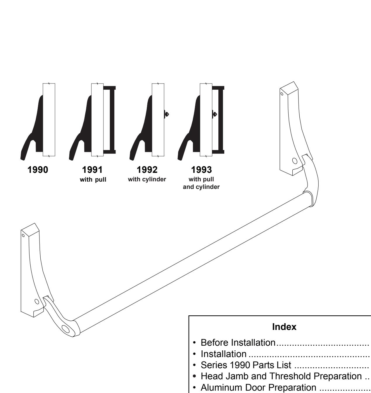
1990
4270101871
Concealed Vertical Rod Panic Device
Installation Instructions
• Hollow Metal Door Preparation ...............
Before Installation
- 1. Check "Series 1990 Parts List" (see page 5).
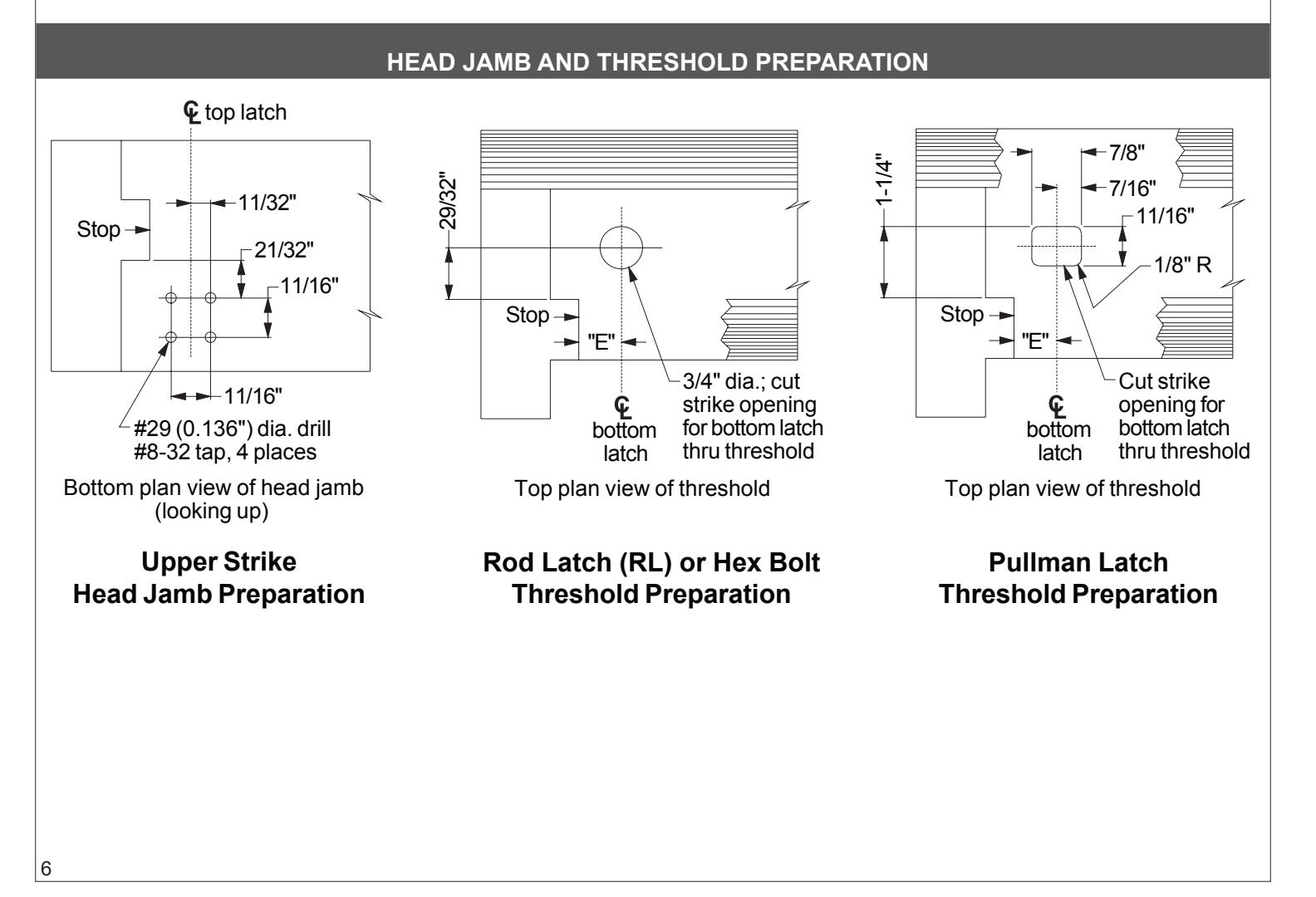
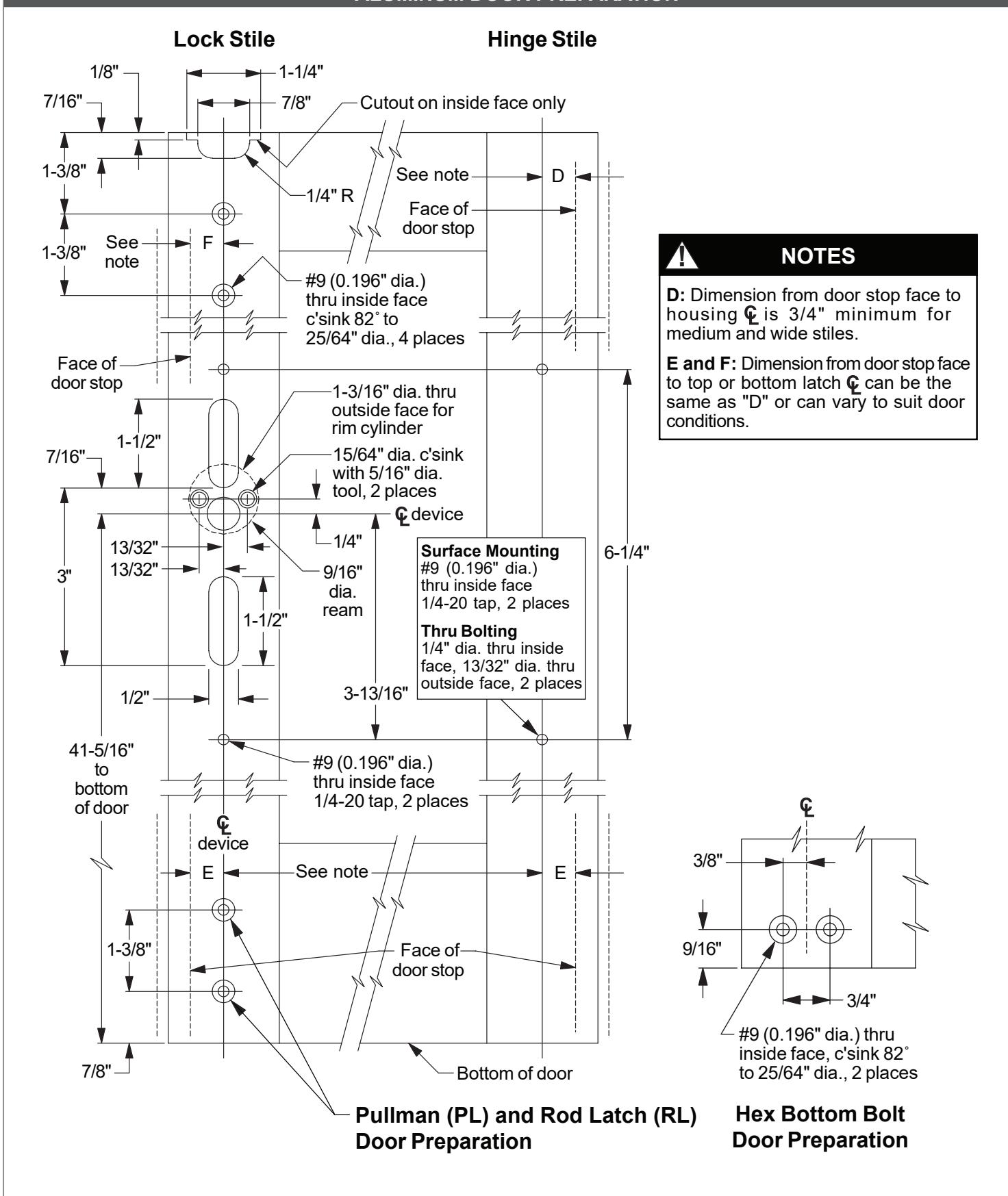
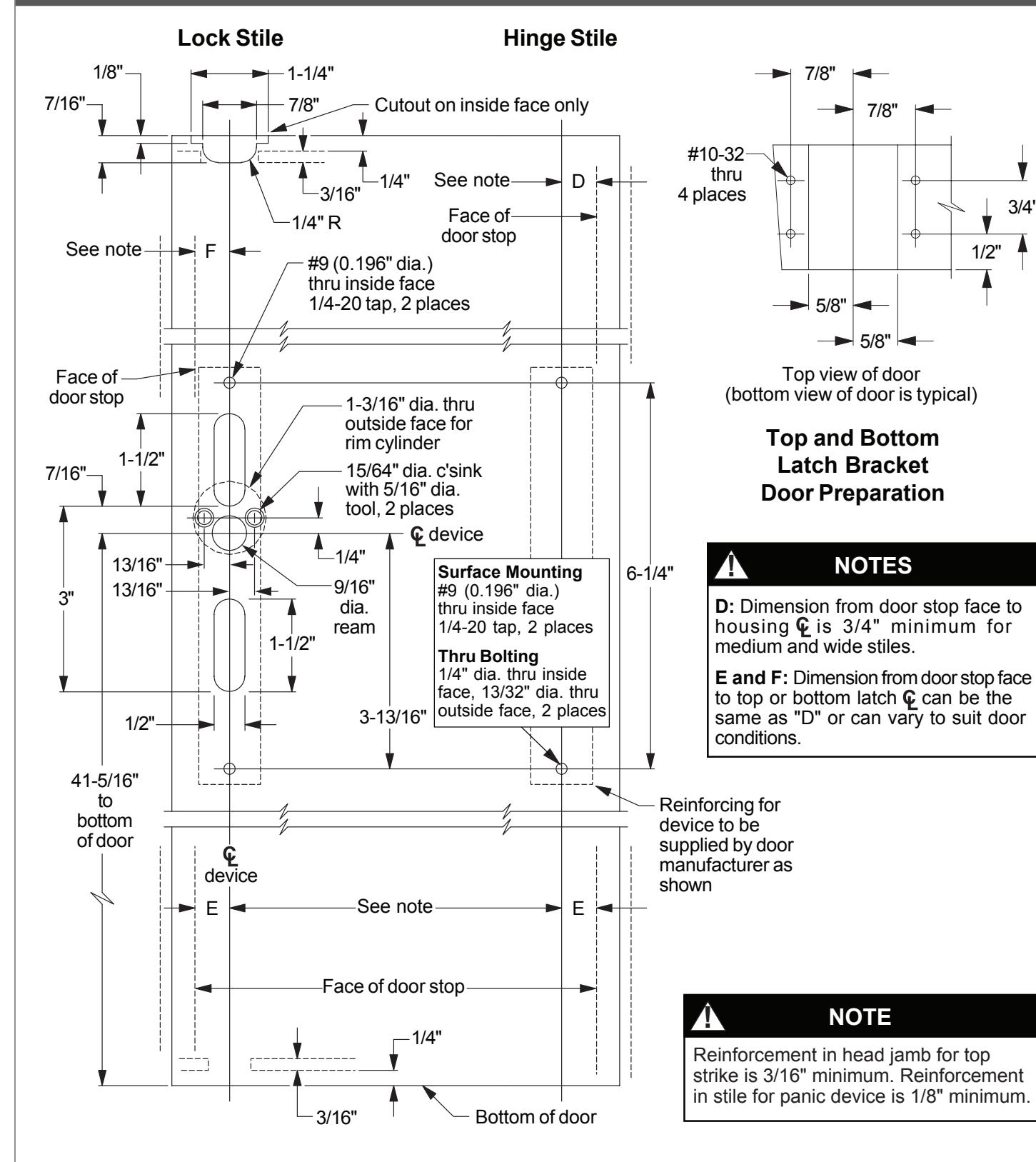
- 2. Prepare door, threshold, and head jamb: aluminum door page 7; hollow metal door page 8; threshold and head jamb page 6.
NOTES
- 1. Handing of device can be changed.
- 2. Latch mounting center lines need not be the same as the housing center lines. The operating rod can work at an angle to permit mounting of latches so they will clear projections inside the door.
- 3. Crossbar length equals the distance between the housing vertical centerlines minus 1-3/4".
INSTALLATION
1 Install rod assemblies.
- 1a For hollow metal door, attach latch brackets to sides of top and bottom latches with #10-32 x 1/4" UFPH machine screws (Figure 1-1).
- 1b Slide top rod assembly into door. Hollow metal door: Secure each latch bracket to door with two #10-32 x 3/8" FPH machine screws. Aluminum door: Secure top latch to door with two #10-32 x 1/4" UFPH machine screws through face of door into front mounting holes on latch.
- 1c Install bottom rod assembly into door. If using rod latch (RL) bottom rod assembly: For hollow metal door, secure each latch bracket to door with two #10-32 x 3/8" FPH machine screws; for aluminum door, secure top latch to door with two #10-32 x 1/4" UFPH machine screws through face of door into front mounting holes on latch.
- 1d For hex bottom rod, install hex rod guide in door with #10-24 x 3/8" UFPHTC screws (Figure 1-2).
- 1e Install rod bearing bushing over end of each rod and secure with retaining ring (Figure 1-3).
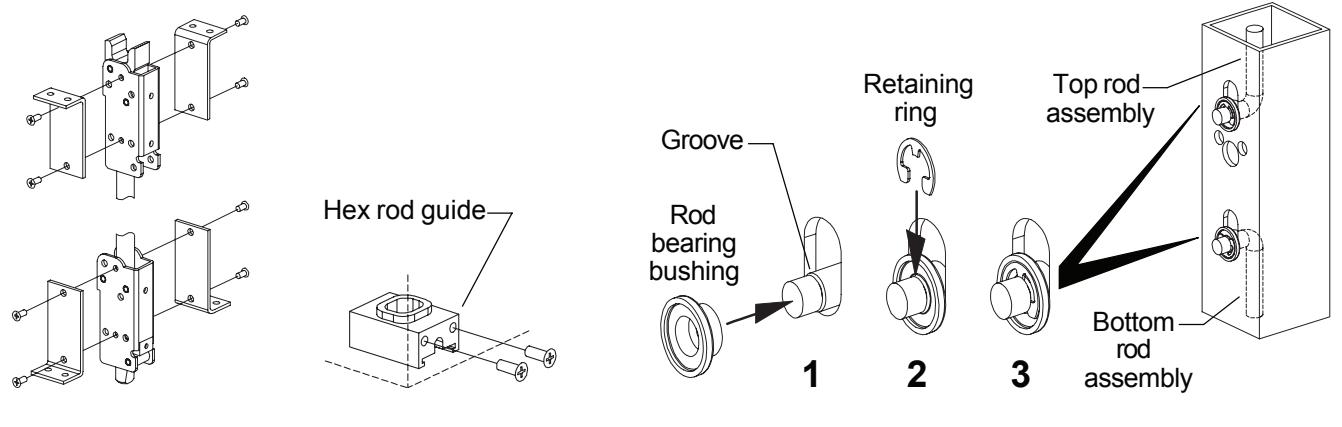
Figure 1-2
Figure 1-1 Figure 1-3
-
1f Check latch operation and rod length adjustment:
- a. Place traveler over rod ends.
- b. Slide traveler up. Top latch should release and hold rods in up position, and bottom latch should be completely retracted (flush with bottom edge of door).
- c. Move top latch back to locked position. Rods should drop down, locking top latch and extending bottom latch approximately 1/2".
- d. If necessary, adjust rod lengths for correct operation. Remove traveler after adjustment.
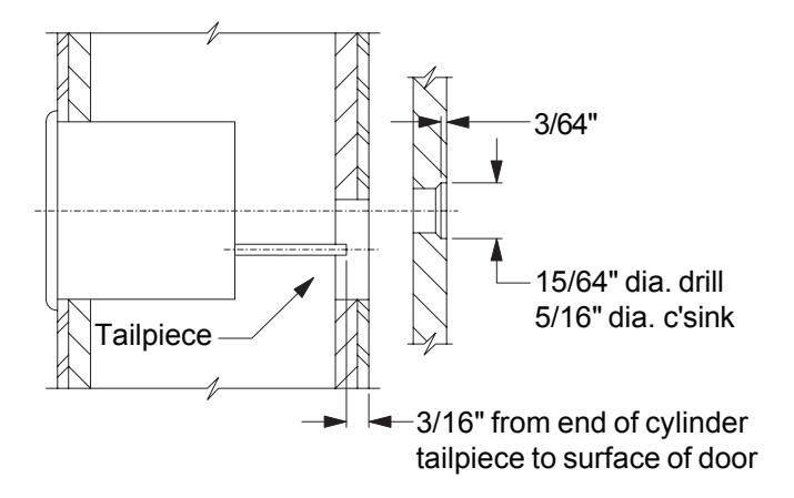
2 Install cylinder
Install cylinder. If required, cut cylinder tailpiece as shown. Heads of cylinder mounting bolts must be flush with door surface.
3 Install pinion cam and traveler.
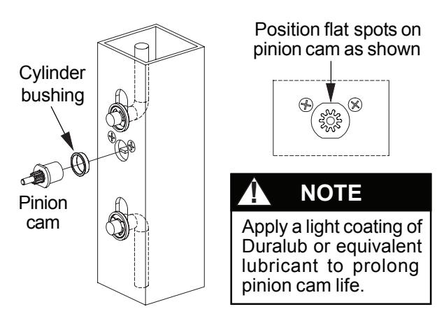
Figure 3-1
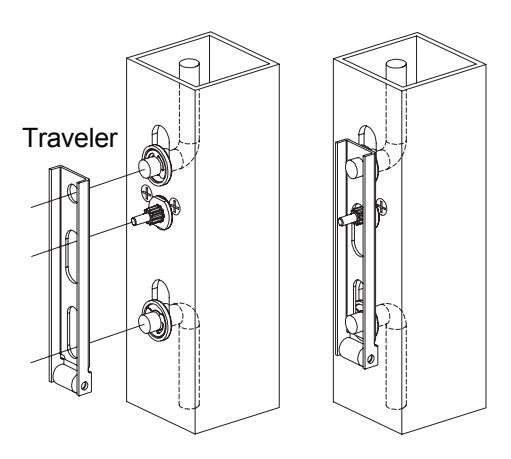
Figure 3-2
4 Install retractor.
Install retractor over pinion cam (Figure 4-1). Position retractor as shown in Figure 4-2 for holdback (HB) or night latch (NL) function.
Hold-back (HB) : Turning key one complete rotation retracts latch bolt. If key is removed in this position, latch bolt stays retracted. Returning key to original position before removing allows latch bolt to extend.
Night latch (NL) : Turning key as far as it will go retracts latch bolt. Key must be returned to original position to be removed, leaving the door locked.
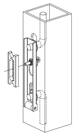
Figure 4-1
Hold-back (HB) Night latch (NL)
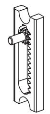
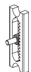
Install retractor with teeth to right as shown for both RHR and LHR doors; this makes all keys function in the same direction
Figure 4-2
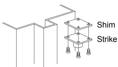
5 Install top strike.
Install top strike with four #8-32 x 1/4" flat head Phillips undercut screws. The top strike is fabricated off center to permit pin adjustment by rotating the strike 90°. Use strike shims (supplied with strike) as needed to adjust the projection of the strike pin.
6 Install housing mounting studs, housings, and crossbar.
- 6a Install four housing mounting studs (Figure 6-1).
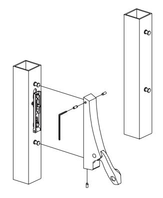
- 6b Install lock stile housing over mounting studs and secure with set screws (Figure 6-2). Test operation.
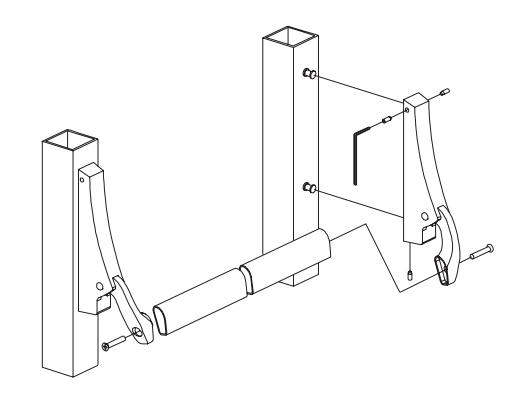
- 6c Install crossbar and hinge stile housing (Figure 6-3). Secure housing with set screws. Secure crossbar with two 1/4-20 x 1" Taptite screws.
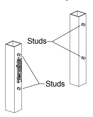
Figure 6-1 Figure 6-2 Figure 6-3
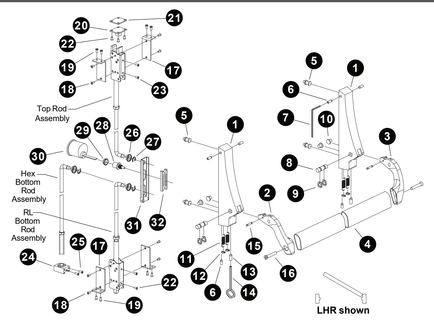
SERIES 1990 PARTS LIST
| Item | Qty. | Description | Item | Qty. | Description |
|---|---|---|---|---|---|
| 1 | 2 | Housing | 17 | 4 | Latch bracket(hollow metal doors only) |
| 2 | 1 | Lever arm, LH | 18 | 8 | #10-32 x 1/4" UFPHMS |
| 3 | 1 | Lever arm, RH | 19 | 8 | #10-32 x 3/8" FPHMS |
| 4 | 1 | Crossbar | 20 | 1 | PB48 strike |
| 5 | 4 | Housing mounting stud | 21 | 3 | PB48 strike shim |
| 6 | 6 | 1/4-20 x 3/8" hex socket head set screw | 22 | 4 | #8-32 x 1/2" UFPHTC |
| 7 | 1 | 1/8" Allen wrench | 23 | 4 | #10-32 x 1/4" UFPHMS |
| 8 | 2 | Axle pin | 24 | 1 | Hex rod guide |
| 9 | 4 | Retaining ring | 25 | 2 | #10-24 x 3/8" UFPHTC |
| 10 | 4 | Axle bushing | 26 | 2 | Rod bearing bushing |
| 11 | 4 | Tension spring | 27 | 4 | Retaining ring |
| 12 | 4 | Spring retainer | 28 | 1 | Pinion cam |
| 13 | 2 | 7/16-14 x 3/4" hex socket head dogging screw | 29 | 1 | Cylinder bushing |
| 14 | 1 | Dogging key | 30 | 1 | Rim cylinder (optional; sold separately) |
| 15 | 2 | Spring pin | 31 | 1 | Traveler |
| 16 | 2 | 1/4-20 x 1" Taptite | 32 | 1 | Retractor |
PARTS LIST (CONTINUED) TOP ROD ASSEMBLY SU latch 4270101806 Jam nut 3/8"-24 NUT.101 (Pkg of 10) Top rod: • Bent rod 35.125" long (7' door) 4270100017 (can be shortened by 5") • Bent rod 47.125" long (8' door) 4270100018 (can be shortened by 13") Optional ES (electric strike) top latch (not shown) 4270100346 ROD LATCH (RL) BOTTOM ROD ASSEMBLY Bottom rod: Bent rod 35.125" long 4270100017 (can be shortened by 5") RL bottom latch 4270100521 Jam nut 3/8"-24 NUT.101 (Pkg of 10) HEX BOTTOM ROD ASSEMBLY Hex bolt 4270101830 Optional PL (pullman) bottom latch (not shown) 4270101482 Bottom rod: Bent rod 37.812" long 4270101825 (can be shortened by 6") Jam nut 3/8"-24 NUT.101 (Pkg of 10)
ALUMINUM DOOR PREPARATION
HOLLOW METAL DOOR PREPARATION

3/4"