Falcon 1790 Touchbar Rim Panic Device Installation Instructions 107910
Open the original PDF document
View PDF

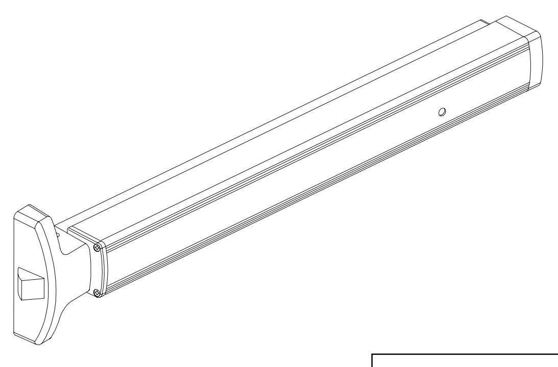
1790 Touchbar
ININST.1001
Rim Panic Device Installation Instructions
Index:

BEFORE INSTALLATION
- 1. Check "Parts List" (see page 16).
- 2. Prepare door using template on page 14.
- 3. Prepare frame using template on page 15.
- 4. If door width is non-standard, cut device (see page 10).
INSTALLATION
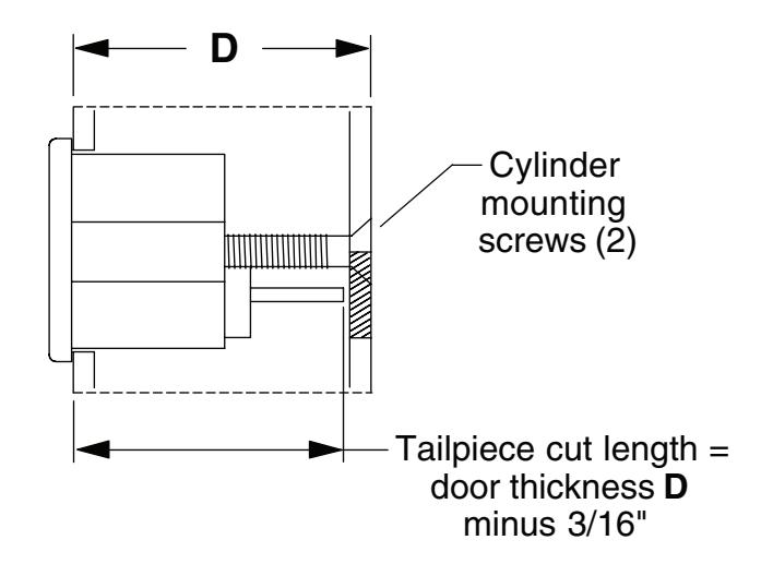
Install outside cylinder. (If no outside cylinder, go to Step 3.)
1.1. Cut cylinder tailpiece to correct length.
Â
NOTE
If 5/32" spacer is used, as in Kawneer applications, cut length is 1-23/32" for a 1-3/4" thick door.
1.2. Install cylinder into door and secure with two mounting screws. Screws must be flush with surface of door.
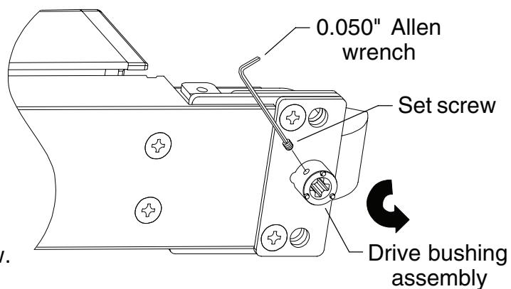
2 If necessary, change key function to hold back (HB).
À
NOTE
Device is set at factory for night latch (NL) function. To convert to HB, perform Steps 2.1-2.3. For NL function, skip Steps 2.1-2.3 and go to Step 3.
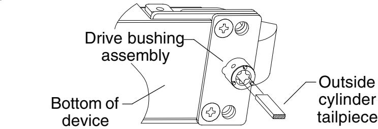
- 2.1. Remove the set screw from the drive bushing assembly using 0.050" Allen wrench supplied in PKG.133.
- 2.2. Rotate internal drive bushing counterclockwise until it stops against the internal stop.
- 2.3. Maintain position of drive bushing and continue. Do not reinstall set screw.
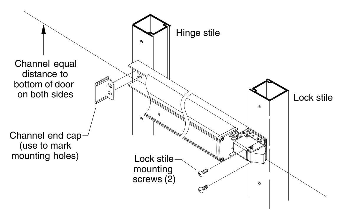
3 Mount device.
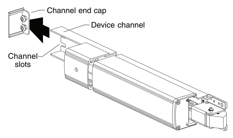
3.1. Start two hinge stile mounting screws (1/4-20 x 1/2" pan head) in channel end cap. Leave screws loose.
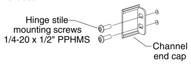
3.2. Slide device channel under channel end cap aligning channel slots.
3.3. If using outside cylinder, align drive bushing assembly over tailpiece maintaining drive bushing position.
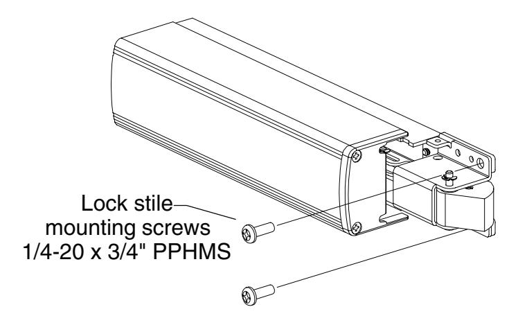
3.4. Attach device to door at lock stile using two lock stile mounting screws (1/4-20 x 3/4" pan head) and tighten securely all four mounting screws.
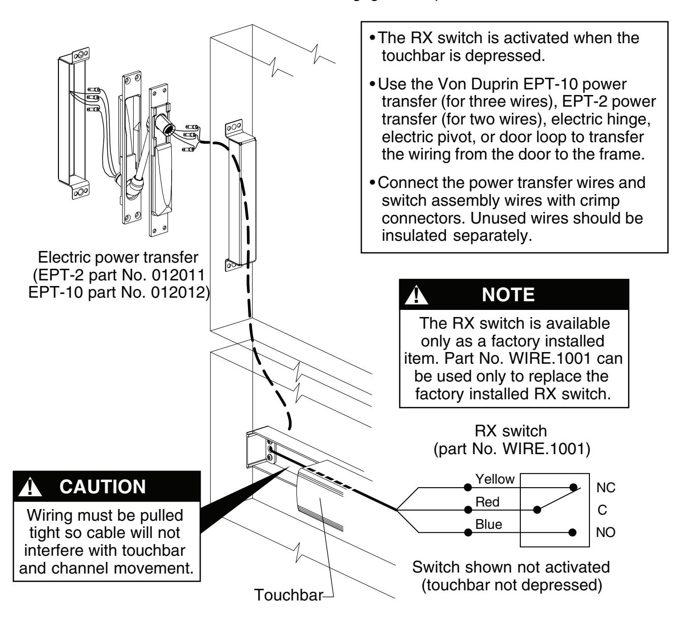
4 Prepare hole and wire EL/RX device. (If device is not EL/RX, go to Step 5.)
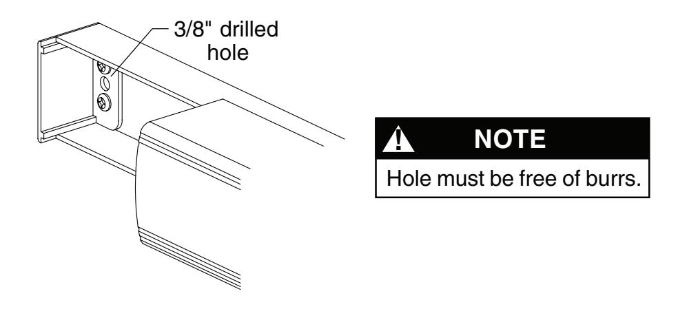
4.1. Drill 3/8" diameter hole for EL/RX wiring through channel end cap, channel, and inside face of door.
4.2. Wire RX switch as shown below. For EL wiring, go to Step 4.3.
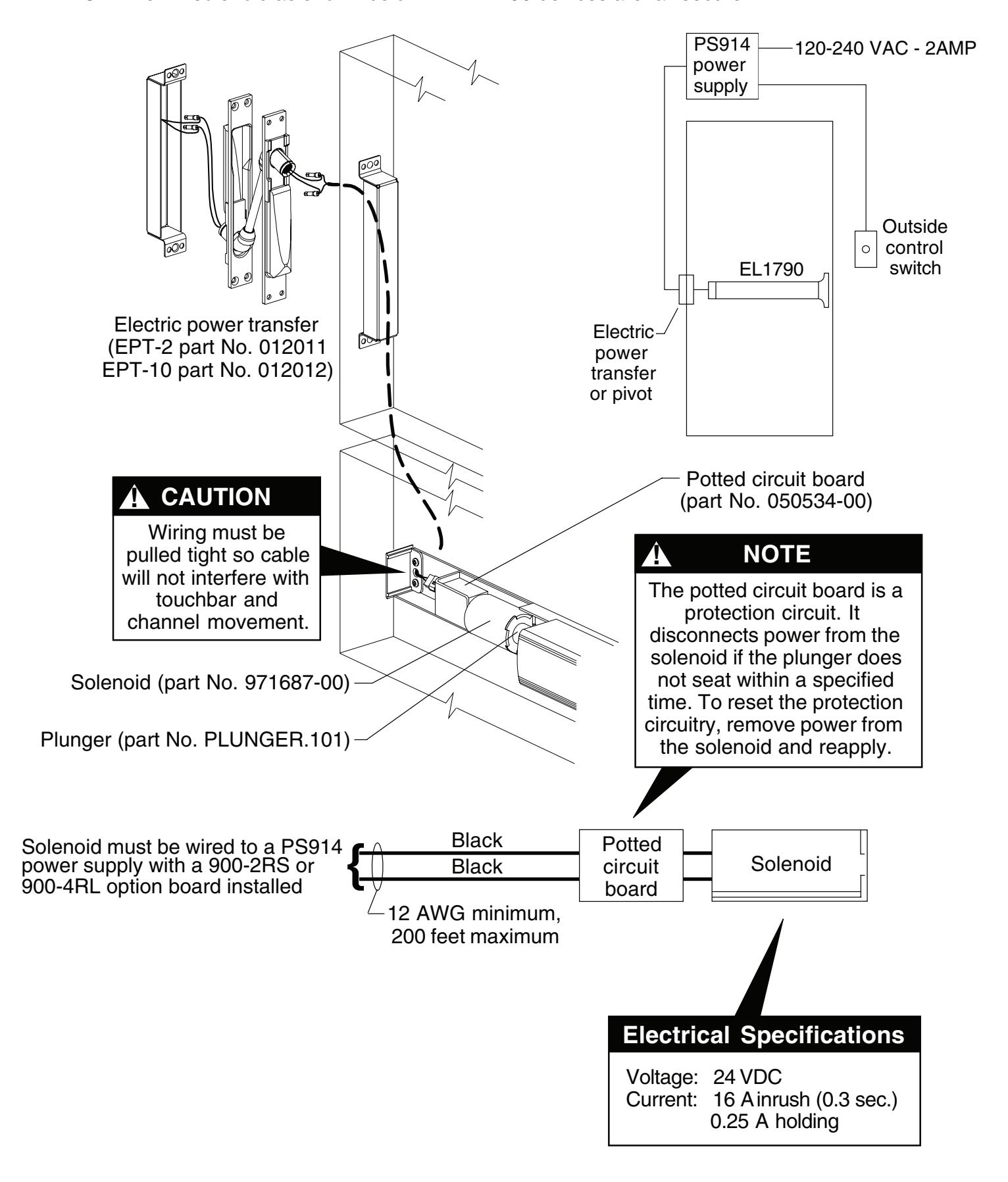
4.3. Wire EL solenoid as shown below, All EL1790 devices are fail secure.
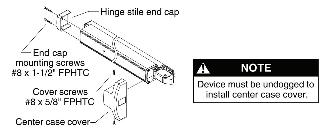
5 Install covers.
- 5.1. Install center case cover with two cover screws (#8 x 5/8" FPHTC).
- 5.2. Install hinge stile end cap with two end cap mounting screws (#8 x 1-1/2" FPHTC).
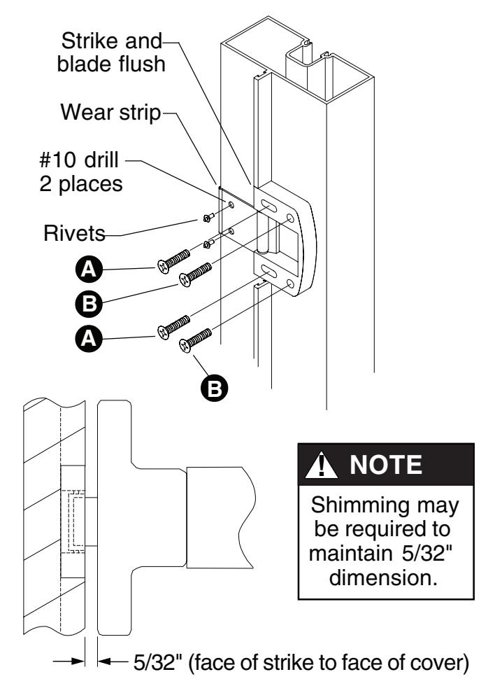
6 Install TD35 strike for non-mullion applications. (See pg. 13 for frame preparation)

- 6.1. Apply strike to frameas shown. Tighten screws marked A so strike is flush with front of blade as shown.
- 6.2. Drill and tap for screws marked B while maintaining alignment of strike and blade stop.
- 6.3. Secure strike.
- 6.4. Place wear strip under front of strike and mark two holes as shown.
- 6.5. Drill through two places with #10 drill for wear strip mounting holes.
- 6.6. Install rivets to wear strip and frame and secure with hammer.
- 6.7. Verify clearance between cover and strike as shown.
7 Perform functional check.
7.1. Dog device. Latch bolt should clear strike roller when door is opened.
TOUCHBAR DOGGING
! NOTE
These instructions are for touchbar dogging of new style DOM 1790 devices. New style devices have two cover screws installed vertically into the center case cover. (Old style devices have four cover screws installed horizontally into the center case cover.)
! NOTE
EL (electric latch retraction) devices cannot be mechanically dogged using the touchbar. If mechanical hold back is required in addition to electric latch hold back, use the pull side HB key cylinder option.
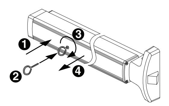
To Dog Device (hold latch retracted)
- 1. Depress touchbar with hand and maintain pressure on touchbar.
- 2. Insert dogging key into hole on touchbar.
- 3. Rotate key approximately 1/8 turn clockwise.
- 4. Release pressure on touchbar (touchbar will remain depressed to door).
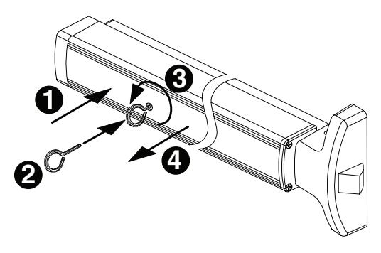
To Undog Device (panic latch locks upon closing)
- 1. Depress touchbar with hand and maintain pressure on touchbar.
- 2. Insert dogging key into hole on touchbar.
- 3. Rotate key approximately 1/8 turn counterclockwise.
- 4. Release pressure on touchbar (touchbar will extend from door).
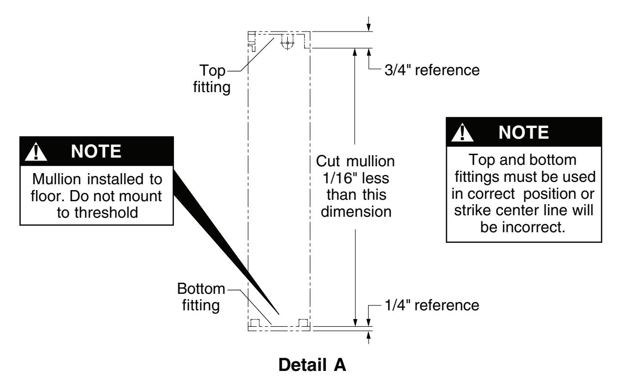
RM170 MULLION INSTALLATION
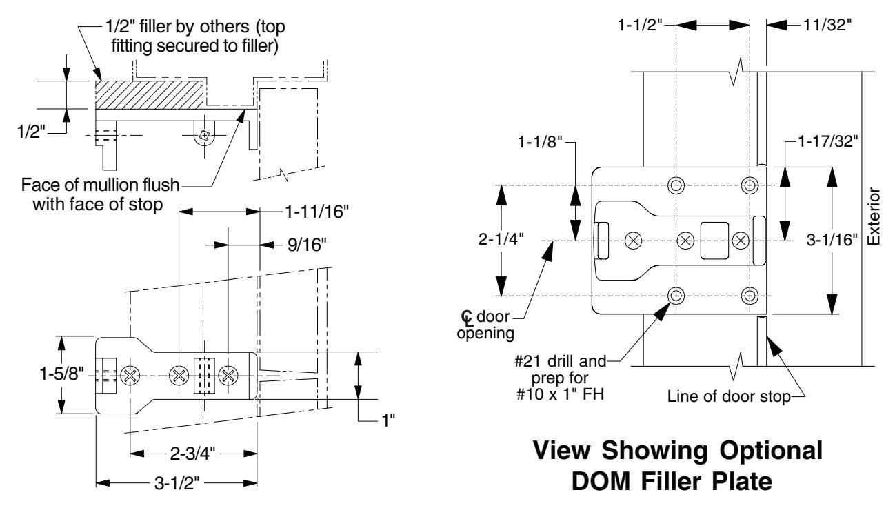
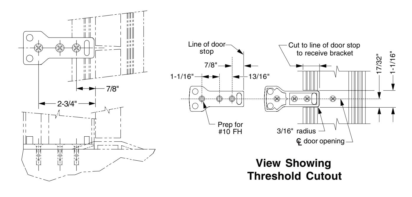
1. Mount top and bottom fittings (see below). To install fittings, line up fittings with center of doorway and flush with doors. Cut out threshold to receive bottom fitting.
Top Fitting
Bottom Fitting
- 2. Measure mullion and cut as required (Detail A). of strike is set at factory to match device template dimension of 42" to finished floor.
- 3. Slide mullion over top fitting and swing into position on bottom fitting (Detail B).
- 4. Slide mullion clamp over top fitting and secure with three screws.
- 5. Locate security clips on door (Detail C). Prepare holes with #21 drill and 10-32 tap and assemble.
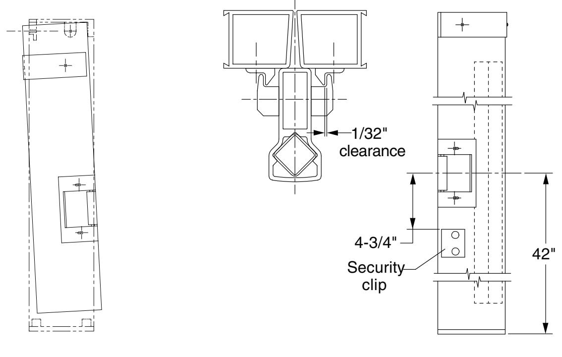
Detail B Detail C
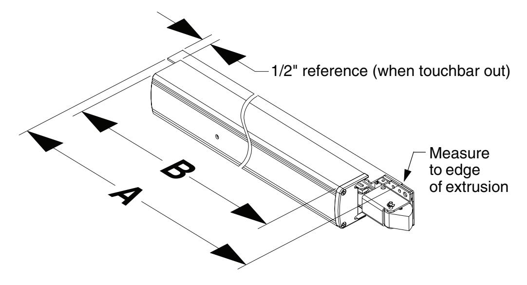
FIELD SIZING DEVICE
Note: These instructions assume a 1/2" blade stop on the door frame.
- 1. Determine door clear opening. This is the distance inside the frame.
- A = door clear opening 2-27/32" 2. Determine channel cut length A :
- 3. Verify that A determined in Step 2 is not less than minimum A dimension listed in table. (Standard 1790 device sizes can be shortened by up to 6" and EL devices can be shortened by up to 1.5"). Cut channel.
|
Standard
Device Size |
Factory
Dimension A |
Standard Device
Minimum Dimension A |
EL Device
Minimum Dimension A |
|---|---|---|---|
|
2'
6" |
27.138" | 21.138" | 25.638" |
|
3'
0" |
33.138" | 27.138" | 31.638" |
|
3'
6" |
39.138" | 33.138" | 37.638" |
|
4'
0" |
45.138" | 39.138" | 43.638" |
4. Determine touchbar cut length B : B = door clear opening 5-7/32"
5. Remove two end cap screws, end cap, and touchbar.
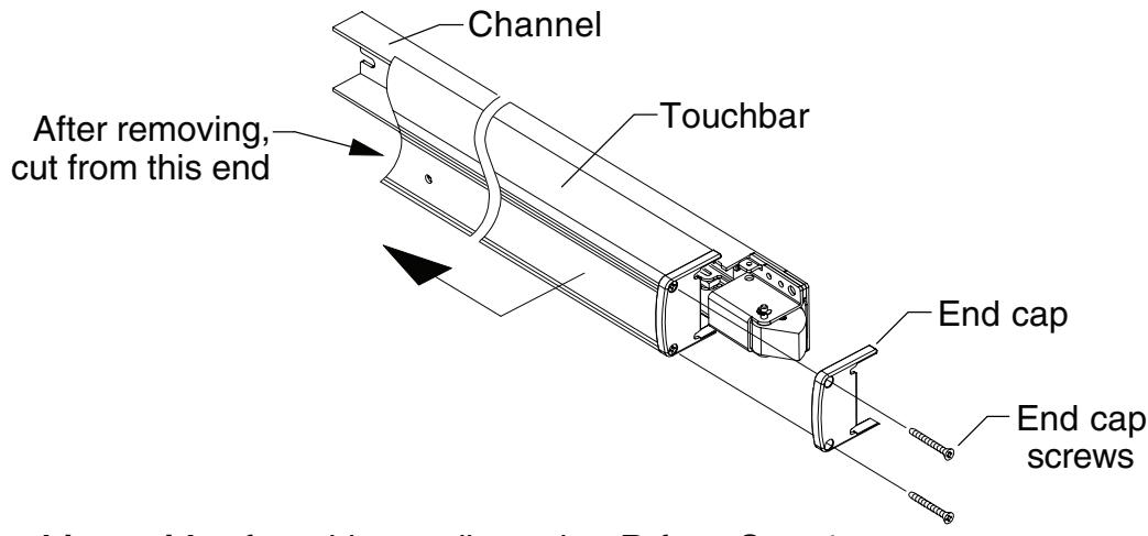
- 6. Cut hinge side of touchbar to dimension B from Step 4.
- 7. Cover device mechanism to keep chips out and cut channel to dimension A from Step 2.
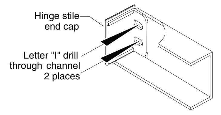
8. If hinge stile has not been prepared for channel hinge stile 1/4-20 mounting screws:
Place hinge stile end cap into hinge end of channel. Drill through the center of end cap slots using a letter "I" drill. These two holes will be used to transfer location of mounting screw holes to hinge stile when device is applied to door.
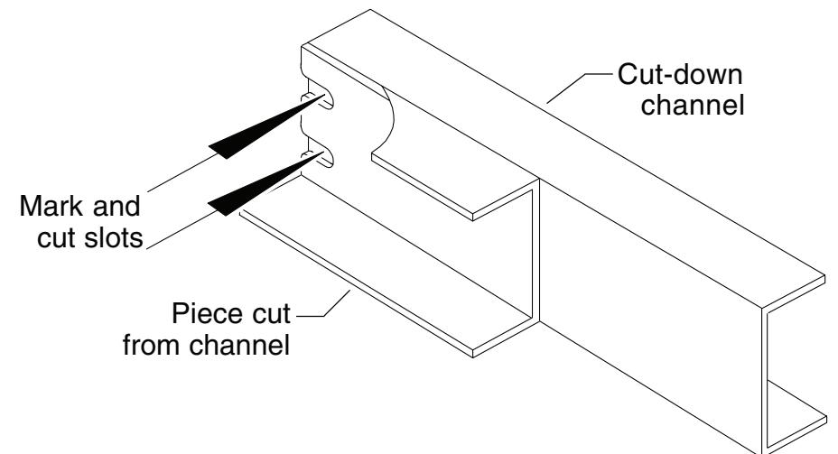
If hinge stile has been prepared for channel hinge stile 1/4-20 mounting screws:
Using end cut from channel in Step 3 as a template, place backs of channel sections against each other and align ends. Mark slot pattern on the cut-down channel. Following all safety precautions, use a drill and aluminum saw to cut slots in cut-down channel section.
- 9. Clean debris from touchbar and channel.
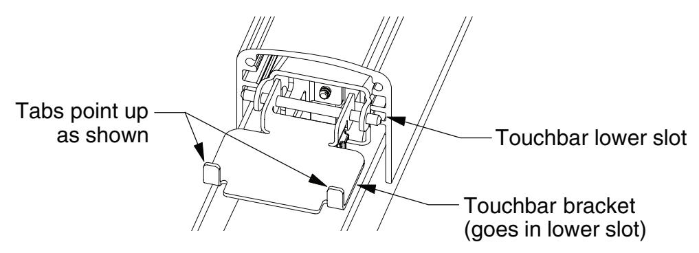
- 10. Slide touchbar over touchbar pins. Make sure to install both pins in lower slot in touchbar. If touchbar bracket is removed, it should be reinstalled with stop tabs turned up away from channel.
11. Reinstall end cap and screws.
2090 RETROFIT INSTRUCTIONS
Note: Retrofitting double doors requires replacement of the RM70 mullion with a RM170 mullion. This is because they have different device center lines.
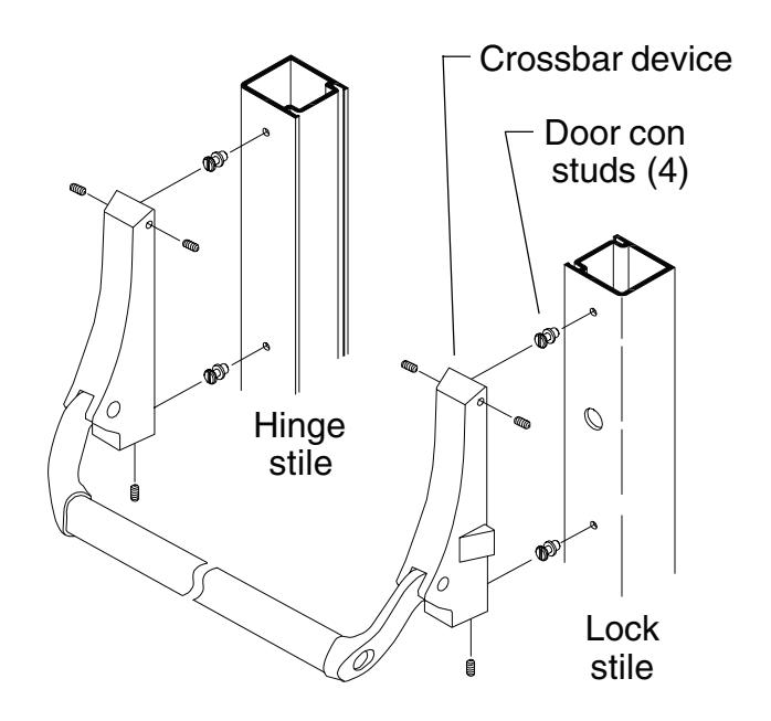
1. Remove crossbar device and door con study from door as shown.
- 2. If door width is non-standard, size device using field sizing directions on page 10.
- 3. Using existing pinion or door con stud hole as a reference, locate the two 1/4-20 mounting holes on the lock stile. Drill and tap 1/4-20, inside face only.
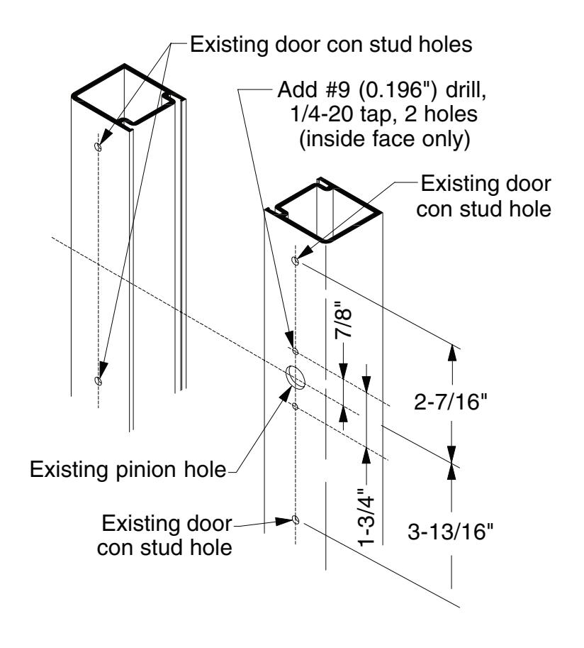
- 4. Mount the device to the lock stile using the supplied 1/4-20 x 3/4" pan head screws.
- 5. Position the device horizontally on the door (same distance from bottom of door to bottom of channel on both stiles).
- 6. Position channel end cap in end of channel and use to mark locations for hinge mounting holes.
- 7. Remove the device from the door.
- 8. Drill and tap through two 1/4-20 mounting holes on hinge stile, inside face only.
- 9. Remove the old 2090 strike and replace with TD35 strike (see Step 6 on page 6).
- 10. Continue on with 1790 installation instructions.
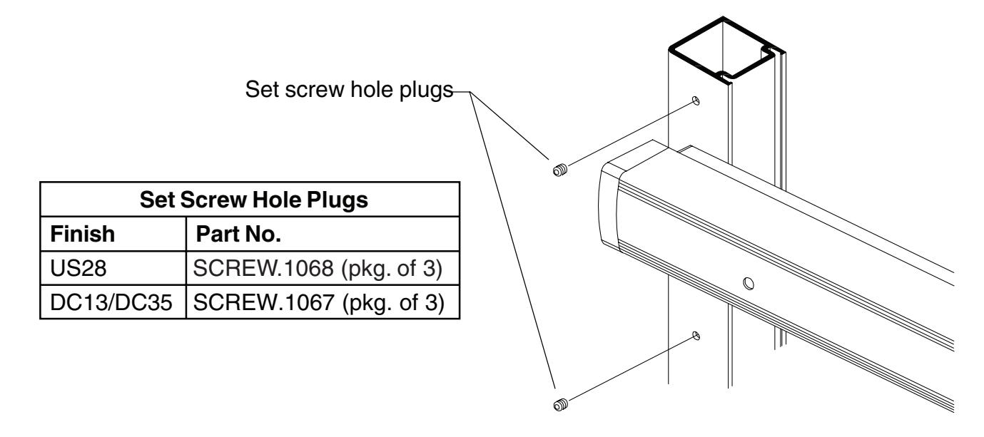
- 11. When installation is complete, install supplied set screw hole plugs in exposed 2090 door con stud holes (two on hinge stile and one on lock stile).
DEVICE TEMPLATE
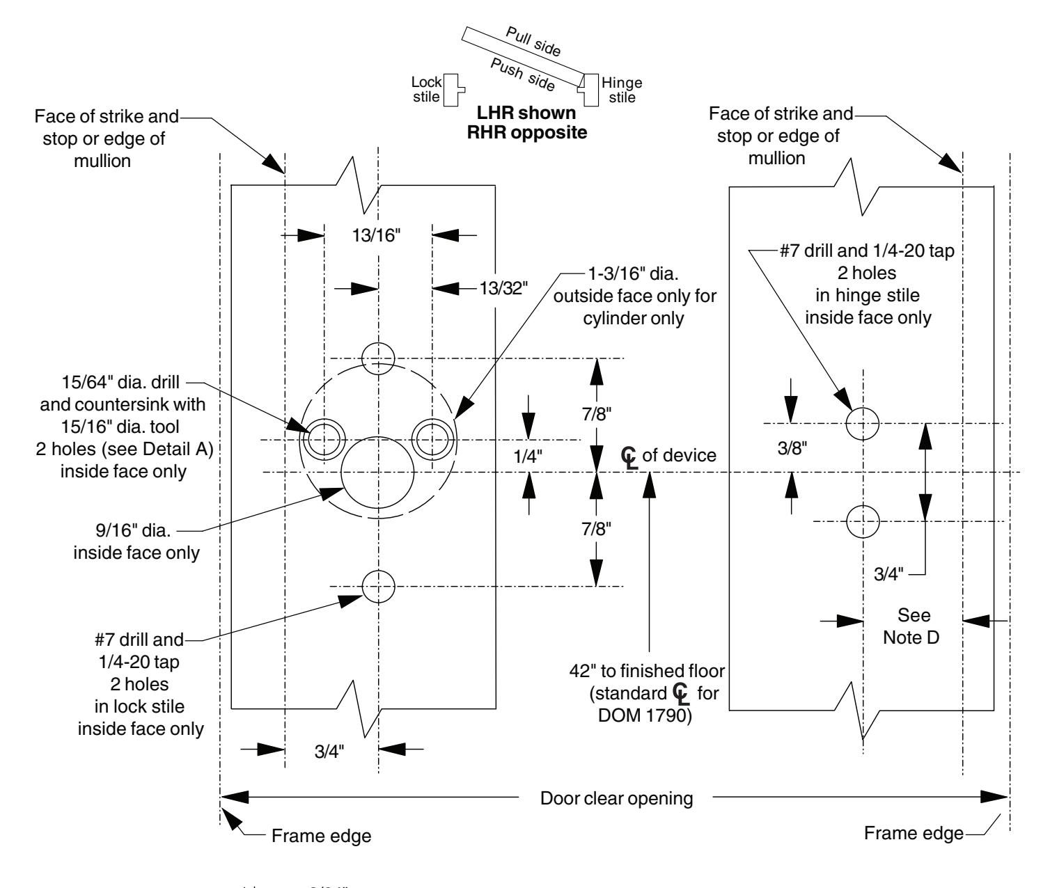
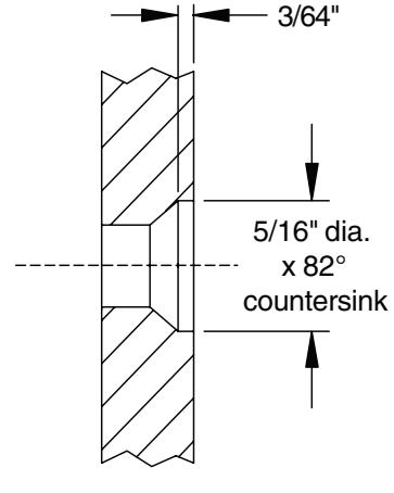
Detail A (for cylinder)
Ţ
NOTES
- 1. All holes inside face only except as noted.
- 2. All dimensions for 1-3/4" thick, 1/8" wall doors. Consult factory for others.
A
NOTE D
Dimensions from face of door blade stop to mounting hole center lines 3/4" minimum.
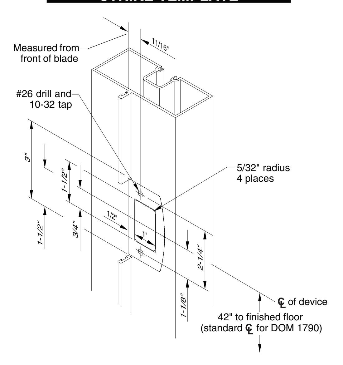
STRIKE TEMPLATE
TOUCHBAR PART NUMBERS
| 30" | 36" | 42" | 48" |
|---|---|---|---|
| Nominal | Nominal | Nominal | Nominal |
| Device | Device | Device | Device |
| Length | Length | Length | Length |
| (24.785" | (30.785" | (36.785" | (42.785" |
| Extrusion | Extrusion | Extrusion | Extrusion |
| Length) | Length) | Length) | Length) |
| Finish |
Without
Dogging Hole |
With
Dogging Hole |
Without
Dogging Hole |
With
Dogging Hole |
Without
Dogging Hole |
With
Dogging Hole |
Without
Dogging Hole |
With
Dogging Hole |
|---|---|---|---|---|---|---|---|---|
| DC13 | EXT.825 | EXT.828 | EXT.399 | EXT.609 | EXT.439 | EXT.736 | EXT.443 | EXT.739 |
| DC35 | EXT.826 | EXT.829 | EXT.400 | EXT.631 | EXT.441 | EXT.737 | EXT.444 | EXT.740 |
| US3 | EXT.2323 | EXT.2351 | EXT.2324 | EXT.2355 | EXT.2341 | EXT.2359 | EXT.2298 | EXT.2363 |
| US10 | EXT.2333 | EXT.2352 | EXT.2334 | EXT.2356 | EXT.2345 | EXT.2360 | EXT.2303 | EXT.2364 |
| US26 | EXT.2338 | EXT.2353 | EXT.2339 | EXT.2357 | EXT.2349 | EXT.2361 | EXT.2304 | EXT.2365 |
| US26D | EXT.2340 | EXT.2354 | EXT.2289 | EXT.2358 | EXT.2350 | EXT.2362 | EXT.2294 | EXT.2366 |
| US28 | EXT.830 | EXT.827 | EXT.398 | EXT.608 | EXT.438 | EXT.646 | EXT.442 | EXT.738 |
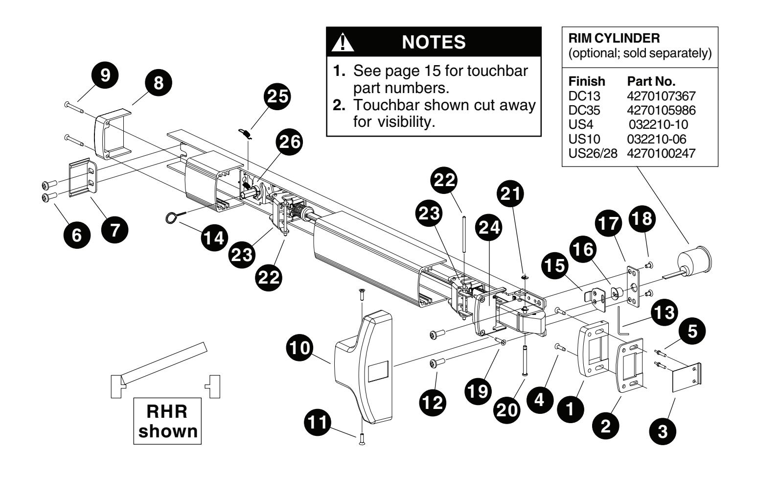
PARTS LIST
|
Package
No. 4270107393 |
|||||
|---|---|---|---|---|---|
| Item | Quantity | Description |
Part
No. |
||
| 1 | 1 | Strike | 4270107227 | ||
| 2 | 1 | Shim | SHIM.150 | ||
| 3 | 1 |
Wear
strip |
4270109590 | ||
| 4 | 2 |
#10
x 1" FPHSMS |
4270104524 | ||
| 5 | 2 |
Drive
rivet |
4299101022 | ||
|
Package
No. ECAP.130 |
|||||
|---|---|---|---|---|---|
| Item | Quantity | Description |
Part
No. |
||
| 6 | 2 |
1/4-20
x 1/2" PPHMS |
4299100074 | ||
| 7 | 1 |
Channel
end cap |
ECAP.127 | ||
| 8 | 1 |
Hinge
stile touchbar end cap |
ECAP.128 | ||
| 9 | 2 |
#8
x 1-1/2" FPHTC |
4270104557 | ||
|
Package
No. COVER.120 |
|||||
|---|---|---|---|---|---|
| Item | Quantity | Description |
Part
No. |
||
| 10 | 1 |
Center
case cover |
COVER.106 | ||
| 11 | 2 |
#8
x 5/8" FPHTC |
SCREW.1056 | ||
|
Package
No. PKG.133 |
|||||
|
Package
No. PKG.133 |
|||||
|---|---|---|---|---|---|
| Item | Quantity | Description |
Part
No. |
||
| 12 | 2 |
1/4-20
x 3/4" PPHMS |
964221-89 | ||
| 13 | 1 |
0.050"
Allen wrench |
4270109548 | ||
| 14 | 1 |
5/32"
hex dogging key |
4270106944 | ||
|
Package
No. 179CA |
||||
|---|---|---|---|---|
| Item | Quantity | Description |
Part
No. |
|
| 15 | 1 | Slider | SLIDER.101 | |
| 16 | 1 |
Drive
bushing |
CAMASY.101 | |
Note: These parts are optional and are required with a rim cylinder. When installed at the factory, these parts are oriented for NL/HB operation. To convert from EO to NL or HB operation, use this kit and a rim cylinder.
| Item | Quantity | Description |
Part
No. |
|---|---|---|---|
| 17 | 1 |
Channel
spacer |
SPACER.107 |
| 18 | 2 |
#10-16
x 3/8" UFPHMS (DC13 or DC35) or |
SCREW.1036 |
| 2 |
#10-16
x 3/8" UFPHMS (US28) |
SCREW.1026 | |
| 19 | 2 |
#8
x 3/4" FPHTF |
4270109556 |
| 20 | 1 |
Latch
bolt pin |
969467-89 |
| 21 | 1 |
Retaining
ring |
964066-89 |
| 22 | 2 |
Touchbar
pin |
PIN.125 |
| 23 | 2 |
Touchbar
anchor |
BRKT.128 |
| 24 | 1 |
Lock
stile touchbar end cap |
ECAP.129 |
| 25 | 1 |
Dogging
spring |
971493-89 |
| 26 | 1 |
Dogging
assembly (DC13 or DC35) or |
KIT.1022 |
|
Dogging
assembly (US28) |
KIT.1021 |