Falcon 1690 Touchbar Concealed Vertical Rod Panic Device Installation Instructions 107989
Open the original PDF document
View PDF

1690 Touchbar
ININST.1002
Concealed Vertical Rod Panic Device
Installation Instructions
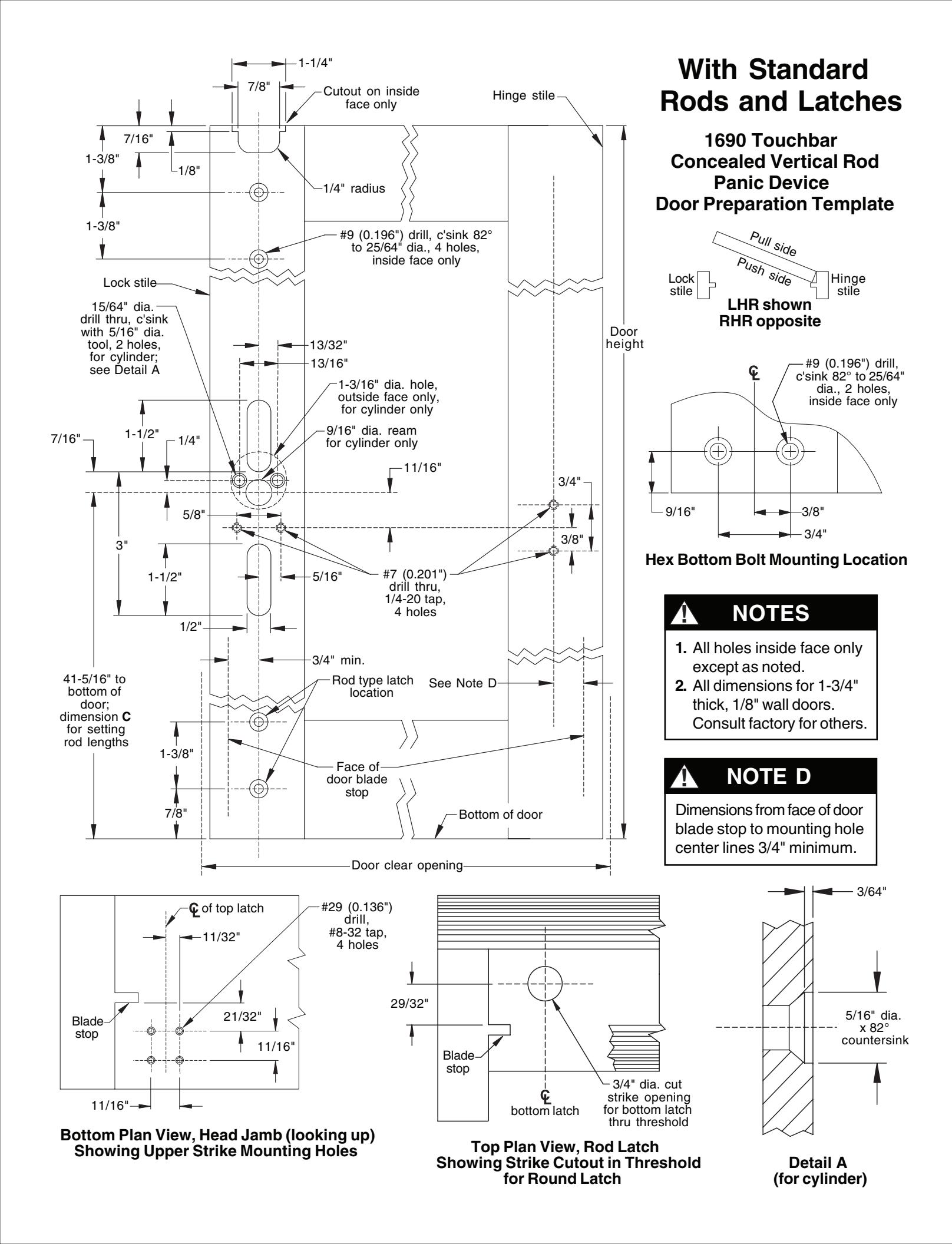
NOTE: The door prep for the 1690 Hex Bottom Rod is different than for the RL bottom rod. Please verify rod type in package and prep required (page 16) before prepping the door.
|
2
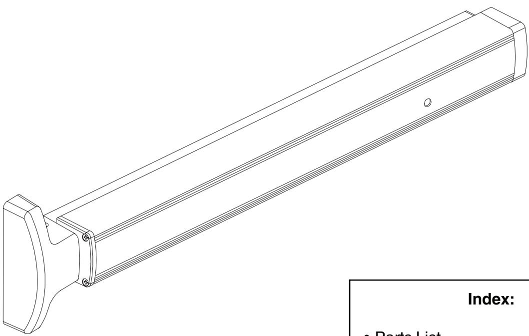
• Parts List |
|
|
•
Touchbar Part Numbers 3 |
|
|
•
Before Installation 3 |
|
|
•
Installation 4 |
|
|
•
Touchbar Dogging 10 |
|
|
•
Setting Rod Lengths 11 |
|
|
•
Re-handing Device 11 |
|
|
•
Field Sizing Device 12 |
|
|
•
1990 Retrofit Instructions 14 |
|
|
•
Template 16 |

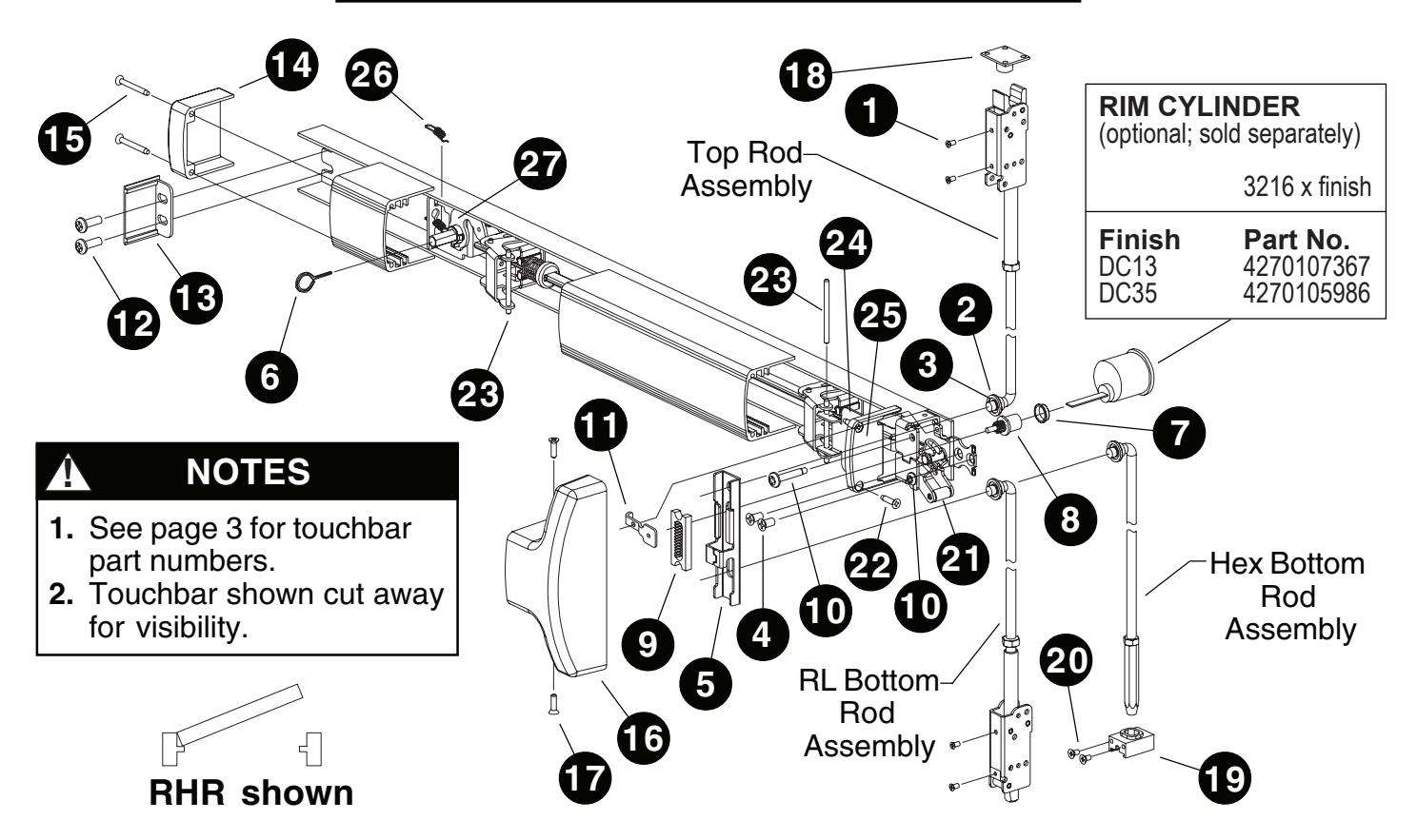
PARTS LIST
| Pack | age N |
No. PKG.150 (US28 finish)
No. PKG.151 (DC13/DC35 f Description |
|
|---|---|---|---|
|
2
3 4 5 6 |
2
4 2 1 1 |
#10-32 x 1/4" UFPHMS US28 finish (Pkg-10) DC13/DC35 finish (Pkg-10) Rod bearing bushing (Pkg-10) Retaining ring (Pkg-25) 1/4-20 x 1/2" FPHMS (Pkg-10) Traveler liftbracket 5/32" hex dogging key (Pkg-10) |
SCREW.1028
SCREW.1029 BUSH.109 RRING.109 SCREW.1069 BRKT.138 KEY.10020 |
| Note | : Öptio | No. 169CA nal. Required with rim cylinder onl Description Cylinder bushing (Pkg-10) Pinion cam Retractor Retainer screw (Pkg-10) Pinion support bracket | y. Part No. BUSH.102 4270903177 RETRACT.101 SCREW.1074 BRKT 478 |
| 11 | ı | Pinion support bracket | DKN 1.470 |
|---|---|---|---|
| Note | : For u | No. 4270902993 se with EO and DT devices only Description Retainer screw (Pkg-10) Pinion support bracket |
Part No.
SCREW.1074 BRKT.478 |
| Package No. ECAP.130 | ||||||||
|---|---|---|---|---|---|---|---|---|
| Item | Description | Part No. | ||||||
| 12 | 2 | 1/4-20 x 1/2" PPHMS (Pkg-10) | SCREW.1070 | |||||
| 13 | 1 | Channel end cap ` ´ ´ ´ | not sold separately | |||||
| 14 | 1 | Hinge stile touchbar end cap | not sold separately | |||||
| 15 | 2 | #8 x̃ 1-1/4" FPHTF (Pkg-10) | SCREW.1072 | |||||
| Package No. COVER.113 | |||||||||
|---|---|---|---|---|---|---|---|---|---|
| Йty | Description | Part No. | |||||||
| 16 | 1 | Center case cover | not sold separately | ||||||
| 17 | 2 | #8 x 5/8" PPHTC Sems (Pkg-10) | SCREW.1025 | ||||||
| Note: | Conta |
Io. PB48
ains strike, three shir |
ns, and four mounting screws. |
|---|---|---|---|
|
Item
18 |
Description
Strike |
Part No. | |
| 10 | ı |
US28 finish
P13 finish P35 finish |
4270108353
4270108354 4270108355 |
| Package No. 4270107176 (US28 finish) or Package No. 4270107178 (DC13/DC35 finish) | ||||||||
|---|---|---|---|---|---|---|---|---|
| Qty | Description | Part No. | ||||||
| 19 | 1 | Hex rod guide | not sold separately | |||||
| 20 | 2 | #10-24 x 3/8" UFPHTC Typ F Stl | ||||||
| US28 finish | not sold separately | |||||||
| DC13/DC35 finish | not sold separately | |||||||
| Item | Qty | Description | Part No. |
|---|---|---|---|
| 21 | 1 | Lift arm | BRKTASY.107 |
| 22 | 2 | #8 x 3/4" FPHTF (Pkg-10) | SCREW.1077 |
| 23 | 2 | Touchbar pin (Pkg-10) ´ | PIN.128 |
| 24 | 2 | Touchbar anchor / | BRKT.128 |
| 25 | 1 | Lock stile touchbar end cap | ECAP.129 |
| 26 | 1 | Dogging spring | 971493-76 |
| 27 | 1 | Dogging spring Dogging assembly | KIT.1197 |
PARTS LIST (CONTINUED)
TOUCHBAR PART NUMBERS
|
30"
Nominal (24.785" |
Device
Length Extrusion Length) |
36"
Nominal (30.785" |
Device
Length 42" Extrusion Length) |
Device
Length Extrusion Length) |
48"
Nominal Device Length (42.785" Extrusion Length) |
||||
|---|---|---|---|---|---|---|---|---|---|
| Finish |
Without
Dogging Hole |
With
Dogging Hole |
Without
Dogging Hole |
With
Dogging Hole |
Without
Dogging Hole |
With
Dogging Hole |
Without
Dogging Hole |
With
Dogging Hole |
|
| DC13 | EXT.825 | EXT.828 | EXT.399 | EXT.609 | EXT.439 | EXT.736 | EXT.443 | EXT.739 | |
| DC35 | EXT.826 | EXT.829 | EXT.400 | EXT.631 | EXT.441 | EXT.737 | EXT.444 | EXT.740 | |
| US3 | EXT.2323 | EXT.2351 | EXT.2324 | EXT.2355 | EXT.2341 | EXT.2359 | EXT.2298 | EXT.2363 | |
| US10 | EXT.2333 | EXT.2352 | EXT.2334 | EXT.2356 | EXT.2345 | EXT.2360 | EXT.2303 | EXT.2364 | |
| US26 | EXT.2338 | EXT.2353 | EXT.2339 | EXT.2357 | EXT.2349 | EXT.2361 | EXT.2304 | EXT.2365 | |
| US26D | EXT.2340 | EXT.2354 | EXT.2289 | EXT.2358 | EXT.2350 | EXT.2362 | EXT.2294 | EXT.2366 | |
| US28 | EXT.830 | EXT.827 | EXT.398 | EXT.608 | EXT.438 | EXT.646 | EXT.442 | EXT.738 | |
BEFORE INSTALLATION
- 1. Check "Parts List" (see page 2).
- 2. Prepare door using template on page 16.
- 3. Set initial rod lengths (see page 11). Rods are factory set for standard 7' door.
- 4. If door width is non-standard, cut device (see page 12).
- 5. If necessary, re-hand device (see page 11).
INSTALLATION
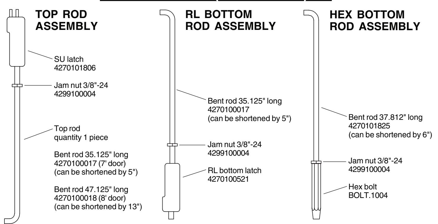
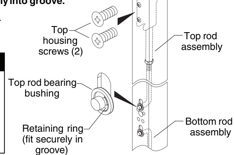
1 Install rod assemblies.
1.1. Install top rod assembly into door. Secure with #10-32 x 1/4" housing screws, retaining ring, and rod bearing bushing. Make sure retaining ring fits securely into groove.
1.2. Install bottom rod assembly into door same as top rod assembly.
! NOTE
For hex bottom rod, hex guide mounting holes are horizontal. Use two #10-24 x 3/8" mounting screws provided in hex mounting package to mount hex guide. Discard two extra #10-32 x 1/4" mounting screws in device mounting package.
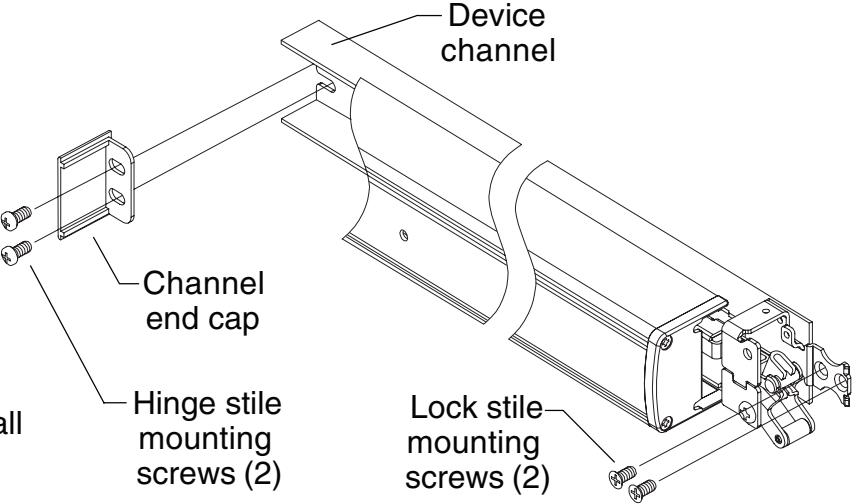
2 Mount device.
- 2.1. Start two 1/4-20 x 1/2" pan head hinge stile mounting screws in channel end cap. Leave screws loose.
- 2.2. Slide device channel under channel end cap aligning channel slots.
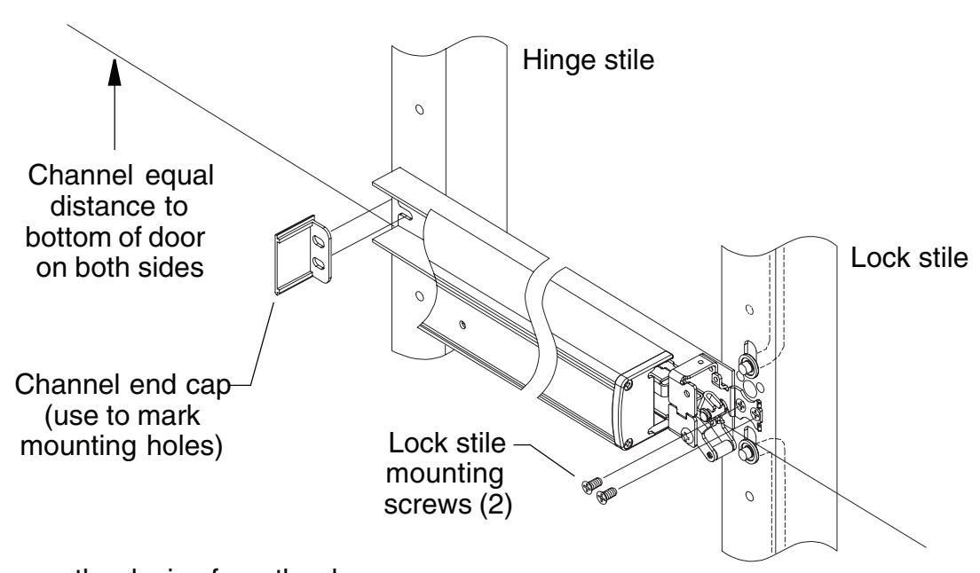
- 2.3. Attach lock stile of device to door using two 1/4-20 x 1/2" flat head lock stile mounting screws and tighten securely all four mounting screws.
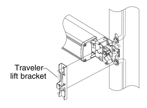
3 Install traveler lift bracket over rod ends as shown.
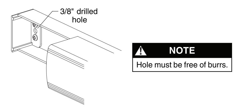
4 Prepare hole and wire EL/RX device. (If device is not EL/RX, go to Step 5.)
4.1. Drill 3/8" diameter hole for EL/RX wiring through channel end cap, channel, and inside face of door.
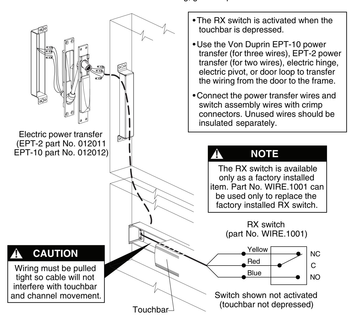
4.2. Wire RX switch as shown below. For EL wiring, go to Step 4.3.
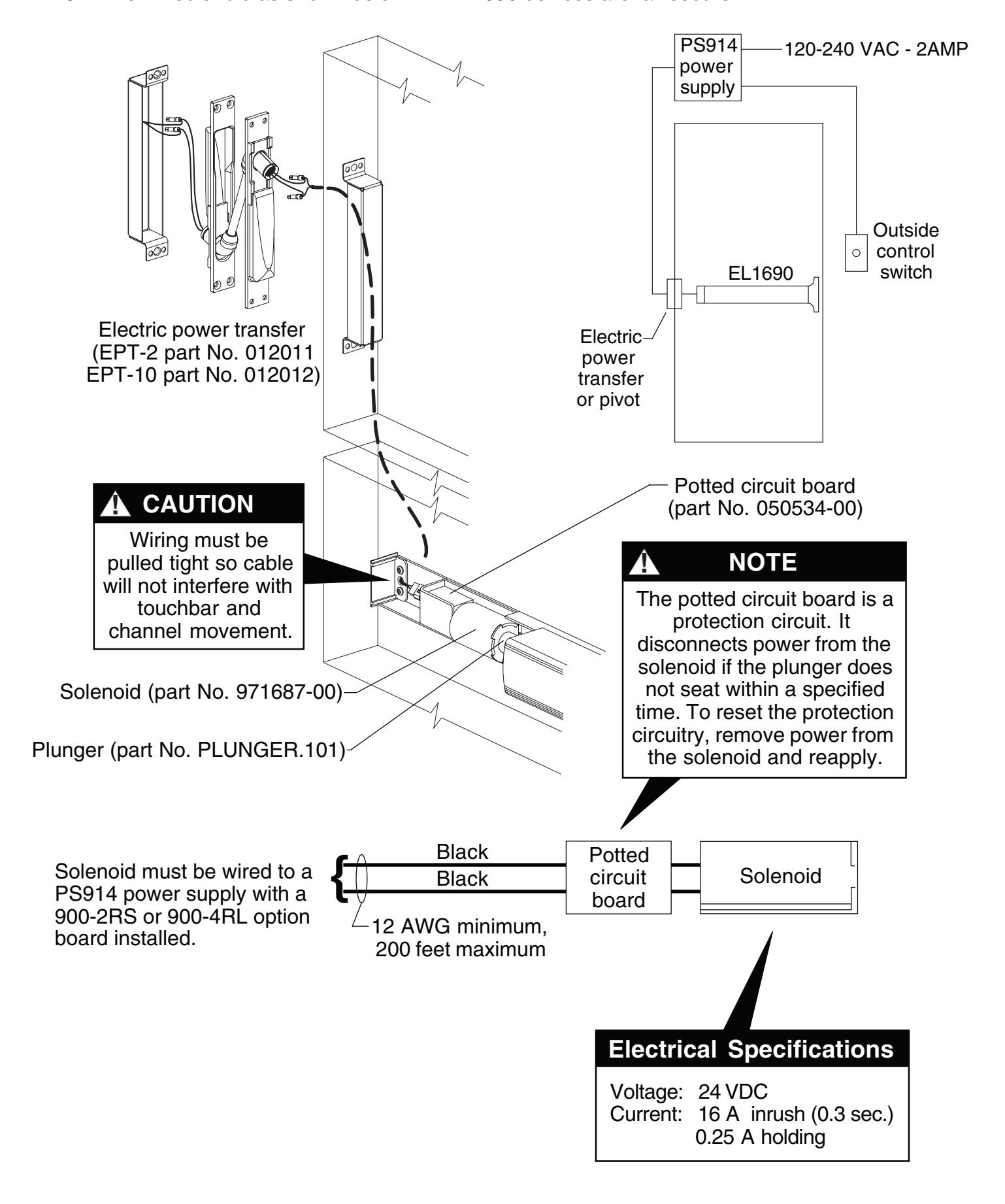
4.3. Wire EL solenoid as shown below. All EL1690 devices are fail secure.
Top Rod Adjustment
-
5.1.
Dog the device. If it dogs and undogs freely, go to Step 5.2. If it does not, the top rod is too long. To determine how much to shorten the top rod:
- A. Undog the device.
- B. Hold the top rod all the way up and push the lift arm to the bottom of its travel with the touchbar completely out.
- C. Measure the distance between the bottom of the traveler projection and the top of the lift arm roller (see Figure 5-1).
- D. Subtract the distance from 1/2".
- E. Using the difference from Step D, find the number of turns to shorten the top rod from the "Rod Adjustment Table" below.
- F. Remove the top rod and shorten it by the required number of turns. Reinstall the top rod.
-
5.2.
Dog the device and push the traveler against the lift arm while maintaining pressure on the traveler. Attempt to pivot the top latch bolt (See Figure 5-2). If the top latch bolt pivots freely, go to Step 5.3. If the top latch bolt drags or lifts the top rod, the top rod is too short. To determine how much to lengthen the top rod:
- A. Push the traveler all the way down then slowly lift it away from the lift arm until the top latch bolt moves freely.
- B. Measure the distance between the bottom of the traveler projection and the top of the lift arm roller (see Figure 5-1).
- C. Using the measured distance, find the number of turns to lengthen the top rod from the "Rod Adjustment Table" below.
- D. Remove the top rod and lengthen it by the required number of turns. Reinstall the top rod.
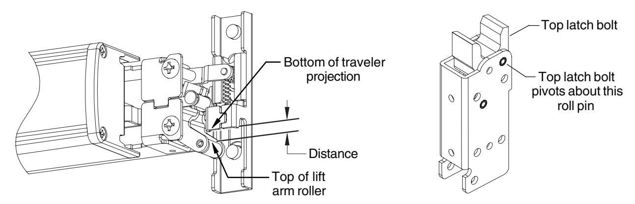
Figure 5-1
Figure 5-2
|
Rod
AdjustmentTable |
||||||||||||||||
|---|---|---|---|---|---|---|---|---|---|---|---|---|---|---|---|---|
| Distance | 1/32" | 1/16" | 3/32" | 1/8" | 5/32" | 3/16" | 7/32" | 1/4" | 9/32" | 5/16" | 11/32" | 3/8" | 13/32" | 7/16" | 15/32" | 1/2" |
| No. of Turns | 1 | 2 | 3 | 3 | 4 | 5 | 6 | 6 | 7 | 8 | 9 | 9 | 10 | 11 | 12 | 12 |
Bottom Rod Adjustment
- 5.3. Undog the device and push down firmly on the lift arm and on the end of the bottom rod (be sure the touchbar is all the way out). Find the distance of the bottom rod from the bottom of the door. Make sure you measure from the bottom of the door, not from the latch housing. If the bottom rod is flush with the door or sticks out from the door no more than 1/32" go to Step . 7
-
5.4.
If the bottom rod sticks out more than 1/32" the bottom rod is too long. To determine how much to shorten the bottom rod:
- A. Measure the distance that the bottom rod sticks out of the door and look up the number of turns required to shorten the bottom rod in the "Rod Adjustment Table."
- B. Remove the bottom rod, shorten it by the required number of turns, and reinstall the bottom rod.
-
5.5.
If the bottom rod is recessed into the door by more than 1/16" the bottom rod is too short. To determine how much to lengthen the bottom rod:
- A. Measure the distance that the bottom rod is recessed into the door and look up the number of turns required to lengthen the bottom rod in the "Rod Adjustment Table."
- B. Remove the bottom rod, lengthen it by the required number of turns, and reinstall bottom rod.
6 Install outside cylinder. (If no outside cylinder, go to Step 8.)
- 6.1. Remove traveler lift bracket and axle (Figure 6-1).
- 6.2. Cut cylinder tailpiece to correct length (Figure 6-2).
- 6.3. Install cylinder into door and secure with two mounting screws. Screws must be flush with surface of door.

The lift arm should remain attached to the device. Removing the axle simplifies Step 6.2.
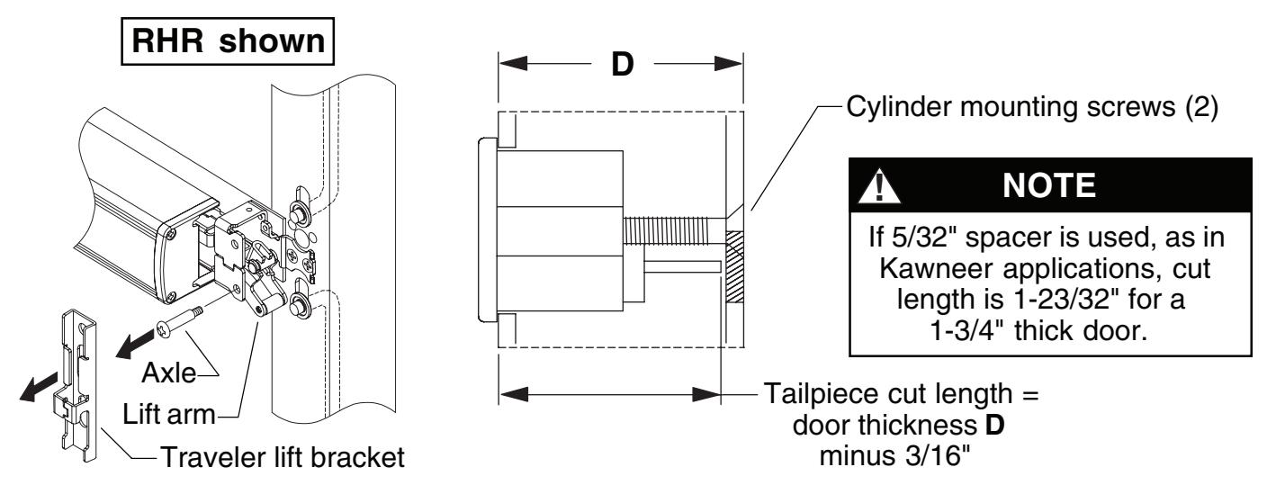
Figure 6-2 Figure 6-1
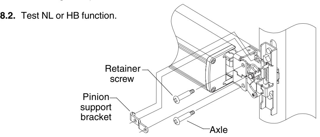
7 Install pinion cam, retractor, and traveler lift bracket (for outside cylinder only).
- 7.1. With cylinder in locked position and key removed, install cylinder bushing and pinion cam into hole (Figure 7-1). Orient pinion cam as shown.
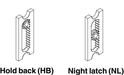
- 7.2. Install retractor into traveler under tabs and place over rods (Figure 7-2). Position retractor as shown for NL or HB function (Figure 7-3).
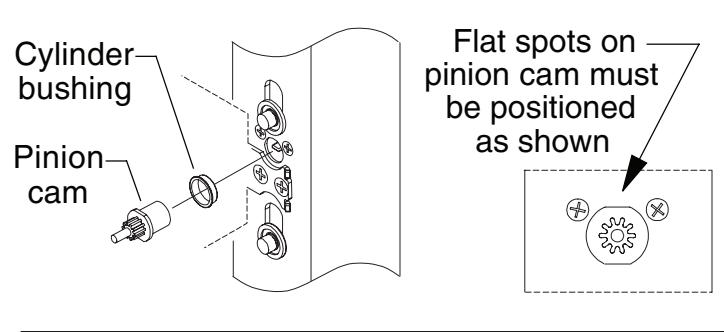

Apply a light coating of Duralub or equivalent lubricant to prolong life of pinion cam.
Figure 7-1
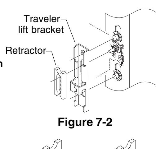
Install retractor with teeth to right as shown for both RHR and LHR doors; this makes all keys function in the same direction
Figure 7-3
8 Install pinion gear support bracket, retainer screw, and axle.
8.1. Install pinion gear retainer, retainer screw, and axle. (Retainer screw and axle are interchangeable.)
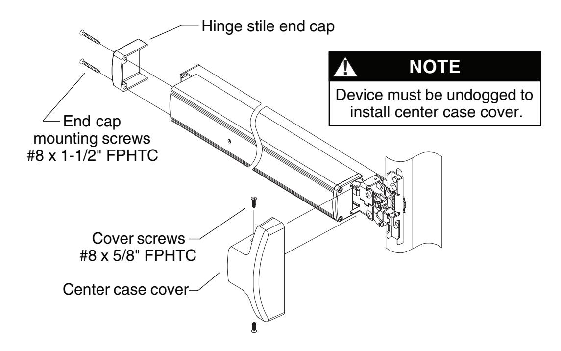
9 Install covers.
- 9.1. Install center case cover over center case and tighten securely with two (#8 x 5/8" FPHTC) cover screws.
- 9.2. Place hinge stile end cap over pushbar and secure with two (#8 x 1-1/2" FPHTC) end cap mounting screws.
10 Perform functional check.
- 10.1. Press touchbar and release so top latch locks forward. Bottom latch bolt should be flush to within 1/32" to bottom of door.
- 10.2. Dog device. Top latch should pivot freely.
TOUCHBAR DOGGING
! NOTE
These instructions are for touchbar dogging of new style DOM 1690 devices. New style devices have two cover screws installed vertically into the center case cover. (Old style devices have four cover screws installed horizontally into the center case cover.)
! NOTE
EL (electric latch retraction) devices cannot be mechanically dogged using the touchbar. If mechanical hold back is required in addition to electric latch hold back, use the pull side HB key cylinder option.
To Dog Device (hold latch retracted)
- 1. Depress touchbar with hand and maintain pressure on touchbar.
- 2. Insert dogging key into hole on touchbar.
- 3. Rotate key approximately 1/8 turn clockwise.
- 4. Release pressure on touchbar (touchbar will remain depressed to door).
To Undog Device (panic latch locks upon closing)
- 1. Depress touchbar with hand and maintain pressure on touchbar.
- 2. Insert dogging key into hole on touchbar.
- 3. Rotate key approximately 1/8 turn counterclockwise.
- 4. Release pressure on touchbar (touchbar will extend from door).
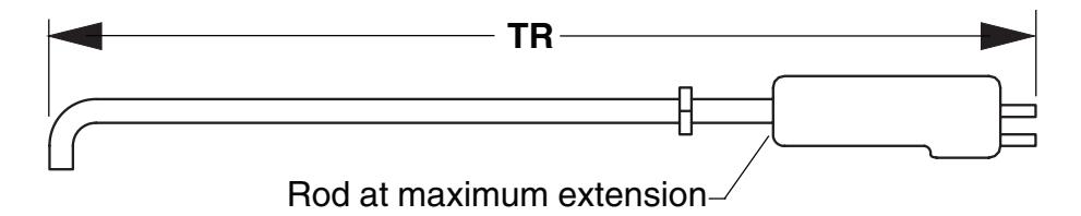
SETTING ROD LENGTHS
! NOTE
Factory length settings are for standard 7' door (door height = 83.187") with C dimension = 41.313": TR = 41-7/32" (41.219") and BR = 39-25/32" (39.781")
1. Determine top rod set length TR: TR = door height C 0.655"
where C = distance from center line of pinion to bottom of door (template standard is 41-5/16").
- 2. Set top rod to nearest 1/32" as determined in Step 1. Jamb nut must be tightened so bent end of rod is parallel to sides of latch housing.
- 3. Determine overall bottom rod length BR: BR = C 1.532"
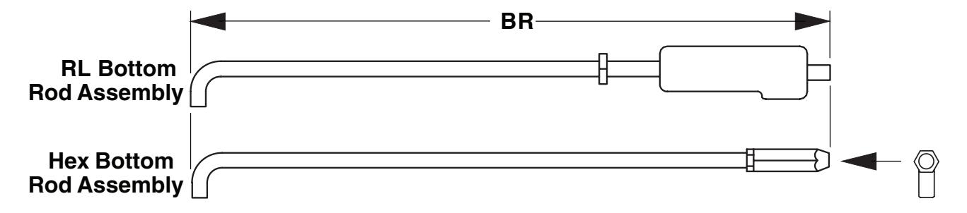
4. Set bottom rod to nearest 1/32" as determined in Step 3. For RL bottom rod assembly, jamb nut must be tightened so bent end of rod is parallel to sides of latch housing. For hex bottom rod assembly, jamb nut must be tightened so bent end of rod is perpendicular to flat on hex bolt (see end view).
End View Rod end must be parallel toflat on hex bolt
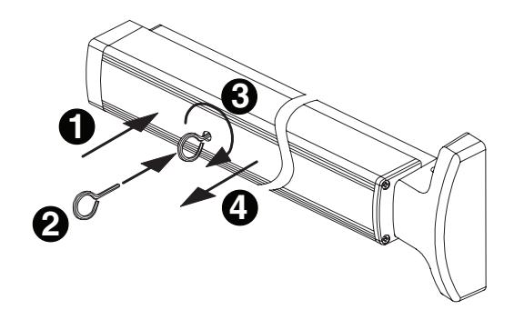
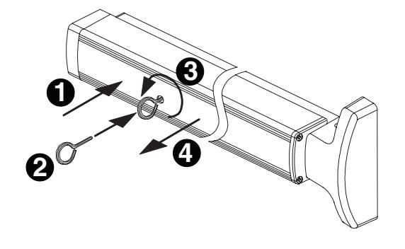
RE-HANDING DEVICE
- 1. Remove axle (Figure 1).
- 2. Remove lift arm and reinstall on opposite side (Figure 2).
- 3. Reinstall axle and tighten securely (Figure 3).
- 4. Verify that lift arm moves smoothly when touchbar is depressed. Figure 1 Figure 2
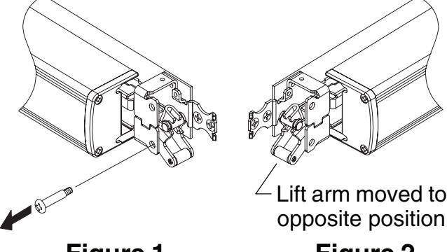
Figure 3
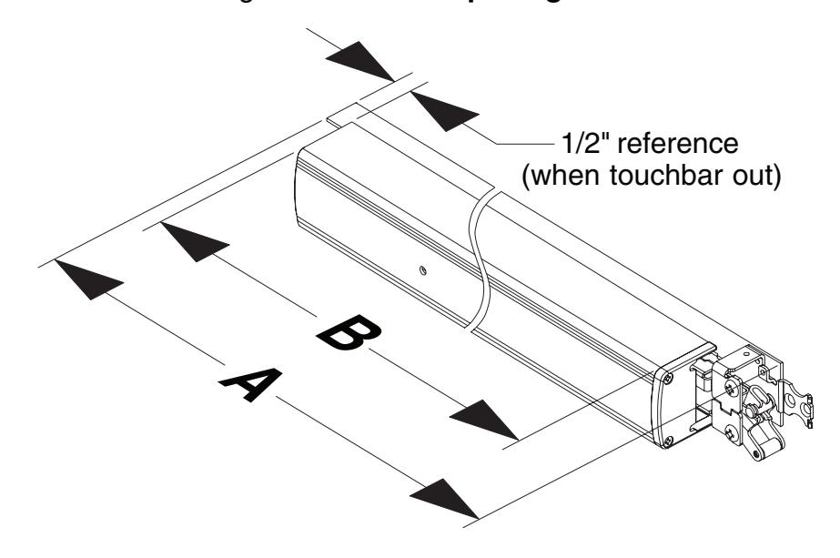
FIELD SIZING DEVICE
Note: These instructions assume a 1/2" blade stop on the door frame.
- 1. Determine door clear opening. This is the distance inside the frame.
- 2. Determine channel cut length A : A = door opening 2-27/32"
- 3. Verify that A determined in Step 2 is not less than minimum A dimension listed in table. Standard 1690 devices can be shortened by up to 6". EL devices can be shortened by up to 1.5".
|
Standard
Device Size |
Factory
Dimension A |
Standard
Device Minimum Dimension A |
EL Device
Minimum Dimension A |
|---|---|---|---|
|
2'
6" |
27.138" | 21.138" | 25.638" |
|
3'
0" |
33.138" | 27.138" | 31.638" |
|
3'
6" |
39.138" | 33.138" | 37.638" |
|
4'
0" |
45.138" | 39.138" | 43.638" |
4. Determine touchbar cut length B : B = door opening 5-7/32"
5. Remove two end cap screws, end cap, and touchbar.
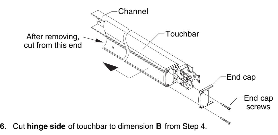
7. Cover device mechanism to keep chips out and cut channel to dimension A from Step 2.
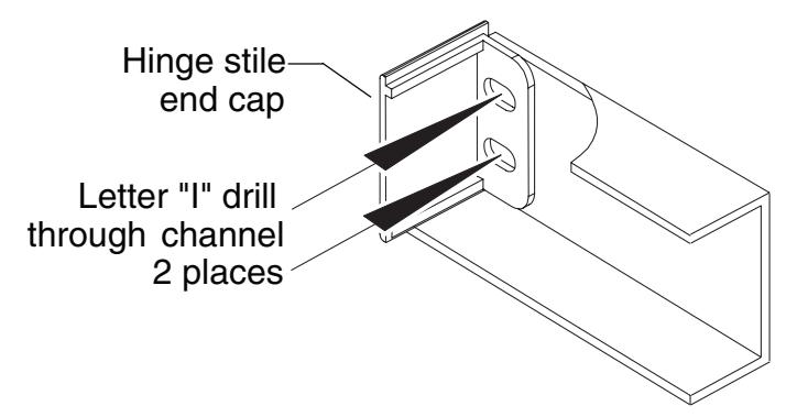
8. If hinge stile has not been prepared for channel hinge stile 1/4-20 mounting screws:
Place hinge stile end cap into hinge end of channel. Drill through the center of end cap slots using a letter "I" drill. These two holes will be used to transfer location of mounting screw holes to hinge stile when device is applied to door.
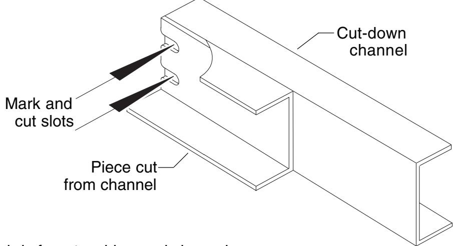
If hinge stile has been prepared for channel hinge stile 1/4-20 mounting screws:
Using end cut from channel in Step 3 as a template, place backs of channel sections against each other and align ends. Mark slot pattern on the cut-down channel. Following all safety precautions, use a drill and aluminum saw to cut slots in cut-down channel section.
- 9. Clean debris from touchbar and channel.
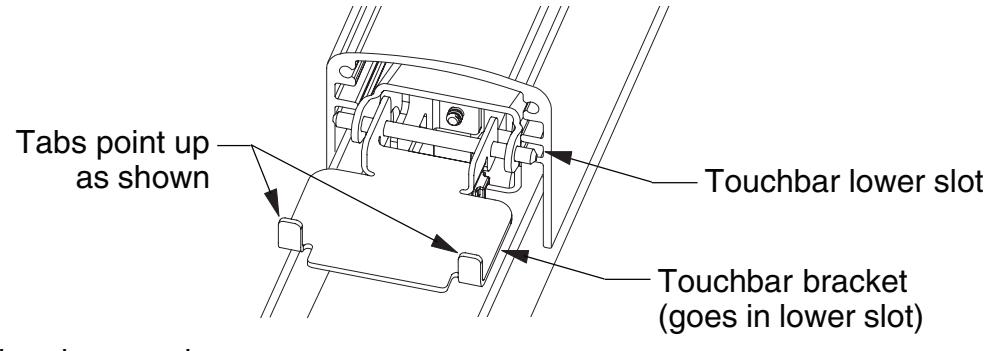
- 10. Slide pushbar over touchbar pins. Make sure to install both pins in lower slot in pushbar. If touchbar bracket is removed, it should be reinstalled with stop tabs turned up away from channel.
11. Reinstall end cap and screws.
1990 RETROFIT INSTRUCTIONS
1. Remove crossbar device, door con studs, traveler, retractor, pinion, pinion bushing, rod bushings and rings from door.
Note: Pinion, pinion bushing, and retractor present on NL/HB devices only.
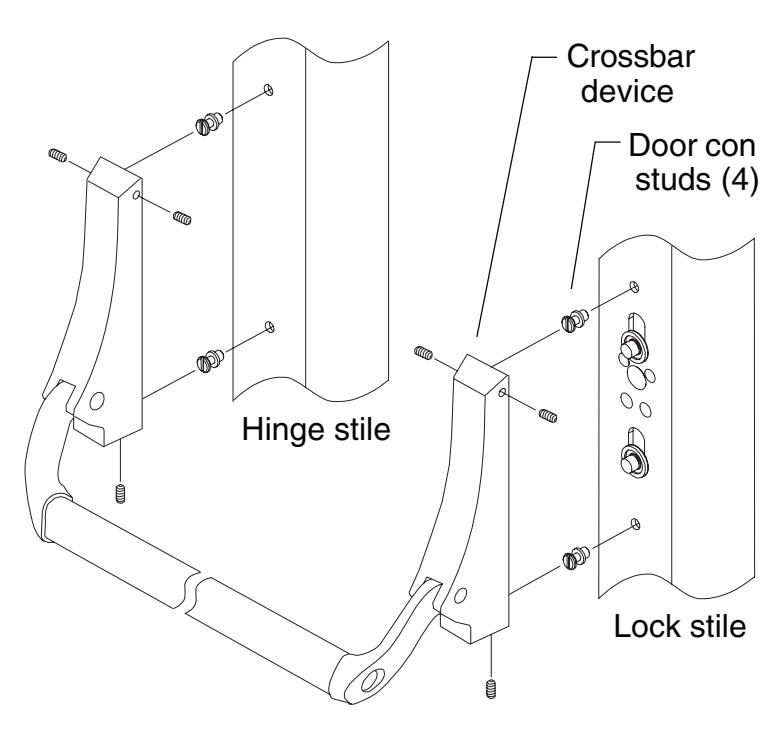
- 2. If non-standard door width, follow field sizing directions on page 12 to size device to appropriate length.
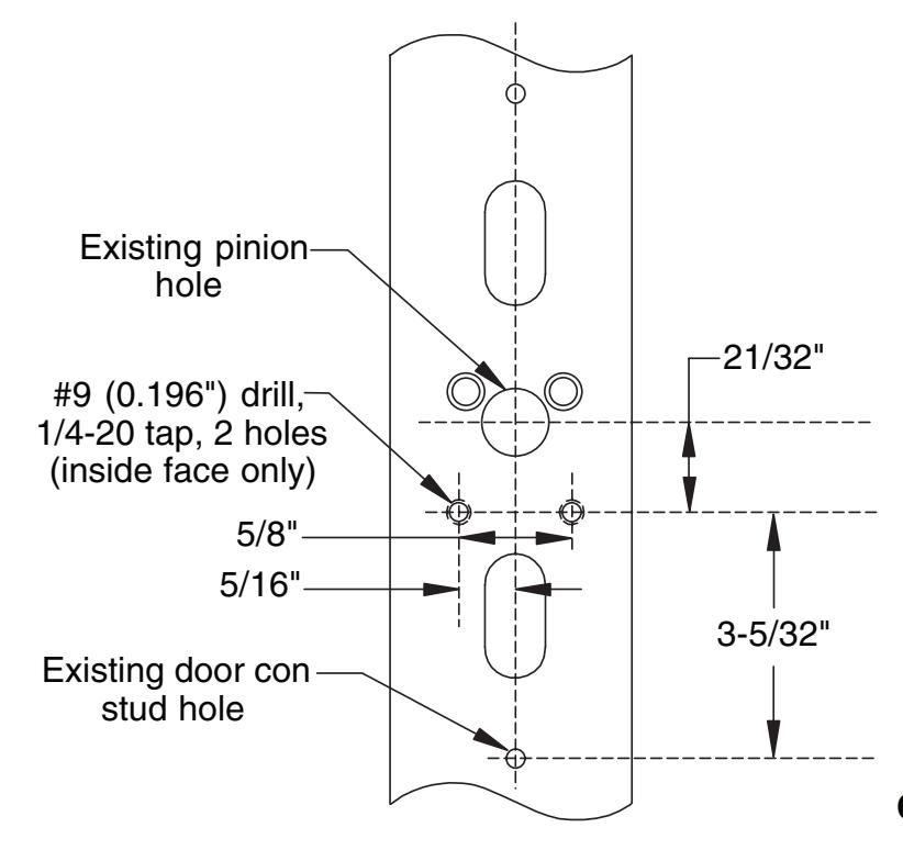
- 3. Using existing pinion or door con stud holes as a reference, locate the two 1/4-20 mounting holes on the lock stile. Drill and tap 1/4-20, inside face only.
Continued on next page
- 4. Install new rod bushings and retaining rings (refer to Step 1 on page 4 of instructions).
- 5. Mount the device to the lock stile using the supplied 1/4-20 undercut flat head screws.
- 6. Position the device horizontally on the door (same distance from bottom of door to bottom of channel on both stiles).
- 7. Position channel end cap in end of channel and use to mark locations for hinge mounting holes.
- 8. Remove the device from the door.
- 9. Drill and tap through two 1/4-20 mounting holes on hinge stile, inside face only.
- 10. Continue on with 1690 installation instructions.
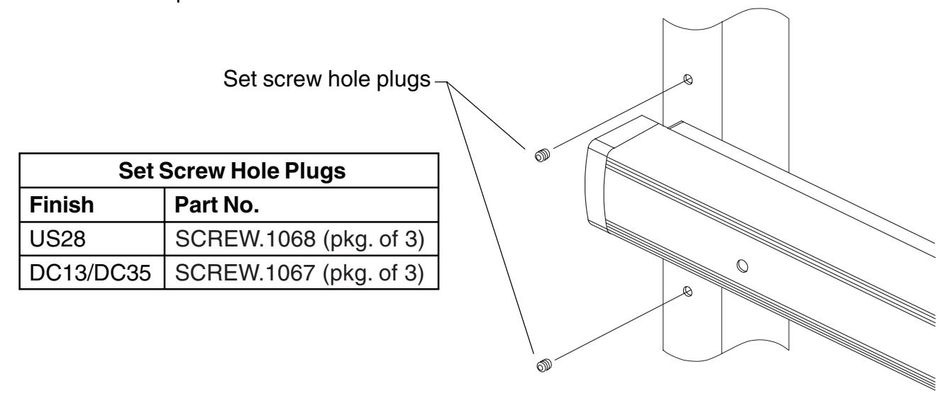
- 11. When installation is complete, remove the 1/4-20 set screws from the old 1990 end cases and install them in the exposed 1990 door con stud holes on the hinge stile. The lock stile holes do not need to be filled. If the set screws in the 1990 end cases are unavailable or unusable, new set screws can be ordered as listed in the table below. New set screw hole plugs are factory supplied if retrofit is specified on the device order.