Falcon 1590 Touchbar Rim Exit Device Installation Instructions 108145
Open the original PDF document
View PDFFALCON <sub>®</sub> Installation Instructions
1590 Touchbar Rim Exit Device
Applies to EL and standard 1590, 1591, 1592, 1593, 1594, 1595
Prepare door.
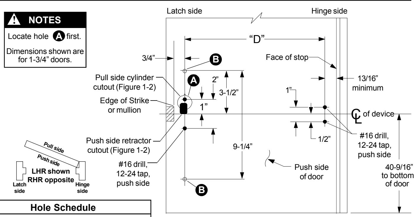
No cylinder ... #16 drill, 12-24 tap, push side Cylinder ...... 1/4" drill, push side; Figure 1-2 shows pull side and push side cylinder cutouts
No pull trim ... Omit
Pull trim ...... pull side of door,
Alum. door: #9 drill, 1/4"-20 tap Metal door: #7 drill, 1/4"-20 tap
| Model | Trim Package |
|---|---|
| EL 1590 | None |
| EL 1591 | 9970 Pull Trim |
| EL 1592 | NL Cylinder |
| EL 1593 | HB Cylinder |
| EL 1594 | 9970 Pull Trim with NL Cylinder |
| EL 1595 | 9970 Pull Trim with HB Cylinder |


Figure 1-1
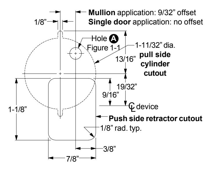
Figure 1-2

2 Cut pushbar to length.
- 2.1. Measure C to C of mounting holes ("D" dimension in Figure 1-1). L L
- 2.2. Subtract 2-13/16" from "D" dimension to determine cut length ("B" dimension in Figure 2). See chart below for minimum "B" dimension.
| Device |
"B"
Dimension |
Minimum"B" | Minimum"B" |
|---|---|---|---|
| Length | Supplied |
Dimension
(non-EL) |
Dimension
(EL) |
|
36"
device |
30-17/32" | 19-1/2" | 29-17/32" |
|
42"
device |
36-17/32" | 19-1/2" | 29-17/32" |
|
48"
device |
42-17/32" | 28-1/2" | 37-17/32" |
- 2.3. Collapse pushbar, tape down in cutoff area, and mark "B" dimension on tape (see Figure 2).
- 2.4. Keep chips out of mechanism by stuffing a rag into end of pushbar before cutting. Keep rag out of the path of the saw. Cut pushbar and channel, deburr, and clean chips from pushbar and channel.
- 2.5. Pull the two rubber bumper strips from the screw grooves, cut off 1" so the bumper strips are 1" shorter than the pushbar, and reinstall bumper strips into screw grooves.
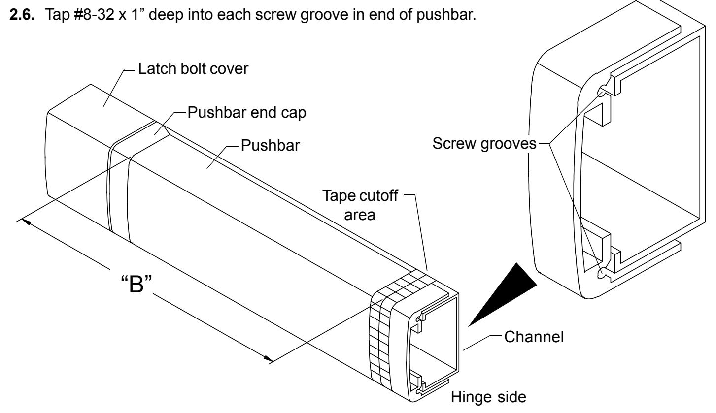
Figure 2
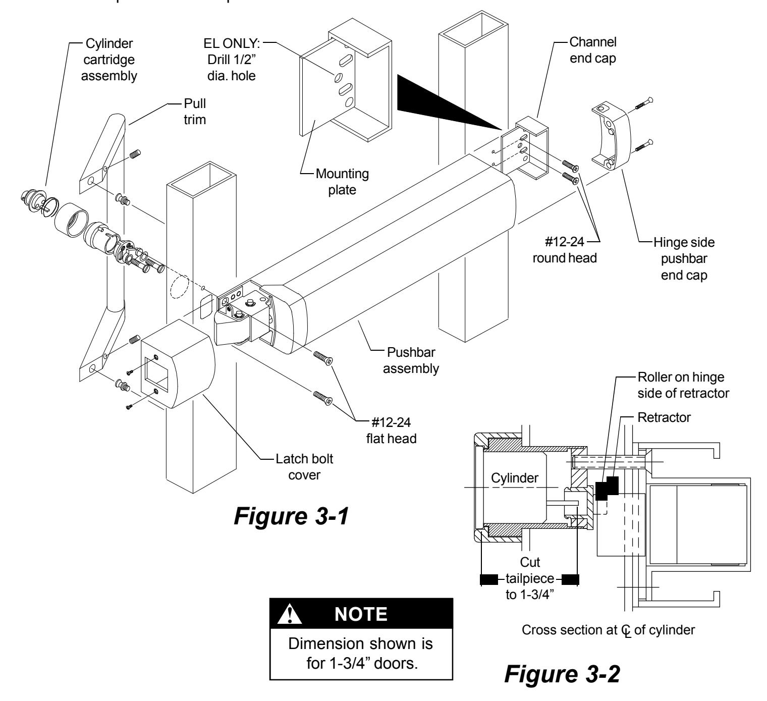
3 Install device.
- 3.1. If using cylinder, cut tailpiece, assemble cylinder cartridge assembly, and install in door.
- 3.2. Install mounting plate (knobs facing stile) and channel end cap with #12-24 round head screws.
- 3.3. If installing an EL device drill 1/2" diameter electrical wiring hole through 3/8" diameter hole in mounting plate and through push side of door.
- 3.4. Slide pushbar assembly into mounting plate on hinge stile.
- 3.5. Attach latch side of pushbar assembly with #12-24 flat head screws.
- 3.6. Wire device (see Step 4), then install latch bolt cover and hinge side pushbar end cap.
- 3.7. If using pull trim, install pull trim.
- 3.8. Install pushbar end caps.
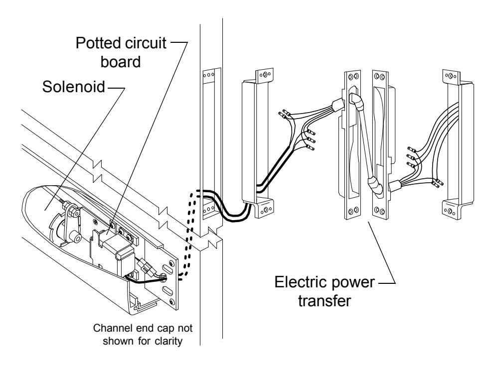
If installing EL device, wire device.
EL1590
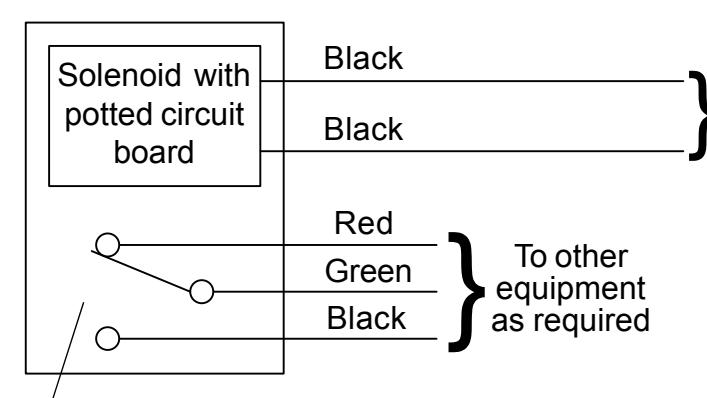
Latch bolt monitor switch. Switch shown with latch bolt fully extended. Switch changes when latch bolt is retracted by pressing the pushbar or applying power to the solenoid.
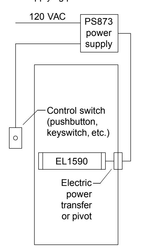
Solenoid must be wired to a PS873 logic board:
If 871-2 logic board, refer to Von Duprin instructions 941352.
If other 873 logic board, refer to Von Duprin instructions 941353.
Solenoid wiring must be 12 AWG, 200 feet maximum, between PS873 and EL1590. Any references to a Von Duprin EL device apply to EL1590 series devices. EL1590 series devices are fail secure locking devices.
Electrical Specifications
Voltage: 24 VDC
Current: 16 A inrush (0.3 sec.)
0.25 A holding
NOTE
The potted circuit board is a protection circuit. It disconnects power from the solenoid if the plunger does not seat within a specified time. To reset the protection circuitry, remove power from the solenoid and reapply.