Falcon 1498 Inactive Device Installation Instructions-English 107314
Open the original PDF document
View PDF

4270107667
1498 Inactive Device
Installation Instructions
Prepare door and Install device.
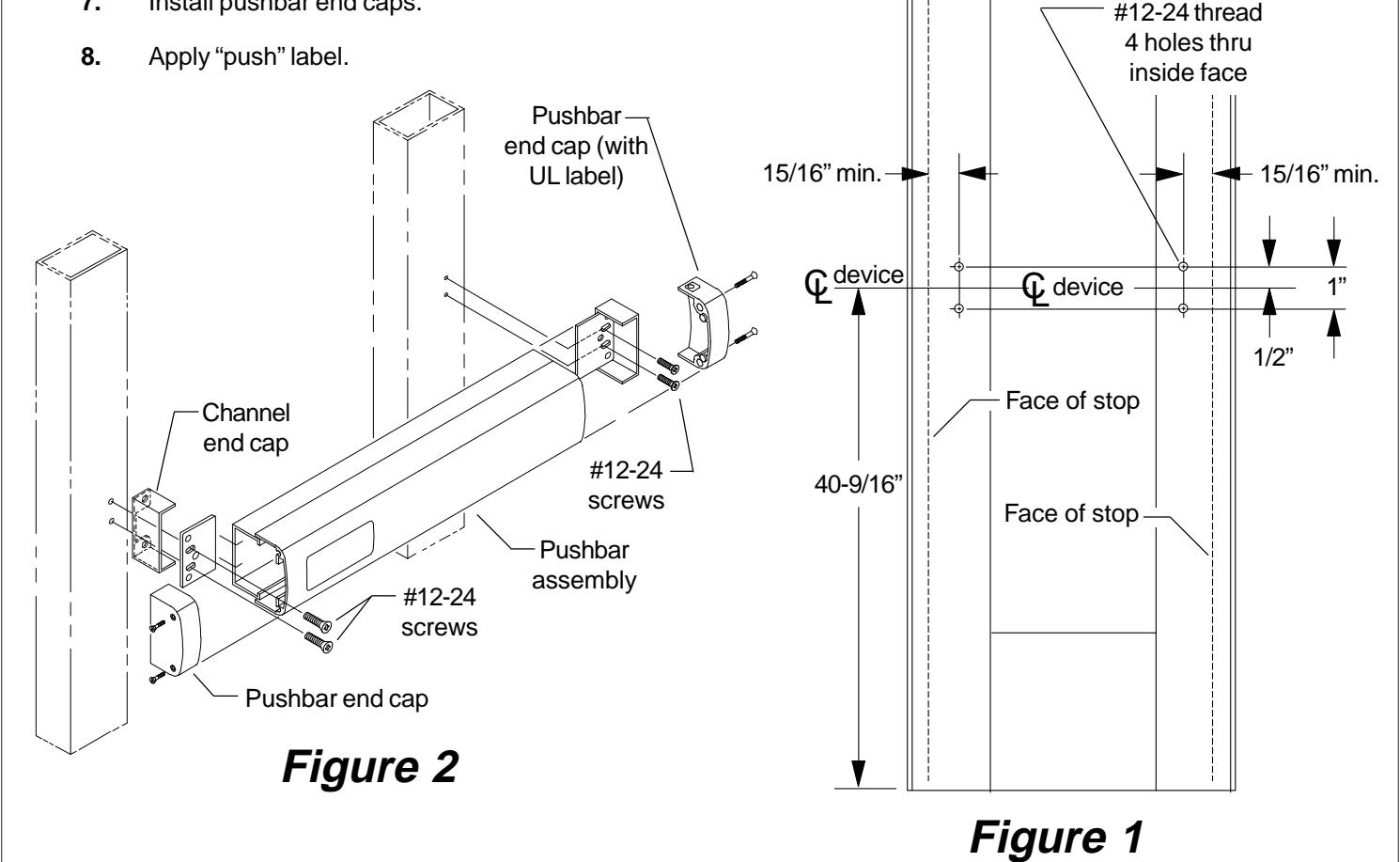
- 1. Prepare door as shown in Figure 1 below.
- 2. Cut pushbar as shown on reverse side of sheet.
- 3. Install mounting plate loosely on hinge stile (knobs facing stile) with #12-24 screws (See Figure 2 below). Do not fully tighten until final adjustments are made.
- 4. Slide pushbar assembly into mounting plate on hinge stile.
- 5. Install mounting plate (knobs facing stile) on lock stile with #12-24 screws.
- 6. Install channel end caps on both ends (knobs of mounting plates fit into channel end caps). Tighten #12-24 screws.
- 7. Install pushbar end caps.

Cut pushbar to length.
- 1. Measure Q to Q of mounting holes ("A" dimension Figure 3).
- 2. Subtract 1/2" from "A" dimension to determine cut length ("B" dimension in Figure 3 and 4). See chart below for minimum "B" dimension.
| Device | "B" Dimension | Minimum "B" |
|---|---|---|
| Length | Supplied | Dimension |
| 36" device | 32-5/8" | 21" |
| 42" device | 38-5/8" | 21" |
| 48" device | 44-5/8" | 30" |
- 3. Tape around channel and pushbar in cutoff area, and mark "B" dimension on tape (see Figure 4).
- 4. Keep chips out of mechanism by stuffing a rag into end of pushbar before cutting. Keep rag out of the path of the saw. Cut pushbar and channel, deburr, and clean chips from pushbar and channel.
- 5. Pull the two rubber bumper strips from the screw grooves, cut off 1" so the bumper strips are 1" shorter than the pushbar, and reinstall bumper strips into screw grooves.
- 6. Tap #8-32 x 1" deep into each screw groove in end of pushbar.
- 7. See reverse side for installation.
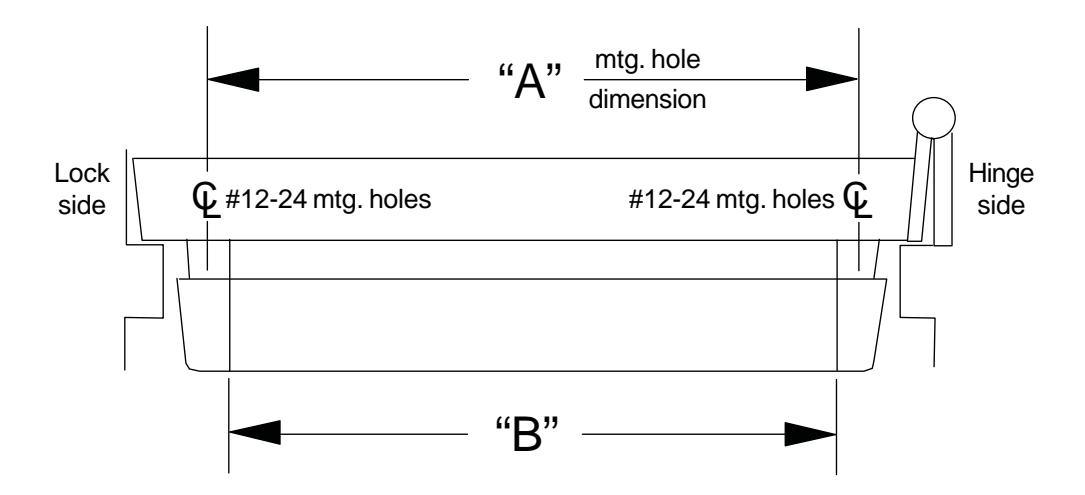
Figure 3
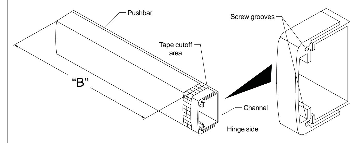
Figure 4