Falcon 1490 Touchbar Concealed Vertical Rod Panic Device Installation Instructions 108144
Open the original PDF document
View PDF

1490 Touchbar
ININST.1090
Concealed Vertical Rod Panic Device
Installation Instructions
Applies to EL and standard 1490, 1491, 1492, 1493, 1494, 1495
1 Prepare door.
| Model |
Trim
Package |
|
|---|---|---|
| 1490 | None | |
| 1491 | 9970 Pull Trim | |
| 1492 | NL Cylinder | |
| 1493 | HB Cylinder | |
| 1494 | 9970 PullTrim with NL Cylinder | |
| 1495 | 9970 Pull Trim with HB Cylinder | |
Hole Schedule
A
No cylinder ... Omit
Cylinder ........ 1/4" drill, 82° countersink
to 25/64" dia., push side; Figure 1-2 shows pull side
cylinder cutout
B
No pull trim ... Omit
Pull trim ........ 5/16" drill, 1/4-20 tap, pull side
Pull Side Cylinder Cutout
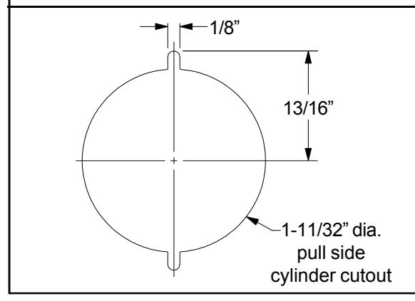

Dimensions shown are for 1-3/4" doors. All cutouts are push side unless otherwise noted.

2 Cut pushbar to length.
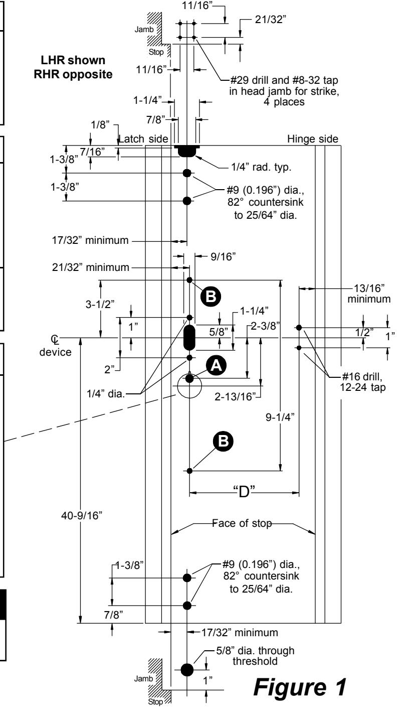
- 2.1. Measure Q to Q of mounting holes ("D" dimension on page 1, Figure 1).
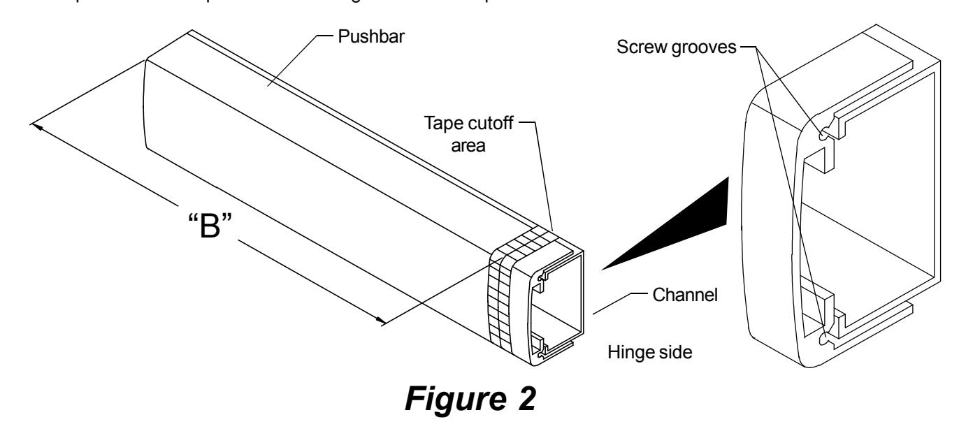
- 2.2. Subtract 5/8" from "D" dimension to determine cut length ("B" dimension in Figure 2). See chart below for minimum "B" dimension.
| Device | "B" Dimension | Minimum "B" | Minimum "B" |
|---|---|---|---|
| Length | Supplied | Dimension (non-EL) | Dimension (EL) |
| 36" device | 32-5/8" | 24-5/16" | 31-3/8" |
| 42" device | 38-5/8" | 24-5/16" | 31-3/8" |
| 48" device | 44-5/8" | 33-5/16" | 40-1/4" |
- 2.3. Collapse pushbar, tape down in cutoff area, and mark "B" dimension on tape (see Figure 2).
- 2.4. Keep chips out of mechanism by stuffing a rag into end of pushbar before cutting. Keep rag out of the path of the saw. Cut pushbar and channel, deburr, and clean chips from pushbar and channel.
- 2.5. Pull the two rubber bumper strips from the screw grooves, cut off 1" so the bumper strips are 1" shorter than the pushbar, and reinstall bumper strips into screw grooves.
- 2.6. Tap #8-32 x 1" deep into each screw groove in end of pushbar.
3 Change handing of device if necessary (non-EL devices only).
- 3.1. Remove pushbar and channel from activating assembly.
- 3.2. Remove washers, retaining rings, and link from activating assembly.
- 3.3. Reposition link on activating rod and lift lever to hand activating assembly as required.
- 3.4. Reinstall washers and retaining rings.
- 3.5. Reinstall pushbar and channel.
Activating rod Retaining rings Activating assembly Lift lever—and washers RHR S RHR LHR S LHR LHR LHR LHR RHR
Figure 3
Note: 1490 pushbar labels (only handed part of device): 4270107320. Gold w/black le
4270107320 Gold w/black letters RHR 4270107321 Black w/silver letters RHR
4270107322 Gold w/black letters LHR 4270107323 Black w/silver letters LHR
4 Install device.
- 4.1. Install strike into frame.
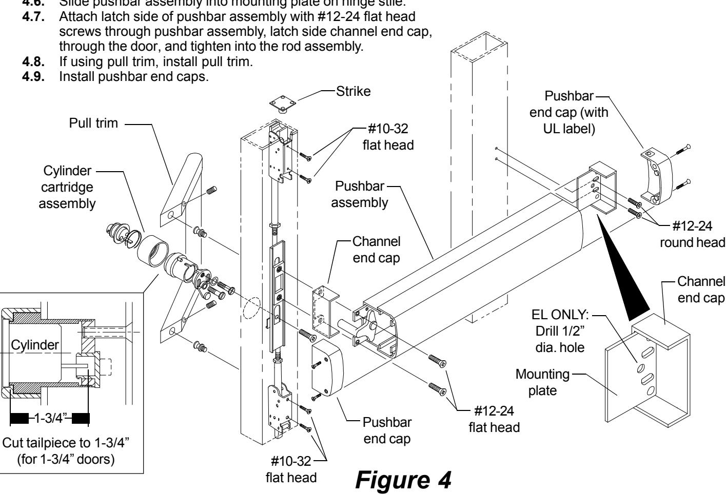
- 4.2. Install rod assembly into lock stile and secure top and bottom latches using #10-32 flat head screws.
- 4.3. If using cylinder, cut tailpiece, assemble cylinder cartridge assembly, and install in door.
- 4.4. Install mounting plate (knobs facing stile) and channel end cap with #12-24 round head screws.
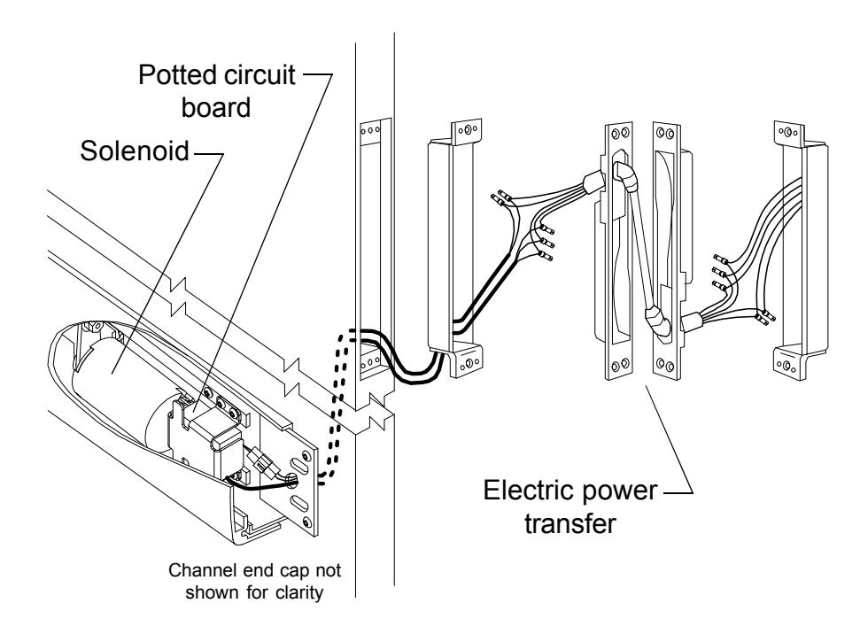
- 4.5. If installing an EL device, drill 1/2" diameter electrical wiring hole through 3/8" diameter hole in mounting plate and through push side of door.
- 4.6. Slide pushbar assembly into mounting plate on hinge stile.
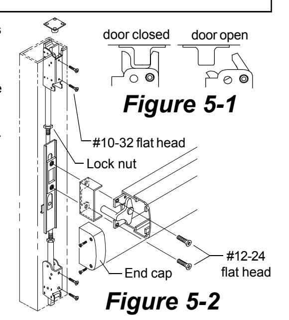
5 Adjust top rod if necessary.
Note: Test the door to make sure the top latch will lock when the door is closed and will open properly when the pushpad is depressed. See Figure 5-1 for correct latch bolt position with door open and closed.
flat head
If the top latch bolt will not release when the pushpad is pushed and the door will not open, the rod is adjusted too short.
If the door opens okay, but the door will not lock, the top rod is too long.
To adjust top rod length (Figure 5-2):
- 5.1. Remove the end cap.
- 5.2. Remove the two #12-24 latch side device mounting screws.
- 5.3. Remove the two #10-32 top latch mounting screws and the two #10-32 bottom latch mounting screws.
- 5.4. Slide the rods assembly out the top of the door until the top rod lock nut is accessible. If lock nut is not accessible, remove door.
- 5.5. Loosen the top rod lock nut.
- 5.6. Lengthen or shorten rod length by threading latch up or down.
- 5.7. Adjust rod until latchbolt functions as shown in Figure 5-1.
- 5.8. Reassemble device and test for proper function.
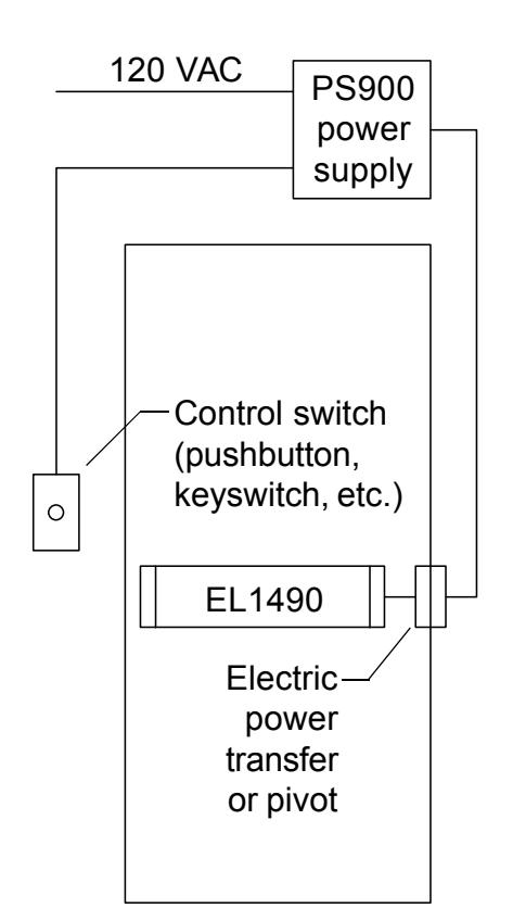
6 If installing EL device, wire device.
EL1490
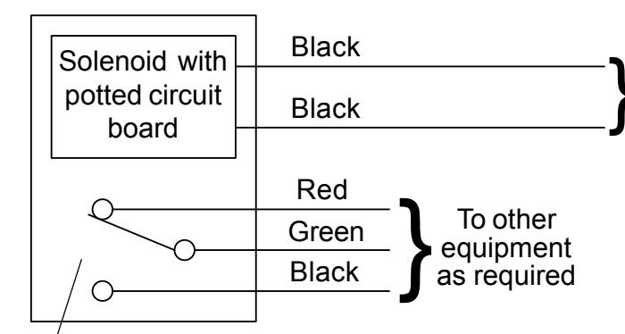
Solenoid must be wired to a PS914 power supply with a 900-2RS or 900-4RL option board installed.
- Latch bolt monitor switch. Switch shown with latch bolt fully extended. Switch changes when latch bolt is retracted by pressing the pushbar or applying power to the solenoid.
Solenoid wiring must be 12 AWG, 200 feet maximum, between PS914 and EL1490. Any references to a Von Duprin EL device apply to EL1490 series devices. EL1490 series devices are fail secure locking devices.
Electrical Specifications
Voltage: 24 VDC
Current: 16 A inrush (0.3 sec.)
0.25 A holding
NOTE
The potted circuit board is a protection circuit. It disconnects power from the solenoid if the plunger does not seat within a specified time. To reset the protection circuitry, remove power from the solenoid and reapply.