FCBP-Product-Catalog-2020
Open the original PDF document
View PDF

2020 Product Catalog
NOTES
| _ | |
|---|---|

TABLE OF CONTENTS
|
Exit
Devices |
3690 SERIES | – Concealed Vertical Rod Exit Device1 | ||
|---|---|---|---|---|
| FL3690 SERIES | – | Impact Rated Concealed Vertical Rod Exit Device2 | ||
| 3790 SERIES | – |
Rim Latching Exit Device
3 |
||
| 3190 SERIES | – |
Recess Mounted Concealed Vertical Rod Exit Device
4 |
||
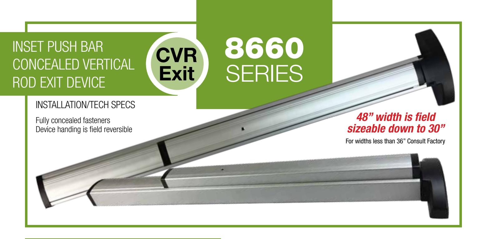
| 8660 SERIES | – | Inset Bar Concealed Vertical Rod Exit Device5 | ||
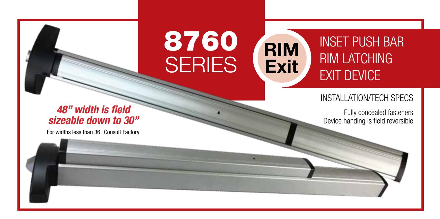
| 8760 SERIES | – |
Inset Bar Rim Latching Exit Device
6 |
||
| 8860 SERIES | – |
Inset Bar Mortise Locking Exit Device
7 |
||
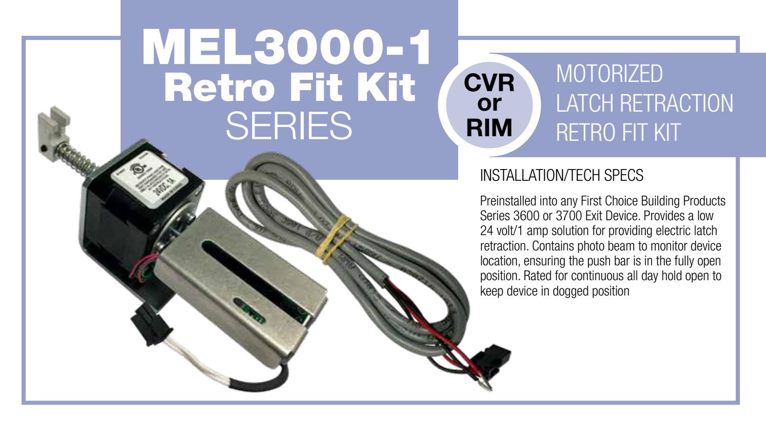
| Accessories | MEL3000-1 | – | Electric Latch Retraction Retrofit Kit8 | |
| PSMEL2000 | – | 1 Amp Power Supply (for 2 Doors)9 | ||
| PSMEL1500 | – |
1 Amp Power Supply (for 1 Door)
10 |
||
| ACCESS8 | – | 8 Door Access Control System11 | ||
| ACCESS8 ACC | – | 8 Door Access Control System Accessories12 | ||
| QC-CAB | – |
Quick Cable Connectors
13 |
||
| L3 SERIES | – |
Lever Trim
14 |
||
| RM370 | – |
Security Mullion
15 |
||
| KRM370 | – | Keyed Removable Mullion16 | ||
| SM500 | – | Surface Mounted Rim Electric Strike17 | ||
| EPT3100 | – |
EPT Concealed Rigid Power Transfer
18 |
||
| EPT300 | – | EPT Concealed Power Transfer19 | ||
| EMT300 | – | EMT Surface Mount Power Transfer19 | ||
| AL36 | – |
Alarm Kit
20 |
||
| SW300-2CA | – | Bracket Mounted Signal Switch21 | ||
|
Cylinders
Hinges |
CD3000 | – | Cylinder Dogging Kit22 | |
| 841 | – |
Rim Type Key Cylinder
23 |
||
| 9052-T | – | Thumb Turn Rim Type Key Cylinder23 | ||
| M100 | – | Mortise Type Key Cylinder23 | ||
| FC110 | – | Fully Concealed Continuous Hinges24 | ||
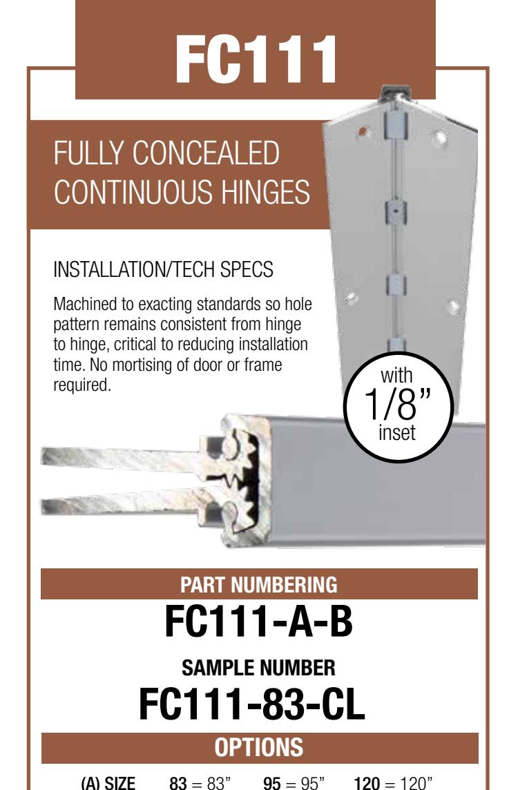
| FC111 | – | Fully Concealed Continuous Hinges (1/8" inset)24 | ||
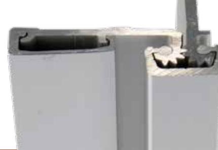
| FC240 | – | Fully Concealed Continuous Hinges (3/32" inset)25 | ||
| FC530 | – | Half Surface Continuous Hinges25 | ||
| FC570 | – | Half Surface Continuous Hinges26 | ||
| WARRANTY | – |
Warranty & Frequently Asked Questions
27 |
CONCEALED VERTICAL ROD EXIT DEVICE

3690 SERIES
INSTALLATION/TECH SPECS
Non-Handed; Rotational Top Strike Adjustment; 1/2" Bottom Latch Bolt Throw
PART NUMBERING
A/36/B/C-D/E
SAMPLE NUMBER MEL369236-CL96
OPTIONS
(A) ACCESSORIES
- MEL = Motorized Electric Latch Retraction
- SW = Signal Switch
- CD = Interior Cylinder Dogging
- CDAL = Alarm Function with Cylinder Off/On
(B) FUNCTION
- 90 = Exit Only
- 91 = With 1" Round Offset Pull (10" Centers)
- 92 = Prepped for Ext. Key Cylinder
- 93 = Prepped for Ext. Key Cylinder with Cylinder Included
(C) SIZE
- 30 = 30"
- 36 = 36"
- 42 = 42"
- 48 = 48"
- XX = Special
(D) FINISH
- BR = Dark Bronze
- BL = Black
- SP = Special
Note: End Caps are always Black Enamel
(E) SPECIAL HEIGHT
XX = Specify height (Max. 96" tall) (For doors other than 7 feet)
CODE/AGENCY LISTINGS
- Grade 1 listed under national standard ANSI/BHMA 156.3
- UL File #SA12590 for UL 305
APPLICATIONS
- Schools
- Convention Centers
- Office Buildings
- Churches
- Retail Spaces, Etc.
DOOR/ or OTHER SIZES
- 30" to 48" Standard
- Door Heights up to 9' Standard
- Custom Sizes Available
- Door Stile Widths as Narrow as 2"
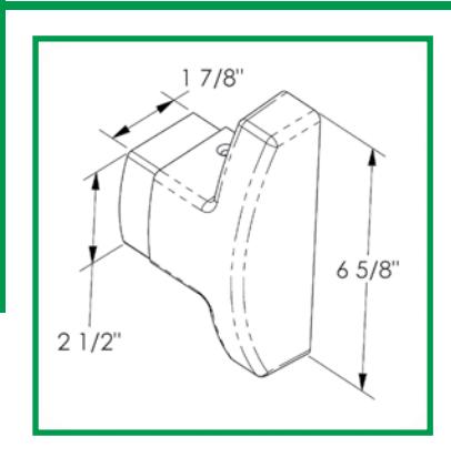
DIMENSIONS
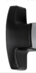
- 21/2" Push Bar Height
- 40<sup>5</sup>/<sub>8</sub>" Centerline Height Typical
- Center Case Cover -6<sup>5</sup>/<sub>8</sub>" Tall by 1<sup>1</sup>/<sub>4</sub>" Wide
PRODUCT MATERIALS
- Anodized Aluminum Push Bar and Channel
- Die Cast Aluminum End Caps
- Stainless Steel Strikes
- Steel Latch Bolts
- 3/8" Steel Vertical Rods
SHIPPING
FOB Our Dock; Shipping Weight Standard 36" with Standard Option – 11.4#
CONDENSED SPECIFICATION
- Exit Device shall be First Choice series 3600 Concealed Vertical Rod.
- Designed for use on aluminum storefront doors only and not intended for wooden doors.
- Narrow Stile model utilizing low profile touch bar projecting 3" from face of door.
- Device shall use 3/8" steel vertical rods with steel latch bolts engaging stainless steel strikes to lock two points in the opening.


FL3690 SERIES
CONCEALED VERTICAL ROD EXIT DEVICE CVR
The FL Series is approved for hurricane impact when used with an appropriately tested and rated door system*.
INSTALLATION/TECH SPECS
Non-Handed; Rotational Top Strike Adjustment; 1/2" Bottom Latch Bolt Throw
CODE/AGENCY LISTINGS
- Grade 1 listed under national standard ANSI/BHMA 156.3
- UL File #SA12590 for UL 305
APPLICATIONS
- Schools
- Convention Centers
- Office Buildings
- Churches
- Retail Spaces, Etc.
DOOR/ or OTHER SIZES
- 30" to 48" Standard
- Door Heights up to 9' Standard
- Custom Sizes Available
- Door Stile Widths as Narrow as 2"
DIMENSIONS
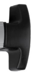
- 21 /2" Push Bar Height
- 415 /16" Centerline Height Typical
- Center Case Cover 65 /8" Tall by 11 /4" Wide
PRODUCT MATERIALS
- Anodized Aluminum Push Bar and Channel
- Die Cast Aluminum End Caps
- Stainless Steel Strikes
- Steel Latch Bolts
- 3/8" Steel Vertical Rods
SHIPPING
• FOB Our Dock; Shipping Weight Standard 36" with Standard Option – 11.4#
CONDENSED SPECIFICATION
- Exit Device shall be First Choice series 3600 Concealed Vertical Rod.
- Designed for use on aluminum storefront doors only and not intended for wooden doors.
- Narrow Stile model utilizing low profile touch bar projecting 3" from face of door.
- Device shall use 3/8" steel vertical rods with steel latch bolts engaging stainless steel strikes to lock two points in the opening.
WARRANTY (See page 23 for complete warranty information)
* Manufactured door must meet impact testing requirements. Contact your door manufacturer.
PART NUMBERING
A/FL36/B/C-D/E
SAMPLE NUMBER
MELFL369236-CL96
OPTIONS
(A) ACCESSORIES
MEL = Motorized Electric Latch Retraction
SW = Signal Switch
CD = Interior Cylinder Dogging
(B) FUNCTION
90 = Exit Only
91 = With 1" Round Offset Pull (10" Centers)
92 = Prepped for Ext. Key Cylinder
93 = Prepped for Ext. Key Cylinder with Cylinder Included
(C) SIZE
30 = 30"
36 = 36"
42 = 42"
48 = 48"
XX = Special
(D) FINISH
CL = Clear
BR = Dark Bronze
BL = Black
SP = Special
Note: End Caps are always Black Enamel
(E) SPECIAL HEIGHT
XX = Specify height (Max. 96" tall) (For doors other than 7 feet)

2
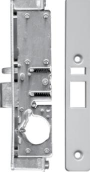
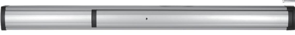
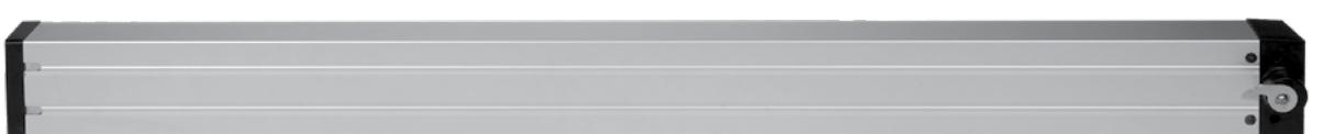
RIM LATCH EXIT DEVICE

3790 SERIES
INSTALLATION/TECH SPECS
Non-Handed:
1" Steel Latch Bolt with 1/2" Throw
PART NUMBERING
A/37/B/C-D
SAMPLE NUMBER MEL379236-CL
OPTIONS
(A) ACCESSORIES
MEL = Motorized Electric Latch Retraction
SW = Signal Switch
CD = Interior Cylinder Dogging
(B) FUNCTION
90 = Exit Only
91 = With 1" Round Offset Pull (10" Centers)
92 = Prepped for Ext. Key Cylinder
93 = Prepped for Ext. Key Cylinder with Cylinder Included
(C) SIZE
30 = 30"
36 = 36"
42 = 42"
48 = 48"
XX = Special
(D) FINISH
BL = Black
SP = Special
Note: End Caps are always Black Enamel
CODE/AGENCY LISTINGS
- Grade 1 listed under national standard ANSI/BHMA 156.3
- UL File #SA12590 for UL 305
APPLICATIONS
- Schools
- Malls
- Government Facilities
- Churches
- Retail Spaces, Etc.
DOOR/ or OTHER SIZES
- 30" to 48" Standard
- Custom Sizes Available
- Door Stiles Widths as Narrow as 2"
DIMENSIONS
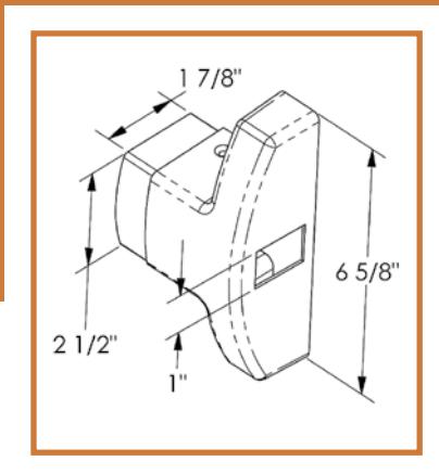
- 21/2" Push Bar Height
- 41<sup>5</sup>/<sub>16</sub>" Centerline Height Typical
- Center Case Cover -6<sup>5</sup>/<sub>8</sub>" Tall by 1<sup>1</sup>/<sub>4</sub>" Wide
PRODUCT MATERIALS
- Anodized Aluminum Push Bar and Channel
- Die Cast Aluminum End Caps
- Stainless Steel Strikes
- 1" Steel Latch Bolt with 1/2" Throw
SHIPPING
FOB Our Dock; Shipping Weight Standard 36" with Standard Option – 8.9#
CONDENSED SPECIFICATION
- The 3700 Series Exit Devices shall be designed to be used on aluminum doors only and are not intended for wooden doors.
- Exit device shall be First Choice Series 3700 Rim Latching narrow stile model utilizing low profile touch bar projecting 3" from face of the door.
- Device shall use 1" steel latching bolt (1/2" throw) engaging a stainless steel roller strike for locking.
- 3700 Series Devices can be resized in the field. (For assistance call 800-793-4544)

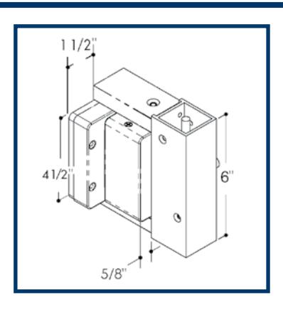
3190 SERIES

RECESS MOUNTED CVR EXIT DEVICE
INSTALLATION/TECH SPECS
Non-Handed; Rotational Top Strike Adjustment; 1/2" Bottom Latch Bolt Throw

CODE/AGENCY LISTINGS
- Grade 1 listed under national standard ANSI/BHMA 156.3
- UL File #SA12590 for UL 305
APPLICATIONS
- Schools
- Convention Centers
- Office Buildings
- Churches
- Retail Spaces, Etc.
DOOR/ or OTHER SIZES
- 30" to 48" Standard
- Door Heights up to 9' Standard
- Custom Sizes Available
- Door Stiles Widths as Narrow as 2"
DIMENSIONS
- 41 /2" Push Bar Height
- 11 /2" Projection
- 413 /32" Centerline Height Typical
PRODUCT MATERIALS
- Anodized Aluminum Push Bar and Channel
- Die Cast Aluminum End Caps
- 3/8" Steel Vertical Rods
- Hardened Steel Latch Bolts
SHIPPING
• FOB Our Dock; Shipping Weight Standard 36" with Standard Option – 15#
(B) FUNCTION
- 90 = Exit Only
- 92 = Prepped for Ext. Key Cylinder
- 93 = Prepped for Ext. Key Cylinder with Cylinder Included
PART NUMBERING
A/31/B/C-D-E
SAMPLE NUMBER
MEL319236-CL-96
OPTIONS
(A) ACCESSORIES
MEL = Motorized Electric Latch Retraction
SW = Signal Switch
D = Dummy Device (Inactive)
(D) FINISH
CL = Clear
BR = Dark Bronze
BL = Black
SP = Special
Note: End Caps are always Black Enamel
(E) SPECIAL HEIGHT
XX = Specify height (Max. 96" tall) (For doors other than 7 feet)
SPECIAL LATCHES
H = Hex bottom
3690P= Pullman style bottom
P3690= Pullman style top
(C) SIZE
24 = DO width 36" – 48"
Muntin length = specify door opening Filler bar length (12" standard) = specify length
XX = Special width consult factory
INACTIVE DOORS
Muntin material up to 48" clear or dark bronze Push bar/filler bar material up to 48" long
CONDENSED SPECIFICATION
- Exit device shall be First Choice Building Products Series 3100 concealed Vertical rod narrow stile model utilizing a low profile touch bar projecting less than 11 /2" from face of the door.
- The device shall use 3 /8" steel vertical rods operating hardened steel latch rotational adjustment for proper door alignment.
- The bottom latch will be a spring powered to ensure engagement with the threshold.
- The device push bar and base shall be 6063 hardened aluminum in anodized finishes. The device shall be capable of operation by external key cylinder with night latch or hold back settings.
- The device shall be capable fo desengagement by a single point, quarter turn dogging.
WARRANTY (See page 23 for complete warranty information

4
PART NUMBERING
A/86/B/C-D-E
SAMPLE NUMBER
MEL866036-CL-96
OPTIONS
(A) MISC. OPTIONS
MEL = Motorized Electric Latch Retraction
AL = Alarm Board
SW = Signal Switch
CD = Cylinder Dogging
(B) FUNCTIONS
60 = Exit Only
61 = With 1" Round Offset Pull (10" Centers)
62 = Prepped for Ext. Key Cylinder
63 = Prepped for Ext. Key Cylinder with Cylinder Included
(C) DOOR WIDTH
36 = 36" (standard)
48 = 48"
XX = Special Width (consult factory)
(D) FINISH
CL = Clear
BR = Dark Bronze
BL = Black
(E) SPECIAL HEIGHT
XX = (consult factory)
CODE/AGENCY LISTINGS
- Grade 1 listed under national standard ANSI/BHMA 156.3
- UL File #SA12590 for UL 305
APPLICATIONS
Aluminum doors in high traffic areas such as:
- High Schools
- Theaters
- Post Offices
- Churches
- Retail Spaces, Etc.
DOOR/ or OTHER SIZES
- 30" to 48" Standard; Field Sizable as Narrow as 30"
- Custom Sizes Available
- Suitable for Narrow, Medium, and Wide Stile Doors
DIMENSIONS
- 21 /2" Push Bar Height
- 11 /4" Standard Door Thickness
PRODUCT MATERIALS
- Anodized Aluminum Push Bar and Channel
- Die Cast Aluminum End Caps
SHIPPING
• FOB Our Dock; Shipping Weight with Standard Options – 10#
CONDENSED SPECIFICATION
- Exit Device shall be First Choice Series 8860 Concealed Vertical Rod Exit Device.
- Model utilizing low profile touchbar projecting 3" from the face of door.
- Device shall be field resizeable and reversible.

CODE/AGENCY LISTINGS
- Grade 1 listed under national standard ANSI/BHMA 156.3
- UL File #SA12590 for UL 305
APPLICATIONS
Aluminum doors in high traffic areas such as:
- High Schools
- Theaters
- Post Offices
- Churches
- Retail Spaces, Etc.
DOOR/ or OTHER SIZES
- 30" to 48" Standard; Field Sizeable as Narrow as 30"
- Custom Sizes Available
- Suitable for Narrow, Medium, and Wide Stile Doors
DIMENSIONS
- 21 /2" Push Bar Height
- 11 /4" Standard Door Thickness
- 1" Steel Latch Bolt (1/2" Throw)
PRODUCT MATERIALS
- Anodized Aluminum Push Bar and Channel
- Die Cast Aluminum End Caps
SHIPPING
• FOB Our Dock; Shipping Weight with Standard Options – 10#
PART NUMBERING
A/87/B/C-D
SAMPLE NUMBER
MELDL876036-CL
OPTIONS
(A) MISC. OPTIONS
MEL = Motorized Electric Latch Retraction
AL = Alarm Board
SW = Signal Switch
CD = Cylinder Dogging
DL = Dead Latch
(B) FUNCTIONS
60 = Exit Only
61 = With 1" Round Offset Pull (10" Centers)
62 = Prepped for Ext. Key Cylinder
63 = Prepped for Ext. Key Cylinder with Cylinder Included
(C) DOOR WIDTH
36 = 36" (standard)
48 = 48"
XX = Special Width (consult factory)
(D) FINISH
CL = Clear
BR = Dark Bronze
BL = Black
CONDENSED SPECIFICATION
- Exit Device shall be First Choice Series 8760 Rim Latching Exit Device.
- Model utilizing low profile touchbar projecting 3" from the face of door.
- Device shall field resizeable and reversible.
WARRANTY (See page 23 for complete warranty information)
6
MORTISE LOCKING EXIT DEVICE

8860 SERIES
INSTALLATION/TECH SPECS
Fully concealed fasteners Device handing is field reversible
PART NUMBERING
A/8860/B-C/D/E/F
SAMPLE NUMBER MEL886036-CLR01S1
(E) BACKSET
01 = 3/32"
02 = 1-1/8"
03 = 1 - 1/2"
(F) STRIKE TYPE
S1 = 2" Standard
S2 = 3" Extended
S3 = 4" Tall Strike
OPTIONS
(A) ACCESSORIES
MEL = Motorized Electric Latch Retraction
(B) DOOR WIDTH
36 = 36 inches
42 = 42 inches
48 = 48 inches
(C) FINISH
CL = Clear
BR = Dark Bronze
BL = Black
(D) HAND
L = Left Hand
CODE/AGENCY LISTINGS
- Grade 1 listed under national standard ANSI/BHMA 156.3
- Ul File #SA12590 for Ul 305
APPLICATIONS
Aluminum doors in high traffic areas such as:
- High Schools
- Theaters
- Post Offices
- Churches
- Retail Spaces, Etc.
DOOR/ or OTHER SIZES
- 30" to 48" Standard; Field Sizeable as Narrow as 30"
- Custom Sizes Available
- Suitable for Narrow, Medium, and Wide Stile Doors
DIMENSIONS
- 21/2" Push Bar Height
- 11/4" Standard Door Thickness
PRODUCT MATERIALS
- Anodized Aluminum Push Bar and Channel
- Die Cast Aluminum End Caps
- Heavy Duty Steel Mortise Deadlatching Lockset in Multiple Backsets
SHIPPING
FOB Our Dock; Shipping Weight with Standard Options — 10#
CONDENSED SPECIFICATION
- Exit Device shall be First Choice Series 8860 Mortise Latching Exit Device.
- Model utilizing low profile touchbar projecting 3" from the face of door.
- Device shall use mortise deadlatching lockset.

APPLICATIONS
Areas requiring monitored access and/or security clearance such as:
- Schools
- Hospitals
- Nursing Homes
- Stock Rooms
- Office Buildings, etc.
DOOR/ or OTHER SIZES
- 30" up to 52"
- Door Heights up to 9'
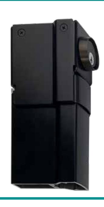
PRODUCT MATERIALS
Internal motor made from aluminum and steel with heavy duty circuit board
COMPATIBLE POWER SUPPLIES
PSMEL2000 = Powers 2 Devices 24 volt/1 amp PSMEL1500 = Powers 1 Device
SMELT500 = Powers T Device 24 volt/1 amp
PART NUMBERING
MEL3000-1
CONDENSED SPECIFICATION
- The Exit Device shall be motorized by First Choice Building Products.
- Device shall be a First Choice Building Products Series MEL3000 motor driven exit device.
- The device shall contain a photo beam sensory array for monitoring. that a push bar has been fully retracted.
- MEL3000 motor driven exit devices shall be rated for continuous duty. to hold the exit device in the dogged and open position indefinitely.

12/24V – 1 AMP POWER SUPPLY FOR 2 DOORS
PSMEL2000 SERIES
DIMENSIONS 13"H x 12.5"W x 3.5"D
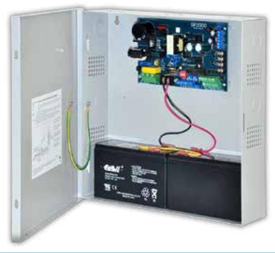
FCBP's NEW SMART SELF-DIAGNOSING POWER SUPPLY
Operates a pair of doors with two low current exit devices simultaneously or independently control two single door leafs
• Two (2) 24 VDC individually controlled lock outputs rated @ 1 amp each. Load connected not to exceed 1 amp.
• One (1) 24VDC @ .08 amps filtered regulated auxiliary output. (Not affected by FACP trigger) • One (1)12 VDC @ .05 amp filtered regulated auxillary output. (Not affected by FACP trigger) Note: Total combined current for the 24VDC outputs may not
OUTPUTS
PART NUMBERING
PSMEL2000
NOTE: Wiring methods shall be in accordance with the National Electrical Code/NPFA 70/NFPA 72 ANSI, and with all local codes and authorities having jurisdiction. Product is intended for indoor use only.
PSMEL2000 SMART VISUAL INDICATORS
- Output 1 & 2 = Red (ON) input LEDs indicate panic device status is energized (rapid blink/short or over current) (slow blink/open circuit)
- FAI = Green (ON) FACP Input Triggered (Alarm Condition)
- Battery Trouble = Red (ON) Battery Normal (slow blink/bad battery or no battery)
- AC Trouble = Green (ON) AC normal (slow blink/AC low or missing)
CONDENSED SPECIFICATION
- PSMEL2000 shall operate up to two (2) 24VDC panic hardware devices simultaneously
- Each lock output shall have an adjustable relock delay timer
- It shall control a pair of doors simultaneously or independently two doors
- Relay for each output to trigger external relays, ADA push plate switches, etc.
- Delayed follower relays shall control automatic door operators for doors that are always locked or for doors that are unlocked during the business day
- Two un-switched auxillary voltage outputs shall provide/remove power to the lock outputs when activated
- A programmable FACP interface shall provide power/remove power to the lock outputs when activated
- Shall have LED status indicators monitor AC, FACP status & for lock output wiring supervision
- Intelligent logic shall provide protection against accidental shorting of lock outputs
CODE/AGENCY LISTINGS
- UL File for Access Control
- Systems Units (UL 294) CUL Listed CSA Standard C22.2
- No. 205-M983, Signal Equipments CSFM California State Fire Marshal Approved
BATTERY BACKUP
- Built-in charger for sealed lead acid or gel type batteries
- Automatic switch over to stand-by battery when AC fails
- Maximum charge current .65 amps
- 4AA batteries will make emergency stand-by at least 30 minutes
INPUT
- Input 115VAC 60Hz, 2.5 amp or 230VAC, 50Hz, 1.5 amps
- Two (2) N.O. Trigger Inputs
VISUAL INDICATORS
exceed 1.75 amp.
accessories
• Two (2) follower N.O. outputs for controlling ADA actuators/
• Two (2) momentary operator activation outputs
• Trouble output relay for indicating low/AC Voltage and battery trouble.
- Output 1 (On/Over/Open)
- Output 2 (On/Over/Open)
- FAI (On/Off)
- Battery (On/Off)
- AC Trouble (On/Low or Missing)
- AC Power (On/Off)

PSMEL1500 SERIES
12/24V – 1 AMP POWER SUPPLY FOR 1 DOOR
Operates one door and one low current exit device
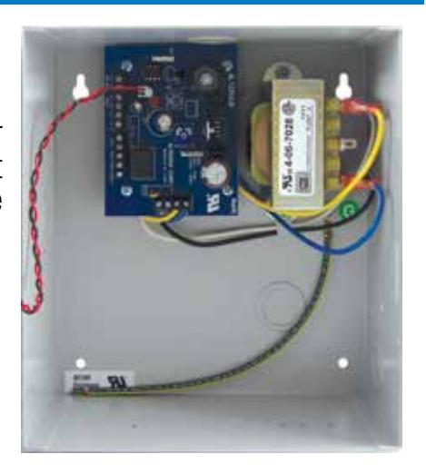
DIMENSIONS 8.5"H x 7.5"W x 3.5"D
VISUAL INDICATORS
- Green AC Power LED indicates 115/AC present
- Red LED indicates presence of 24VDC
CODE/AGENCY LISTINGS
- UL File for Access Control Systems Units (UL 294)
- CUL Listed CSA Standard C22.2 No. 205-M1983, Signal Equipments
- CSFM California State Fire Marshal Approved
BATTERY BACKUP
- Built-in charger for sealed lead acid or gel type batteries
- Automatic switch over to stand-by battery when AC fails
- Maximum charge current .4 amps
- When 4AA batteries are used, capacity for emergency stand-by is at least 30 minutes
INPUT
- Input 115VAC 60Hz, 2.5 amp or 230VAC, 50Hz, 15 amps
- One (1) N.O. Trigger Inputs
OUTPUTS
- 12 VDC or 24VDC selectable outputs
- 1 amp supply current
- One (1) Fail-Safe (lock +) supplies power when unit is not being triggered
- One (1) Fail-Secure (strike +) supplies power when unit is being triggered
- (Com –) supplies negative power
CONDENSED SPECIFICATION
- PSMEL1500 shall operate up to one (1) 24VDC panic hardware device.
- In addition, an auxiliary power output shall provide power for accessory devices such as card readers, key-pads, REX PIRs, electronic timers, relays, etc.
PART NUMBERING
PSMEL1500
NOTE: Wiring methods shall be in accordance with the National Electrical Code/NPFA 70/NFPA 72 ANSI, and with all local codes and authorities having jurisdiction. Product is intended for indoor use only.

8 DOOR ACCESS CONTROL SYSTEM

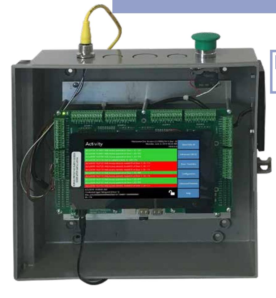
PART NUMBERING
FCHP1
This user friendly stand-alone plug'n'play touch screen interface makes it easy to enroll/remove proximity cards on one or multiple doors. Now it's simple to view audit trails, id's, create schedules, access levels, expiration dates, set vacations, overrided doors, set relocking intervals or even lock down/open all doors with a touch of a button.
FEATURES
- May be used as a stand-alone or can be integrated into existing systems.
- Audit trail enables monitoring activities on every access/attempt which can be archived by downloading onto one of four built-in USB ports.
- Quick Edit ID Mode allows easily adding/removing users (bulk or single) to the system using the state-of-the-art touch screen technology.
- Advanced Edit Mode makes it simple to add access levels, hourly schedules, 1st arrival, along with all other full service door control options.
- On board wiring diagrams via USB internal memory stick for Readers, RTE connections, Maglocks, Electric Strikes etc.
- Multiple units can be linked for control of more than 8 doors.
- WIFI compatibility enables out buildings to be controlled without hard wiring (see Weigand Bridge, page 12.)
APPLICATIONS
-
For use with any electrified entry way. The Access8 Door Access Control System is an affordable security solution for smaller venues such as:
- Office Complexes Religious Facilities
-
Day Care Centers Senior Care Centers
- Schools Store Fronts, etc.
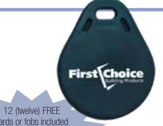
ACCESSORIES

cards or fobs included with purchase of each Access8. Full color printing is included on cards and fobs.
PART NUMBER
FCHP-F-01
Key Fobs are available with the same options as the proximity cards.
HID PROXIMITY CARDS HID KEY FOBS PART NUMBER
FCHP-C320
Cards are factory programmed for HID, AWID, Farpointe and other popular bit structures. Numbering can include facility code and are typically standard 26 bit format but can be custom formatted.
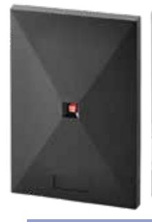
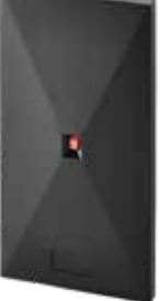
PROXIMITY CARD READERS
PART NUMBER
FCHP-CR500 FCHP-CR300 (Standard Stiles) (Narrow Stiles)
Readers are compatible with most low frequency proximity cards and tag (RFID) technologies and comply with Wiegand communication protocol.
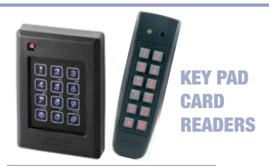
PART NUMBER
FCHP-KP1 AC-G44 (Standard Stiles) (Narrow Stiles)
Serves as low frequency reader for standard cards, fobs and tags. Keypad also serves as a secure entry system for short term and long term access.
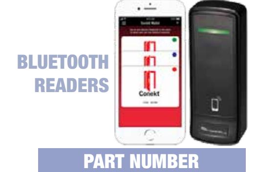
FCHP-BTR
Bluetooth reader supports Smartphone Mobile Access Credentials as well as HID proximity cards and fobs. Cost for each credentialed app for phones is not included.
WIEGAND BRIDGE
PART NUMBER
FCHP-WB100
Wiegand Bridge for out buildings that prove to be difficult and expensive to hardwire for electrical hardware. Transmits up to a mile away. Signal tested from inside a Ferradyne cage.

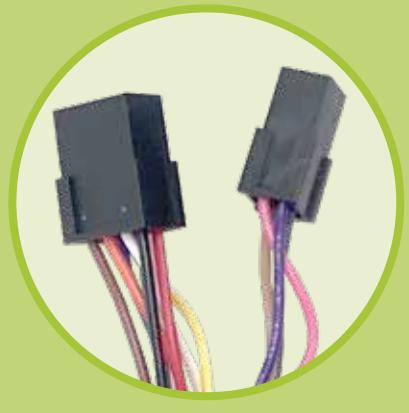
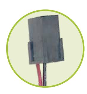
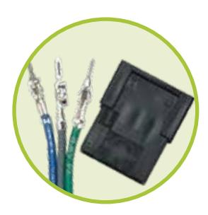
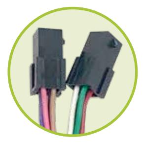
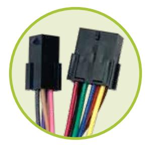
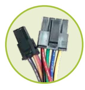
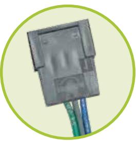
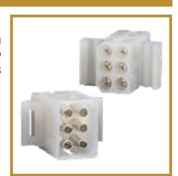
QUICK CONNECT CABLES
QC-CAB SERIES
INSTALLATION/TECH SPECS
Provides a pre-wired, plug-in connector that simplifies linking power to electrified product.
QUICK CONNECT CABLE ASSEMBLIES
QC-CAB-001
22/12 Dual Cable Connecting Cable for Motor Electric Latch Retraction 44" Length
QC-CAB-002
22/12 Frame to Ceiling Connecting Cable for Motor Electric Latch Retraction 180" Length
QC-CAB-003
22/2 Door Side Connecting Cable for Signal Switch Field Wire 36" Length
QC-CAB-004
22/3 Wire Switch Only Door Side Connecting Cable for Signal Switch Shipped with 3 Wires 10" Length
QC-CAB-005
22/12 Dual Cable Connecting for SM500 Electric Strike/Mullion Application 52" Length
QC-CAB-006
22/12 Frame to Ceiling Connecting Cable for FC500 Electric Strike/Mullion Application 52" Length
QC-CAB-007
22/8 Door Side Connecting Cable for EPT and EMT Pre-Wire 52" Length
QC-CAB-008
22/3 Door Side PAC-Wire Signal Switch 18" Length
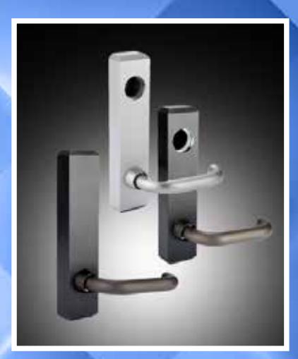
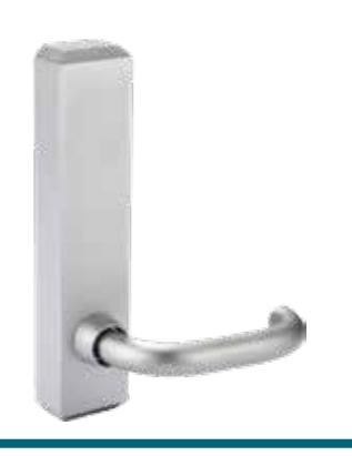
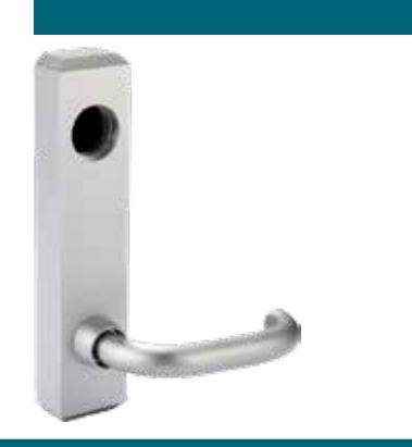
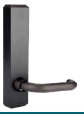
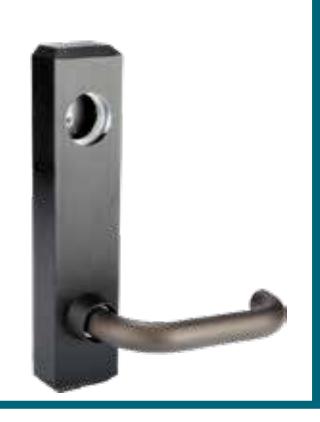
INSTALLATION/TECH SPECS
Easy and quick to install; Universal Mounting Prep; Steel Core Construction; Door Stiles as Narrow as 2"
L3 SERIES CVR LEVER TRIM
APPLICATIONS
Areas with need to for restricted/ monitored access such as:
- Schools
- Nursery's
- Hospitals
- Government Buildings, etc.
DOOR/ or OTHER SIZES
- The L3 lever trim's standard mounting hardware is suitable for 13 /4" thick doors
- For other door thicknesses please call 800-793-4544
PRODUCT MATERIALS
- Anodized Aluminum Lever
- Ergonomically Round Handle with reinforced steel interior lever body and mechanism.
SHIPPING
• FOB Our Dock; Shipping Weight with Standard Option – 4#
PART NUMBERING
L3A/B-C/D
SAMPLE NUMBER
L3710-M1CL
OPTIONS
(A) DEVICE TYPE
6 = CVR
7 = Rim Latch
(B) HAND
10 = LHRB
20 = RHRB
13 = LHRB w/cylinder
23 = RHRB w/cylinder
(C) FUNCTION
M0 = Inactive
M1 = Night Latch
M2 = Passage
M3 = Hold Down
E1 = Electric
(D) FINISH
CL = Clear
BR = Dark Bronze
CONDENSED SPECIFICATION
- The L3 Series Lever Trims shall be designed to be used with our 3600 & 3700 Series Exit Devices.
- Lever trim shall be a First Choice Building Products Series L3 suitable for mounting on door stiles as narrow as 2" and provided in anodized finishes on all exposed surfaces.
- The lever handle shall be round with reinforced stud attachment to the lever body.
- Lever shall have available options for passage, controlled or electronic function.
- (E1) Electronic Function requires low voltage (24vDC) and low amperage (.5 amp) power supply.
- The lever shall provide for universal mounting pattern independent of exit device function or handing.

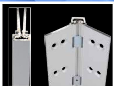
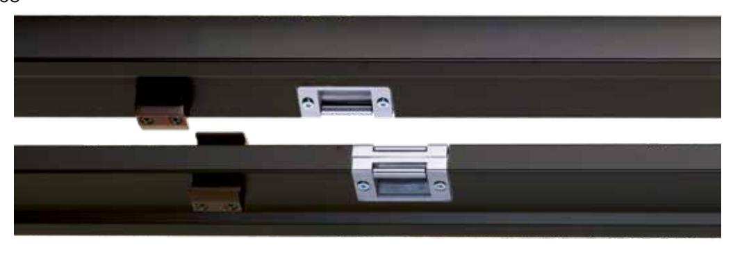
REMOVABLE MULLION
RM370 SERIES
INSTALLATION/TECH SPECS
Cast Aluminum Brackets; Steel Internal Stiffening Rod; Stainless Steel Strikes
PART NUMBERING
RM370-A/B/C
SAMPLE NUMBER
RM370-8CL-01010
OPTIONS
(A) SIZE 7 = 84" (C) STRIKE & CLIP Please Specify Options
8 = 96" 9 = 108" 01010 = Strike Preps with Security Clips and Clip Prep (Standard)
(B) FINISH 20010 = No Strikes or Strike Prep
CL = Clear BR = Dark Bronze 20200 = No Strikes or Strike Prep & No Security Clips or Clip Prep
BL = Black
The following preps enable installation of a surface of a surface mounted electric strike. The exit device mounting location will have to be modified to provide proper clearance.
Single side Prep for Electric Srike (No Strike)
Handing Required:
31010 L = Left hand Swing Out 41010 R = Right Hand Swing Out
51010 = Dual Slide Prep for Electric Strike (No Strike)
Single side Prep for Electric Strike (w/One Strike)
Handing Required:
61010 L = Left hand Swing Out 71010 R = Right Hand Swing Out
81010 = Dual Slide Prep for Electric Strike
APPLICATIONS
- Used with rim latching exit devices to provide a secure latching location
- Used with vertical rod devices to seal the gap between pairs of doors
DOOR/ or OTHER SIZES
- Door Heights up from 86" up to 110" Standard
- Custom Sizes Available
DIMENSIONS
• 31 /2" Thick, 1" Width at door contact point extending to 15 /8" in rear
PRODUCT MATERIALS
- Steel-reinforced aluminum
- Steel internal stiffening rod
- Cast aluminum brackets heavy duty stainless steel strikes
SHIPPING
• FOB Our Dock; Shipping Weight with Standard Option – 23-29#
CONDENSED SPECIFICATION
- Security Mullion shall be First Choice Building Products Series RM370 model utilizing steel-reinforced aluminum with a 1" dimension at door contact point
- The Mullion shall use an internal steel stiffening rod
- The Mullion shall use color matched stabilizer clips to provide an added level of security overcoming the natural twisting of the door stile under pressure
- The RM370 Series Mullions are field trimmable (for assistance call 800-793-4544)
- Check with door manufacturer for specific locating and frame preparation details

KRM370 SERIES
KEYED REMOVABLE MULLION
Keyed for quick and easy removal to provide the full width opening on a pair of doors
APPLICATIONS
• For secure installation of RM370 Mullion with quick removal capability
SHIPPING
• FOB Our Dock; Shipping Weight 3#
CONDENSED SPECIFICATION
- Security Mullion shall be First Choice Building Products Series KRM370 model utilizing steel-reinforced aluminum with a 1" dimension at door contact point
- The Mullion shall use an internal steel stiffening rod
- The Mullion shall use color matched stabilizer clips to provide an added level of security overcoming the natural twisting of the door stile under pressure
- The Mullion shall use heavy duty stainless strikes
- The KRM370 shall utilize a standard mortise key cylinder to provide quick removal of the Mullion in a secure and controlled manner
WARRANTY (See page 23 for complete warranty information)
PART NUMBERING
KRM370-CL KRM370-BR
OPTIONS
(A) FINISH
CL = Clear
BR = Dark Bronze
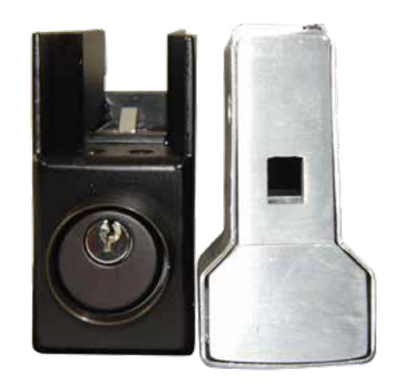

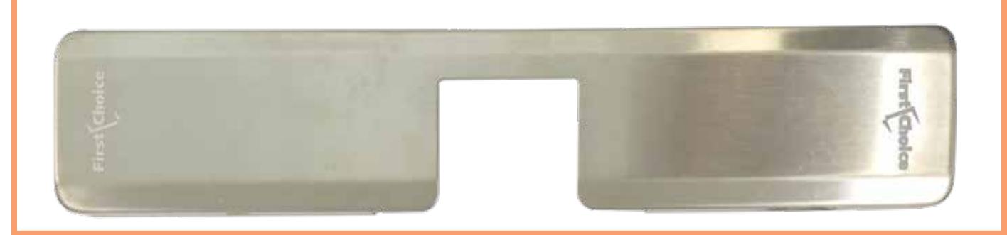
SURFACE MOUNT ELECTRIC STRIKE
SM500 SERIES
Grade 1 fire rated surface mount Rim Strike for pullman latches offer the very best strike quality and performance accommodating 1/2" to 3/4"
PART NUMBERING
SM500
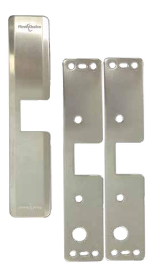
APPLICATIONS
Compatible with most exit devices. Includes cover and 2 spacer plates with horizontal adjustment to insure correct latch alignment in all applications.
OPTIONS
Available pre-wired with 8 pin Molex® Plug-in connectors.
PRODUCT MATERIALS
Temper resistant brushed stainless steel construction.
SHIPPING
• FOB Our Dock; Shipping Weight 2.6#
CONDENSED SPECIFICATION
- SM500 shall be Surface mounted, low profile 1/2"
- Shall provide Fail Safe/Fail Secure operation
- Shall have Static strength 1,500 lbs./Dynamic strength 70 ft.- lbs
- Single solenoid design shall provide superior strike reliability
- Shall supply Voltage 12/24V AC/DC
- Shall Draw 280mA@ 12V DC/140mA@ 24DC

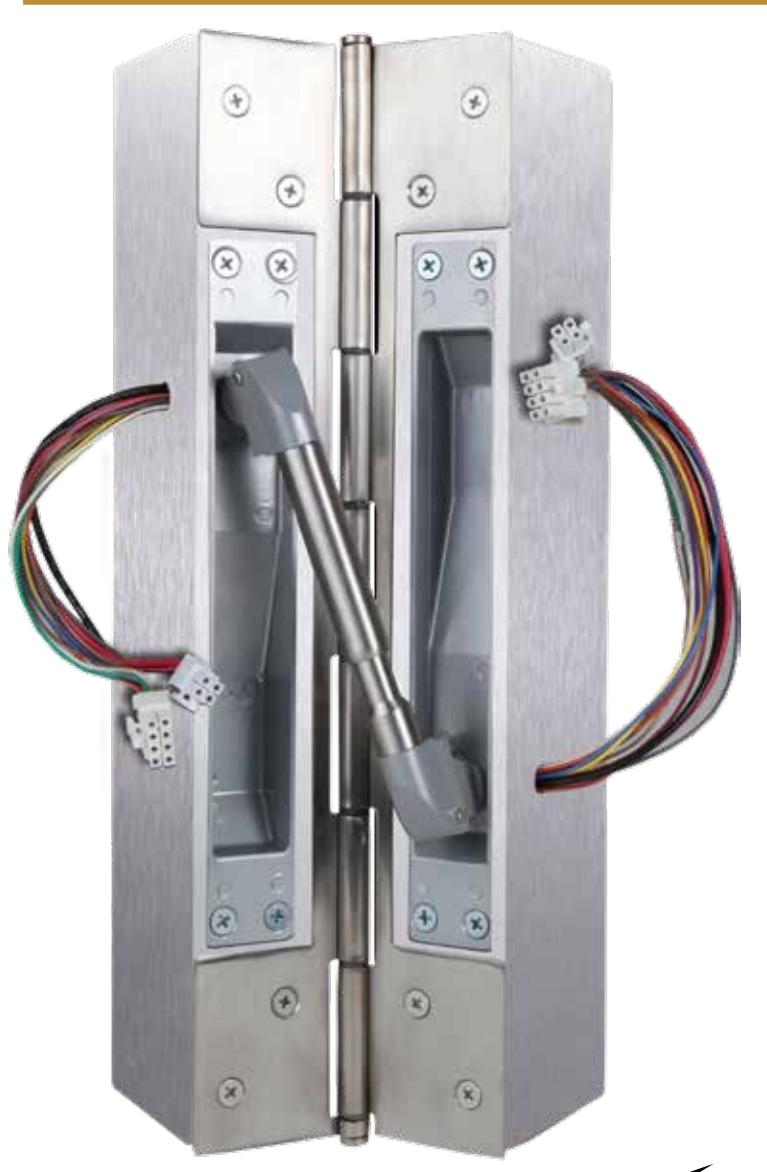
EPT3100 SERIES
CONCEALED RIGID POWER TRANSFER MORTISE MOUNT
Available with Molex® Connectors
Provides means of transferring electrical power or data from the frame to the door in a secure and discreet manner.
PART NUMBERING
EPT3100-A
SAMPLE NUMBER EPT3100-CL
OPTIONS
(A) FINISH
CL = Clear
BR = Dark Bronze
BL = Black
APPLICATIONS
For use on 13/4" thick doors. Conceals up to ten 24 AWG wires with a maximum rating of 24VDC, 1 Amp. Unit mortises into the edges of the door frame and is completely concealed when the door is in the closed position. Ideal for high abuse or heavy traffic situations.
OPTIONS
Available pre-wired with 8 pin Molex® Plug-in connectors.
PRODUCT MATERIALS
All metal construction including back boxes - NO PLASTIC PARTS.
SHIPPING
FOB Our Dock; Shipping Weight 3#

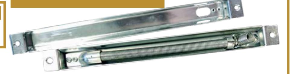
CONCEALED POWER TRANSFER
PART NUMBERING
EPT300
EPT300 SERIES
INSTALLATION/TECH SPECS
To be mortised into door frame in order to provide a concealed option to protect wires and cable connected to a First Choice electric latch retraction capable exit device.
APPLICATIONS
Used for electrified latch retraction devices in order to protect the wires attached to the First Choice Exit Device.
DOOR/ or OTHER SIZES
Fits any door size.
PRODUCT MATERIALS
All metal construction including back boxes - NO PLASTIC PARTS.
SHIPPING
• FOB Our Dock; Shipping Weight with Standard Options – 1#.
CONDENSED SPECIFICATION
- Device shall be First Choice Building Products Series EPT300 concealed mounted power transfer
- This device shall be made from stainless steel to be mortised into the door frame providing a protected wire run for bringing power to the First Choice Building Products exit device.
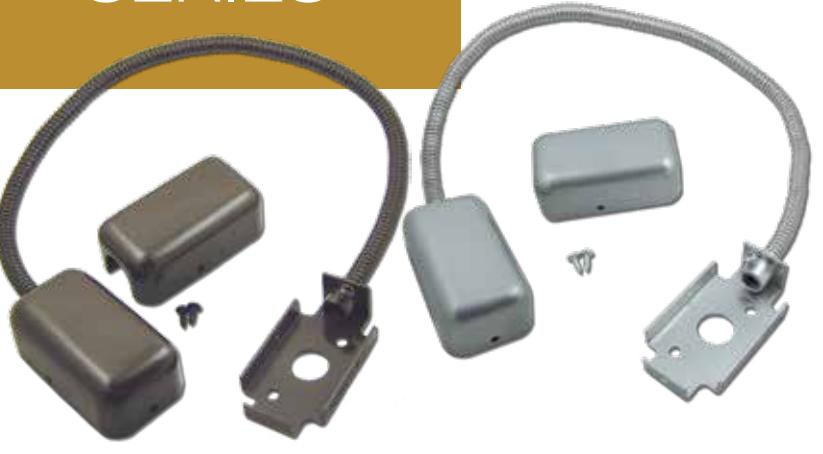
SURFACE MOUNTED POWER TRANSFERS
PART NUMBERING
EMT300-A
SAMPLE NUMBER EMT300-BR
OPTIONS
(A) FINISH
CL = Clear
BR = Dark Bronze
BL = Black
EMT300 SERIES
INSTALLATION/TECH SPECS
Surface mounted to both door and frame with matching dress caps
APPLICATIONS
Used for electrified latch retraction devices in order to protect the wires attached to the First Choice Exit Device
DOOR/ or OTHER SIZES
Fits any door size.
PRODUCT MATERIALS
Hardened aluminum armored cable with hardened aluminum base for attachment to door frame.
SHIPPING
• FOB Our Dock; Shipping Weight with Standard Options – 1#.
CONDENSED SPECIFICATION
- Device shall be First Choice Building Products Series EMT300 concealed mounted power transfer
- This device shall be made from hardened aluminum to be used for providing a protected wire run for bringing power to the First Choice Building Products exit device.

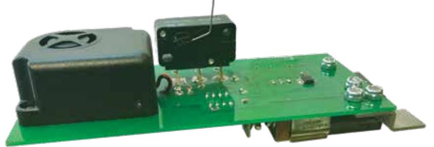
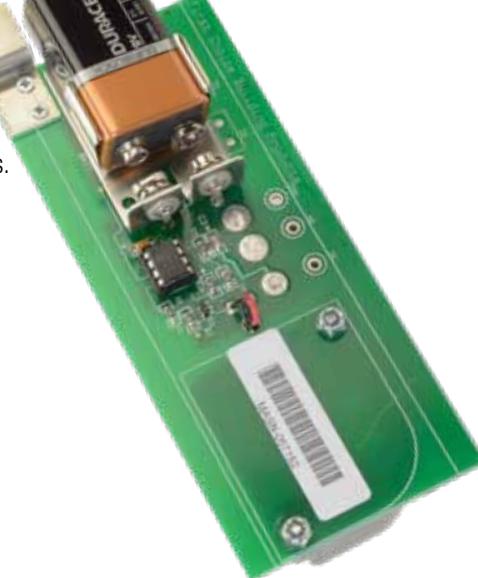
AL36 SERIES
ALARM KIT

Board Mounted Alarm with 9V Battery; Inserts into Standard Push Bar; Trigger Activated with Auto Reset
APPLICATIONS
Areas requiring monitored exit or alarm for security reasons such as:
- Schools, Hospitals
- Nursing Homes
- Stock Rooms
- Office Buildings, etc.
DOOR/ or OTHER SIZES
Fits all standard size 3690 & 3790 devices that have not been field trimmed.
DIMENSIONS
• 2" x 1" Alarm Control Board
PRODUCT MATERIALS
- Micro processor controlled, 105 Db horn
- Steel arm trigger and heavy duty micro-switch
SHIPPING
• FOB Our Dock; Shipping Weight with Standard Options – 1#
PART NUMBERING
AL36
Retrofit Kit fits any stock size First Choice 3600 or 3700 Series Device. Also available pre-integration into an exit device.
CONDENSED SPECIFICATION
- The Alarm Control Kits shall be designed to operate with the 3600 & 3700 Series Exit Devices.
- The mechanism shall be designed for the rigorous requirements of exit hardware.
- Powerful alarm shall emit a piercing notification of unauthorized egress to protect persons & property.
- Automatic resetting means the door shall remain protected at all times.
- The sophisticated circuitry of Alarm Kits shall provide up to 18 months of standby power or 500 alarm cycles from a standard 9V battery.
- Battery monitoring shall be constant and a "low charge" signal is provided to make it easy to maintain.
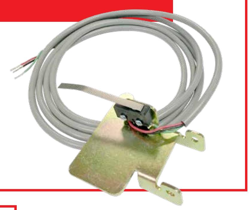
BRACKET MOUNTED SIGNAL SWITCH
INSTALLATION/TECH SPECS
Bracket Mounted Signal Switch; Normally Open/Normally Closed Wiring; Mounts within all First Choice Exit Devices.
SW300-2CA SERIES
PART NUMBERING
SW300-2CA
APPLICATIONS
- Provides a contact circuit monitoring push bar position.
- Field selectable normally open or normally closed.
DOOR/ or OTHER SIZES
- Ideal for devices equipped with MEL or AL options.
- Fits any size First Choice Building Products Series Devices.
SHIPPING
• FOB Our Dock; Shipping Weight with Standard Options – 1#
CONDENSED SPECIFICATION
- Signal switch shall be First Choice Building Products Series SW300-2CA Bracket Mounted Signal Switch.
- Device will provide a contact circuit monitoring push bar position.
- Device shall work with any First Choice Building Products Series Exit Devices.

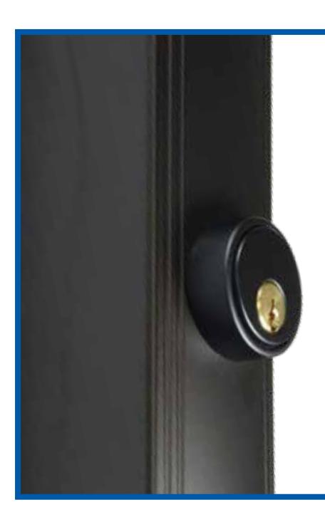
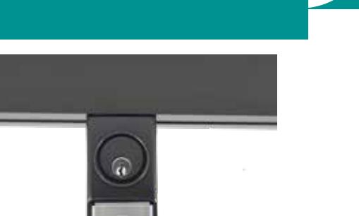
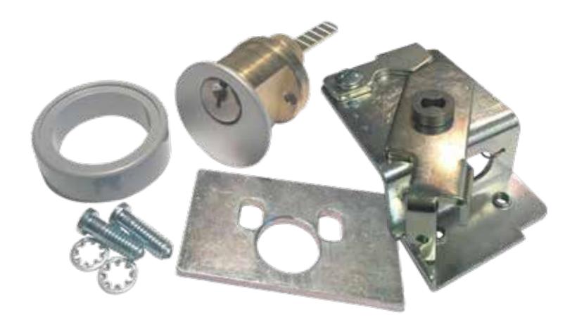
CD3000 SERIES
CYLINDER DOGGING KIT
INSTALLATION/TECH SPECS
Fits any standard size First Choice Building Products 3600 or 3700 Series Device. Replaces the original hex key dogging with key cylinder dogging. Assembly includes an aesthetically pleasing key cylinder collar for added security.
When preinstalled in an exit device or installed as a retrofit kit the key cylinder can easily be changed if need be for security or other purposes.
PART NUMBERING
CD3000-A
SAMPLE NUMBER
CD3000-BR
OPTIONS
(A) FINISH
CL = Clear
BR = Dark Bronze
APPLICATIONS
Areas requiring added security as to who can dog and undog the exit device. Uses any standard size rim type key cylinder.
OPTIONS
Comes with premachined push bar with hole cut for key cylinder for convenient installation. Available as retrofit kit: CD3000UK (fits any standard size First Choice 3600 & 3700 Series Device). Also available preintegrated into an exit device.
DIMENSIONS
.5" wide x .5" long
SHIPPING
FOB Our Dock; Shipping Weight Standard 36" with Standard Option – 11.4#
CONDENSED SPECIFICATION
- Device shall be an CD3000 upgrade kit to be used for providing 1/4 turn interior cylinder dogging for a First Choice Building Products Exit Device.
- The CD3000 Kit consists of a steel cylinder dogging assembly, an aluminum key cylinder collar, and a steel key cylinder retaining plate.

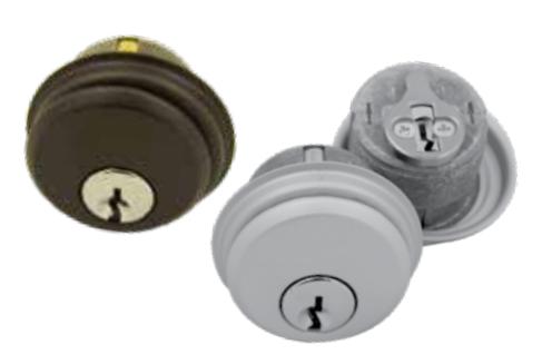
CYLINDER SERIES
RIM TYPE KEY CYLINDER
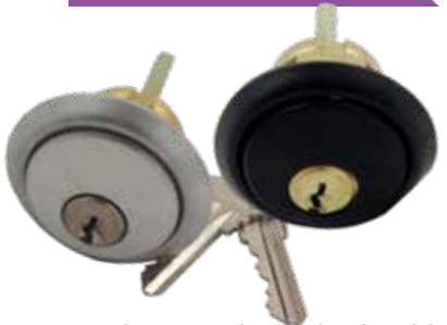
INSTALLATION/TECH SPECS
Horizontal or vertical tailpiece installation. 5 pin standard, drilled for 6 pin applications.
PART NUMBERING
841-AA
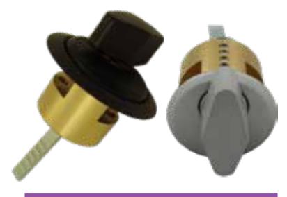
THUMB TURN RIM TYPE CYLINDER
INSTALLATION/TECH SPECS
Horizontal or vertical tailpiece installation. 5 pin standard, drilled for 6 pin applications.
PART NUMBERING
841-T-AA
MORTISE TYPE KEY CYLINDER
INSTALLATION/TECH SPECS
3/4" Length, 5 pin standard
PART NUMBERING
M100-AA
APPLICATIONS
- The 841 is a standard rim type cylinder.
- It is intended for use as an external key cylinder with 3600 or 3700 Series Exit Device with interior cylinder dogging.
APPLICATIONS
- The 841-T is a standard rim type cylinder with a thumb turn.
- It is intended for use as an external key cylinder with 3600 or 3700 Series Exit Device with interior cylinder dogging.
APPLICATIONS
- The M100 is a standard mortise type cylinder.
- It is intended for use L3 Series Lever Trim.
OPTIONS
(AA) FINISH
CL = Clear BR = Dark Bronze
PRODUCT MATERIALS
- Machined from solid brass or aluminum.
- Furnished with trim ring, mounting plate and break-off screws.
DIMENSIONS
• 23 /8" Tailpiece on Rim Type
SHIPPING
FOB Our Dock; Shipping Weight with Standard Options-1#

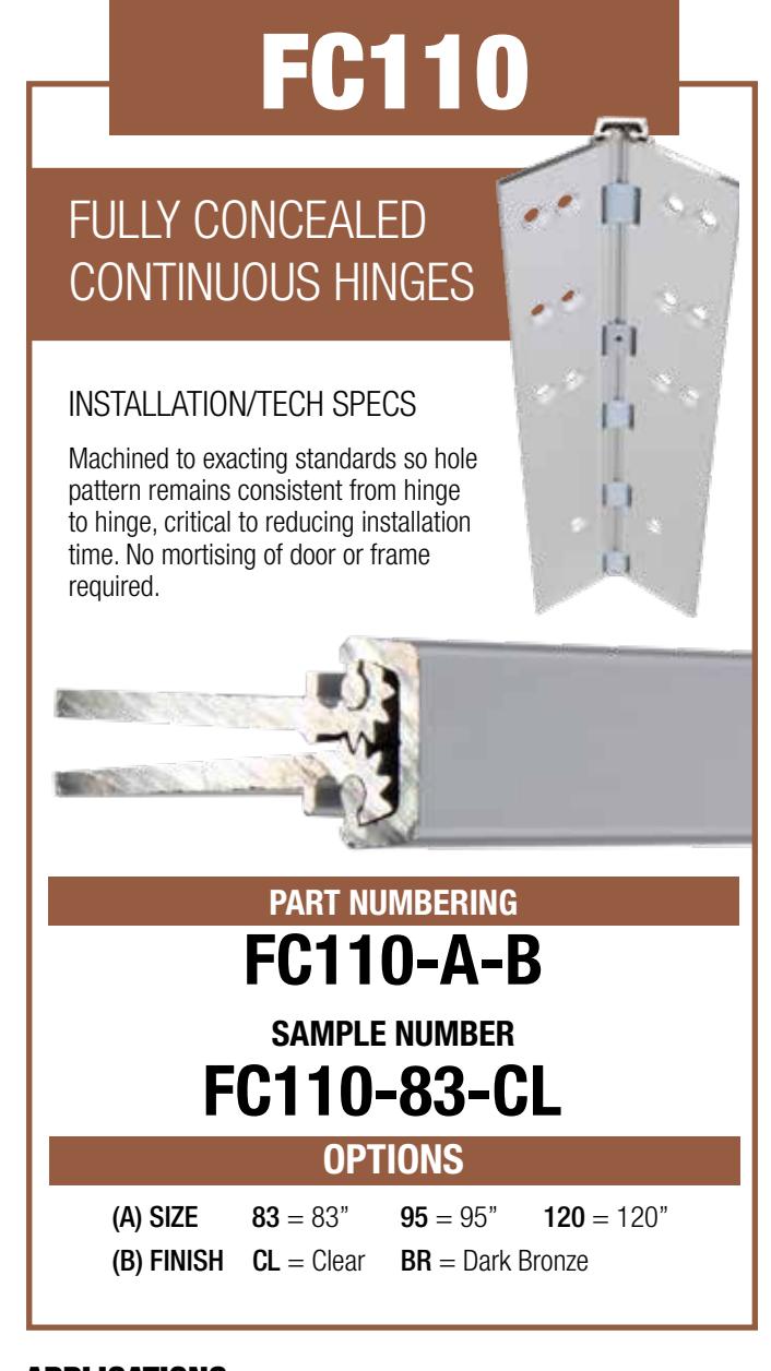
APPLICATIONS
For new installation or replacement of existing hardware
DOOR/ or OTHER SIZES
For doors up to 450 lbs.
DIMENSIONS
Available from 83" to 120"
PRODUCT MATERIALS
Extruded 6063 - T6 Aluminum Alloy with Polyacetal Thrust Bearings
SHIPPING
FOB Our Dock; Shipping Weight with Standard Options-8# For 83" Hinge 9# For 95" Hinge 11# For 120" Hinge
SHORT SPECIFICATION
- Hinge shall be First Choice Building Products Series FC110 Fully Concealed, Flush Continuous Hinge.
- This device shall be made from extruded 6063 T6 Aluminum Allow with polyacetal thrust bearings.
(B) FINISH CL = Clear
For new installation or replacement of existing hardware
BR = Dark Bronze
DOOR/ or OTHER SIZES
For doors up to 450 lbs.
DIMENSIONS
APPLICATIONS
Available from 83" to 120"
PRODUCT MATERIALS
Extruded 6063 - T6 Aluminum Alloy with Polyacetal Thrust Bearings
SHIPPING
FOB Our Dock; Shipping Weight with Standard Options-8# For 83" Hinge 9# For 95" Hinge 11# For 120" Hinge
SHORT SPECIFICATION
- Hinge shall be First Choice Building Products Series FC111 Fully Concealed, 1/8" Inset, Continuous Hinge.
- This device shall be made from extruded 6063 T6 Aluminum Allow with polyacetal thrust bearings.

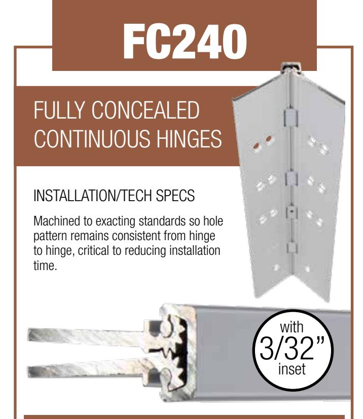
PART NUMBERING
FC240-A-B
SAMPLE NUMBER FC240-83-CL
OPTIONS
(A) SIZE 83 = 83" 95 = 95" 120 = 120" (B) FINISH CL = Clear BR = Dark Bronze
APPLICATIONS
For new installation or replacement of existing hardware
DOOR/ or OTHER SIZES
For doors up to 450 lbs.
DIMENSIONS
Available from 83" to 120"
PRODUCT MATERIALS
Extruded 6063 - T6 Aluminum Alloy with Polyacetal Thrust Bearings
SHIPPING
FOB Our Dock; Shipping Weight with Standard Options-8# For 83" Hinge 9# For 95" Hinge 11# For 120" Hinge
SHORT SPECIFICATION
- Hinge shall be First Choice Building Products Series FC240 Fully Concealed, 3/32" Inset, Continuous Hinge.
- This device shall be made from extruded 6063 T6 Aluminum Allow with polyacetal thrust bearings.
FC530
HALF SURFACE CONTINUOUS HINGES
INSTALLATION/TECH SPECS
Machined to exacting standards so hole pattern remains consistent from hinge to hinge, critical to reducing installation time.
PART NUMBERING
FC530-A-B
SAMPLE NUMBER
FC530-83-CL
OPTIONS
(A) SIZE 83 = 83" 95 = 95" 120 = 120"
(B) FINISH CL = Clear BR = Dark Bronze
APPLICATIONS
For new installation or replacement of existing hardware
DOOR/ or OTHER SIZES
For doors up to 450 lbs.
DIMENSIONS
Available from 83" to 120"
PRODUCT MATERIALS
Extruded 6063 - T6 Aluminum Alloy with Polyacetal Thrust Bearings
SHIPPING
FOB Our Dock; Shipping Weight with Standard Options-8# For 83" Hinge 10# For 95" Hinge 12# For 120" Hinge
SHORT SPECIFICATION
- Hinge shall be First Choice Building Products Series FC530 Half Surface Continuous Hinge.
- This device shall be made from extruded 6063 T6 Aluminum Allow with polyacetal thrust bearings.

FC570
FULL SURFACE CONTINUOUS HINGES
INSTALLATION/TECH SPECS
Machined to exacting standards so hole pattern remains consistent from hinge to hinge, critical to reducing installation time.
PART NUMBERING
FC570-A-B
SAMPLE NUMBER
FC570-83-CLO
OPTIONS
(A) SIZE 83 = 83" 95 = 95" 120 = 120"
(B) FINISH CL = Clear BR = Dark Bronze
APPLICATIONS
For new installation or replacement of existing hardware
DOOR/ or OTHER SIZES
For doors up to 450 lbs.
DIMENSIONS
Available from 83" to 120"
PRODUCT MATERIALS
Extruded 6063 - T6 Aluminum Alloy with Polyacetal Thrust Bearings
SHIPPING
FOB Our Dock; Shipping Weight with Standard Options-10# For 83" Hinge 12# For 95" Hinge 14# For 120" Hinge
SHORT SPECIFICATION
- Hinge shall be First Choice Building Products Series FC570 Full Surface Continuous Hinge.
- This device shall be made from extruded 6063 T6 Aluminum Allow with polyacetal thrust bearings.

WARRANTY
First Choice warrants that products manufactured by us will be free of defects in material and workmanship for a period of Two Years from date of invoice. The Purchaser shall be obligated to promptly report any failure of conformance with this warranty, in writing, to First Choice within the warranty period whereupon First Choice shall, at its option, correct such non-conformity, by repair or replacement, provided the Purchaser has installed, maintained and operated such product in accordance with good industry practices and has complied with the recommendations of First Choice. First Choice shall not be liable for any repairs, replacements, or adjustments to the product or any costs of labor performed by the Purchaser or others without First Choice's prior written approval.
First Choice makes no other warranty or representation of any kind whatsoever, expressed or implied, except that of title, and all other implied warranties of merchantability and fitness for a particular purpose, are hereby disclaimed.
FAQs
What Does This Warranty Cover?
We warrant all of our products against defects in either material or workmanship.
What Does This Warranty Not Cover?
We do not warrant against errors in installation or application, nor are we liable for consequential damages.
What is the Period of Coverage?
We will cover our products for a period of two years from the date of our original shipment.
What Will We Do to Correct Problems?
We will decide to either repair or replace the products to provide what we determine is the best solution to the problem
What Will We Not Do?
We will not provide coverage for labor or transportation charges without prior written agreement.
How Do You Get Service?
You only have to report any product failure or non-conformance directly to us within the warranty period.
What Must You Do to Keep the Warranty in Effect?
You need only maintain the devices with periodic inspection and maintenance.
Are There Any Express or Implied Warranties?
There are no warranties, express or implied, except those stated above.

NOTES
| _ | ||
|---|---|---|