FCBP PSEL3000-2 Dual Device Power Supply (for Solenoid) Installation Manual
Open the original PDF document
View PDF

PSEL3000-2 2 Electric Panic Device Power Controller (16 Amps)
Installation Guide

Table of Contents:
| Overview 3 |
|---|
| Specifications 3 |
|
Installation Instructions
3-4 PSEL3000-2 |
| Maintenance4,5 |
|
LED Diagnostics
4 PSEL3000-2 |
|
PSEL3000-2
Terminal Identification 5 |
| Wiring Distance Table 6 |
| Enclosure Dimensions 8 |
Overview:
PSEL3000-2 will operate up to two (2) 24VDC panic hardware devices simultaneously. It is designed to handle the high current surge panic hardware locking devices demand. Each lock output has an adjustable relock delay timer. It will con-trol a pair of doors simultaneously or independently control two individual doors. It has a follower relay for each output to trigger external relays, ADA push plate switches, etc. Delayed follower relays control automatic door operators for doors that are always locked or for doors that are unlocked during the business day. In addition, two un-switched auxiliary volt-age outputs are provided for powering card readers, keypads, REX PIRs, electronic timers, relays, etc. A programmable FACP interface will either provide power or remove power to the lock outputs when activated. LED status indicators are provided to monitor AC power, FACP status and for lock output wiring supervision. Intelligent logic provides protection against accidental shorting of lock outputs.
Specifications:
Agency Approval:
- UL Listed for Access Control System Units (UL 294).
- CSFM California State Fire Marshal Approved.
- MEA NYC Department of Buildings Approved.
Input:
- Input 115VAC 50/60Hz, 3.5 amp.
- Two (2) N.O. trigger inputs.
Outputs:
- Two (2) 24VDC individually controlled lock outputs rated @ 16 amp for 300ms, .75 amp continuous supply current.*
-
One (1) 24VDC filtered regulated auxiliary output rated @ 1 amp continuous supply current* (Not affected by FACP trigger).
- *Note: Total combined current for the 24VDC outputs may not exceed 1.75 amps.
- One (1) 12VDC filtered regulated auxiliary output rated @ 1 amp continuous supply current (Not affected by FACP trigger).
- Two (2) follower form "C" relay outputs rated @ 1 amp/28VDC. Relays energize while input is closed.
- Two (2) delayed follower form "C" relay outputs rated @ 1 amp/28VDC. Delay time is selectable .5 seconds or 1 second. Energized duration is 1 second.
Battery Backup:
- Built-in charger for sealed lead acid or gel type batteries.
- Automatic switch over to stand-by battery when AC fails.
- Maximum charge current .3 amp.
Battery Backup (cont'd.):
• When 7AH batteries are used, battery capacity for emergency stand-by is at least 1 hour.
Visual Indicators:
- Green AC input LED indicates 115VAC present.
- Green input LEDs indicate panic device status/trouble. (activated, short or open circuit)
- Red FAI LED indicates FACP disconnect is activated.
Fire Alarm Disconnect:
- Normally Closed FACP trigger input.
-
Programmable Fire Alarm Disconnect options:
- Removes power to outputs and disables delayed follower relays.
- Connects power to lock outputs and enables delayed follower relays.
Additional Features:
- Adjustable panic release from 1 sec. to 30 secs. Note: The outputs will turn off upon hold time expiration as set per delay trim pots or input release if the later is longer than hold time.
- Cam lock included.
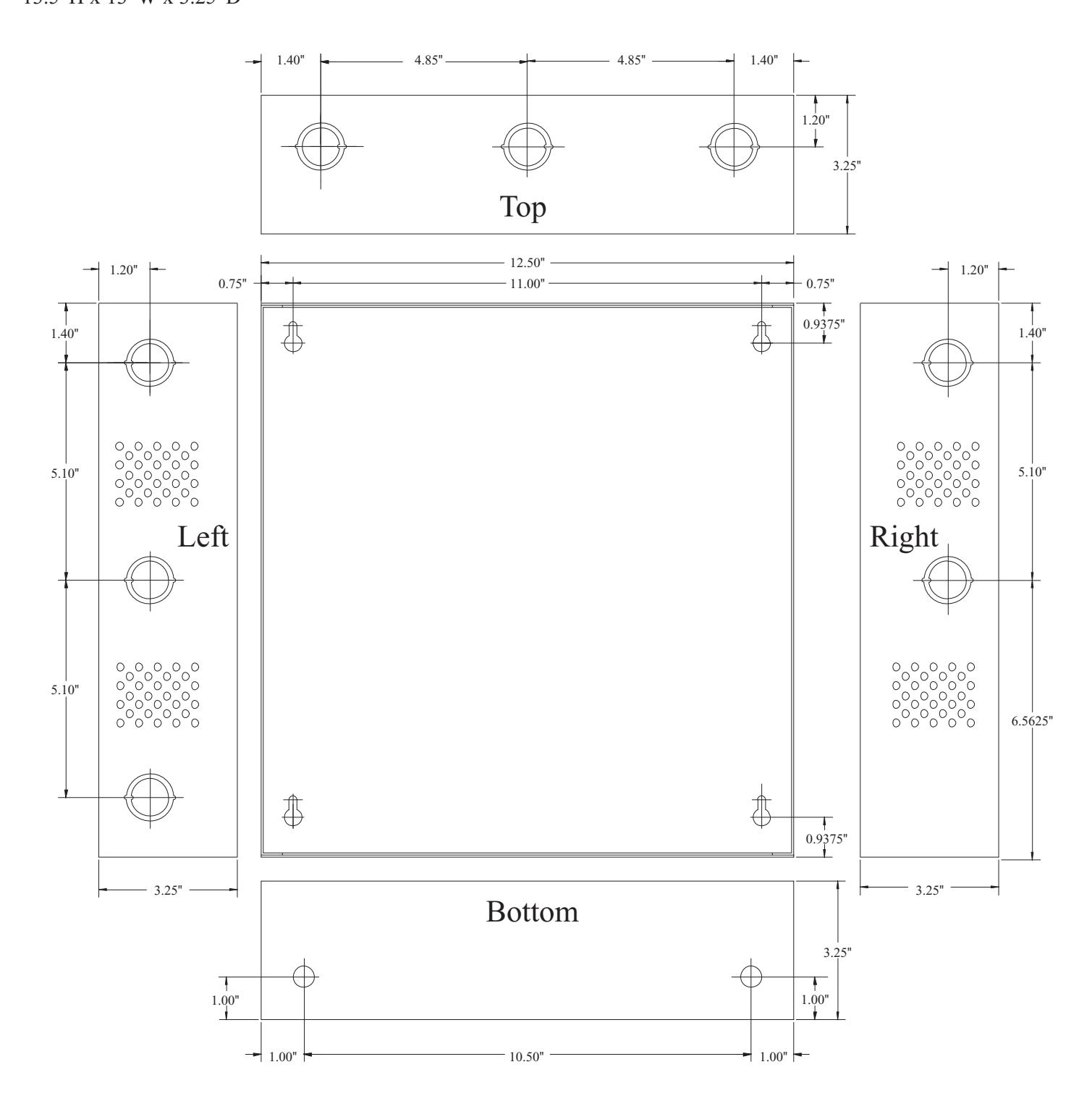
Enclosure Dimensions:
13.5"H x 13"W x 3.25"D
PSEL3000-2 Installation Instructions:
Wiring methods shall be in accordance with the National Electrical Code/NFPA 70/NFPA 72/ANSI, and with all local codes and authorities having jurisdiction. Product is intended for indoor use only.
- 1. Mount unit in desired location within protected premises (Maximum Wiring Distance, pg. 6). Mark and predrill holes in the wall to line up with the top two keyholes in the enclosure. Install two upper fasteners and screws in the wall with the screw heads protruding. Place the enclosure's upper keyholes over the two upper screws, level and secure. Mark the position of the lower two holes. Remove the enclosure. Drill the lower holes and install the two fasteners. Place the enclosure's upper keyholes over the two upper screws. Install the two lower screws and make sure to tighten all screws (Enclosure Dimensions, pg. 8) . Secure cabinet to earth ground.
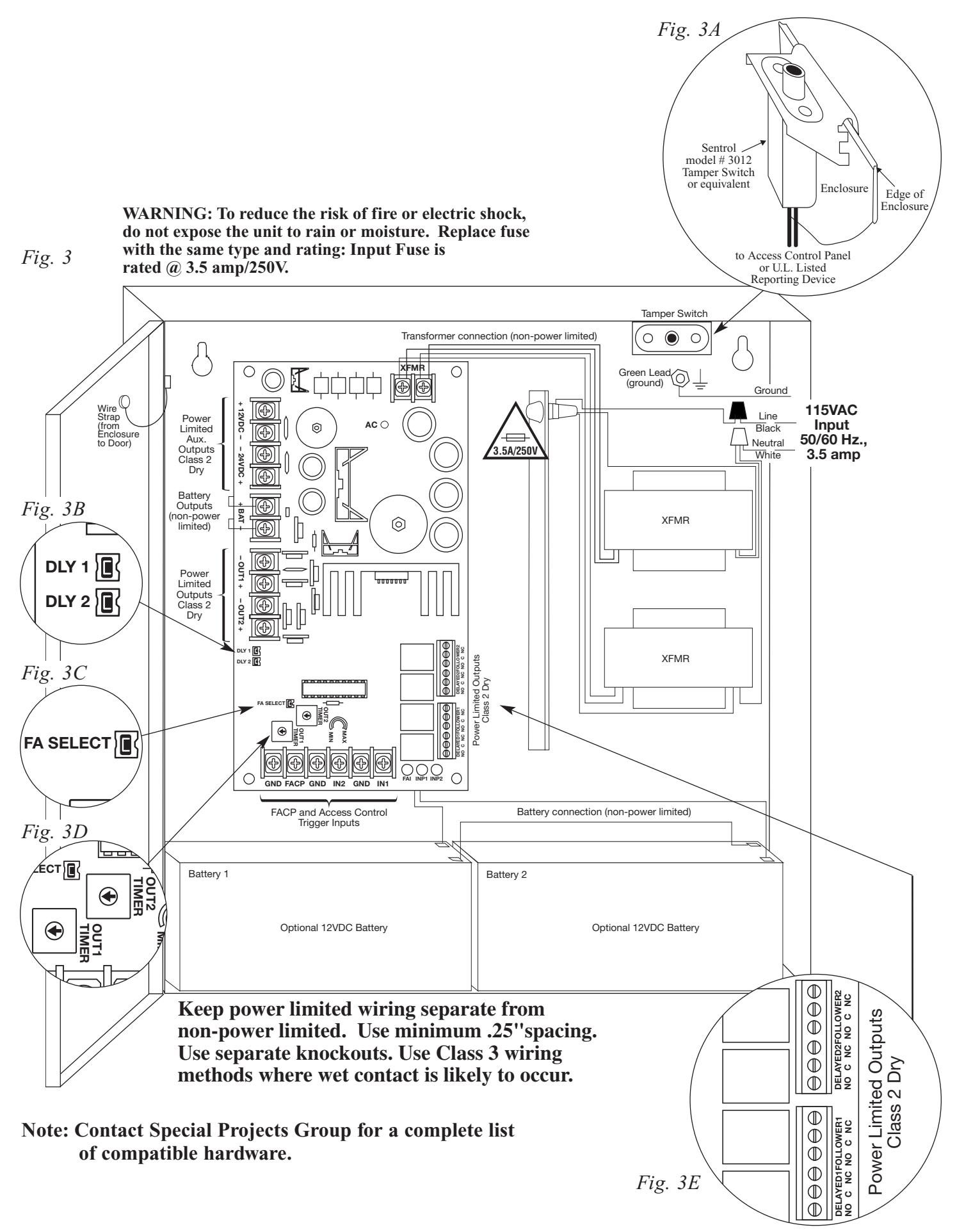
- 2. Connect AC power (115VAC 50/60Hz) black (line) and white (neutral) flying leads (Fig. 3, pg. 7).
- 3. Measure output voltage before connecting devices. This helps avoid potential damage.
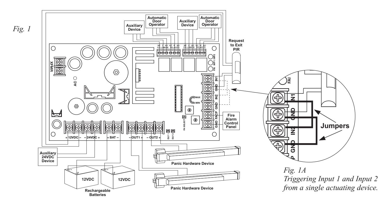
- 4. Connect panic hardware device # 1 to terminals marked [+ OUT1 -- ], connect panic hardware device # 2 to terminals marked [+ OUT2 -- ] (Fig. 1, pg. 5) . Be sure to observe polarity.
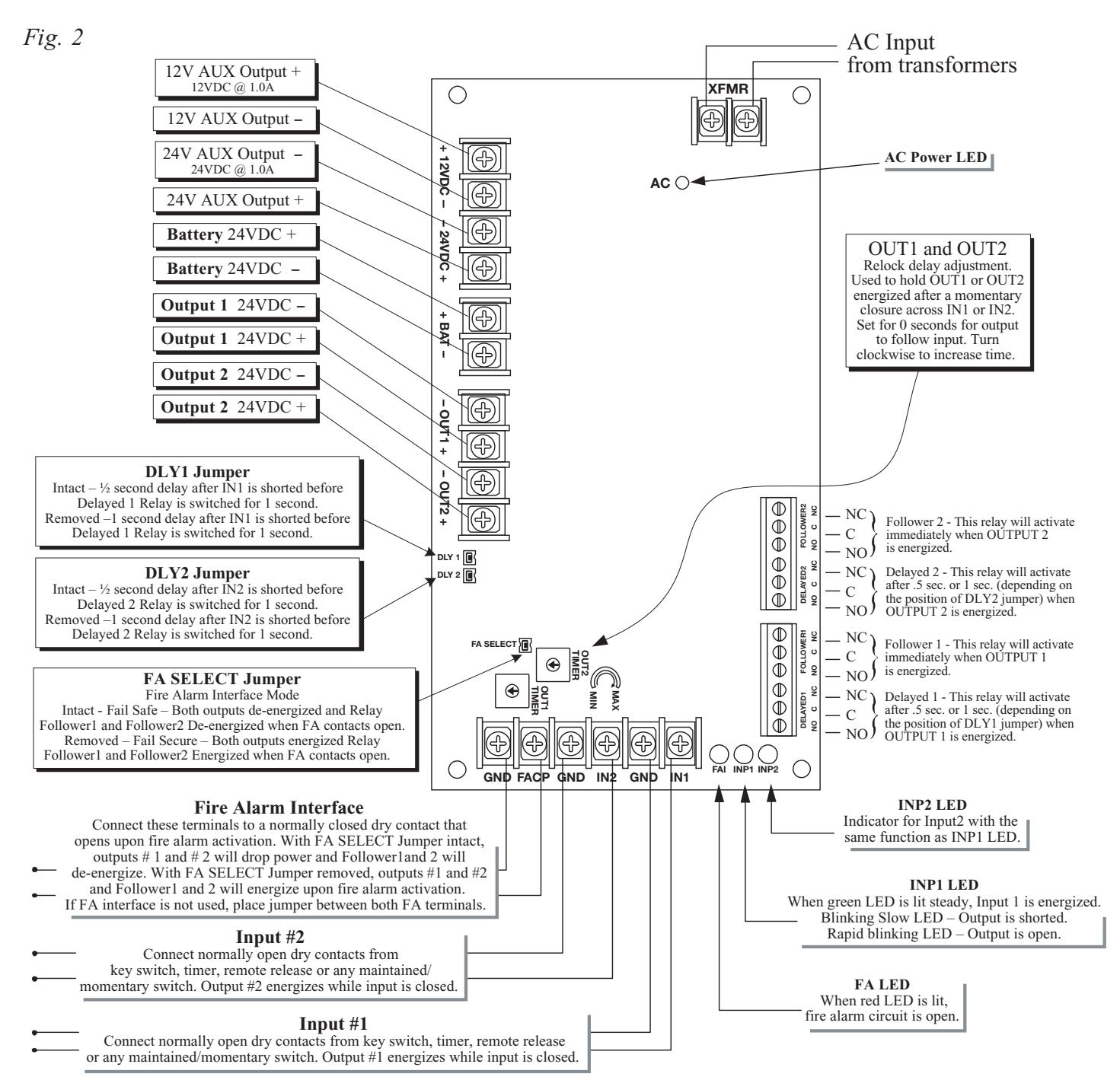
- 5. Set lock output release time by adjusting [OUT1] and [OUT2] potentiometers. Turn potentiometer clockwise to increase time or counter clockwise to decrease time. Timing range is 300ms to 30 seconds, (unit is factory set @ 300ms) (Fig. 3D, pg. 7) .
Note: When external control of door unlock time is desired, i.e., card reader, set time to minimum (completely counter-clockwise).
PSEL3000-2 - 3 -
6. Connect Normally Open (NO) Dry Contacts from actuating devices such as an Access Control Panel, REX PIR, Keypad, etc. to terminals marked [GND, IN1] and [GND, IN2] (Fig. 1A, pg. 5) . Note: If it is desired to trigger both Input 1 and Input 2 from a single actuating device, install jumpers between
terminals marked [IN1] and [IN2] and also both terminals marked [GND] (Fig. 1A, pg. 5) .
- 7. Connect auxiliary devices to be powered (Keypads, REX motion detectors, electronic timers, external relays ) to the appropriate auxiliary power output terminals. For 12VDC devices, use terminals marked [+ 12VDC -- ]. For 24VDC devices, use terminals marked [-- 24VDC +] (Fig. 1, pg. 5) .
- 8. Connect devices to be controlled to terminals marked [DELAYED1, DELAYED2] and/or [FOLLOWER1, FOLLOWER2] (Dry form "C" contacts are rated @ 1 amp/28VDC) (Fig. 1, pg. 5) . Adjust delay time using jumper pins marked [DLY1] and [DLY2] (Fig. 3B, pg. 7) (0.5 seconds with jumper in place, one (1) second with jumper removed), (unit is factory set for 0.5 seconds delay).
Note: All interconnecting devices must be UL Listed when the installation requires UL compliance.
9. To hookup the Fire Alarm Disconnect feature, wire the normally closed (NC) output from a Fire Alarm Control Panel to the terminals marked [FACP] and [GND] of PSEL3000-2.
The "FA Select" jumper provides two (2) modes of operation (Fig. 3C, pg. 7) :
- A) With the jumper in place, the application of a FACP trigger input (open circuit) while Input 1 and Input 2 are triggered will cause the unlocked (energized) panic hardware devices to relock (de-energize). Follower relays will release (de-energize).
- B) With the jumper removed, the application of a FACP trigger input (open circuit) while Input 1 and Input 2 are not triggered will cause the locked (de-energized) panic hardware devices to unlock (energize). Follower relays will activate (energize). Delayed relays will energize momentarily.
Note: With the jumper removed, the application of a FACP trigger input (open circuit) while Input 1 and Input 2 are triggered will have no affect on the operation of Output 1 or Output 2 and their corresponding Follower or Delayed relays.
- 10. When using stand-by batteries, they must be lead acid or gel type. 7AH batteries will provide one (1) hour backup time. Connect two (2) 12VDC batteries wired in series to the terminals marked [+ BAT --]. For Access Control applications batteries are optional. When batteries are not used loss of AC will result in the loss of output voltage.
- 11. Mount U.L. Listed tamper switch (Sentrol model 3012 or equivalent) at the top of the enclosure. Slide the tamper switch bracket onto the edge of the enclosure approximately 2" from the right side (Fig. 3A, pg. 7) . Connect tamper switch wiring to the Access Control Panel input or the appropriate U.L. Listed reporting device. To activate alarm signal open the door of the enclosure. Install tamper switch when required.
- 12. Upon completion of wiring secure enclosure door with screws or cam lock (supplied).
PSEL3000-2 LED Diagnostics:
| LED | LED Status | Panic Device Power Controller Status |
|---|---|---|
| AC Input - Green |
On
Off |
Normal operating condition.
Loss of AC. |
| INP1 - Green |
On
Slow Blink Rapid Blink Off |
Output 1 energized.
Output 1 open circuit. Output 1 short circuit. Output 1 De-energized. |
| INP2 - Green |
On
Slow Blink Rapid Blink Off |
Output 2 energized.
Output 2 open circuit. Output 2 short circuit. Output 2 De-energized. |
| FAI - Red |
On
Off |
FACP Input triggered (alarm condition).
FACP normal (non-alarm condition). |
Maintenance:
Unit should be tested at least once a year for the proper operation as follows:
FACP Supervision: To insure proper connection and operation of the Fire Alarm disconnect hookup, remove wire from the terminal marked [FACP] on PSEL3000-2. With the [FA Select] jumper removed, locked Panic Hardware Devices will unlock. With the [FA Select] jumper in place, unlocked Panic Hardware Devices will relock. When the wire is reconnected to the [FACP] terminal the Panic Hardware Devices will relock with the [FA Select] jumper removed or will unlock with the [FA Select] jumper in place.
- 4 - PSEL3000-2
Maintenance (cont.):
Output Voltage Test: Under normal load conditions the DC output voltage should be checked for proper voltage level. Battery Test: Under normal load conditions check that the battery is fully charged, check specified voltage both at battery terminal and at the board terminals marked [+ BAT -] to insure there is no break in the battery connection wires. Note: Maximum charging current under discharge is 300mA.
Note: Expected battery life is 5 years, however it is recommended changing batteries in 4 years or less if needed.
Caution: For continuous protection against risk of electric shock and fire hazard, replace input fuse with the same type and rating 3.5 amp/250V. Do not expose to rain or moisture, indoor use only.
PSEL3000-2 Terminal Identification:
| Terminal Legend | Function/Description | ||
|---|---|---|---|
| + 12VDC - | 12VDC Auxiliary Output @ 1 amp. | ||
| - 24VDC + | 24VDC Auxiliary Output @ 1 amp. | ||
| + BAT - | 24VDC Stand-by Battery Connection (Two (2) 12VDC batteries wired in series). | ||
| - OUT 1 + | Connect 24VDC Panic Hardware Device #1. | ||
| - OUT 2 + | Connect 24VDC Panic Hardware Device #2. | ||
| FACP / GND | Normally Closed Dry Contact from Fire Alarm Control. | ||
| IN1 / GND | N/O Trigger input controls Output 1. May be held closed for extended unlocking. | ||
| IN2 / GND | N/O Trigger input controls Output 2. May be held closed for extended unlocking. | ||
| Delayed 1 | Dry form "C" contacts provide a 1 second momentary pulse after a preset delay. With jumper [DLY1] in place the delay is 0.5 seconds. With jumper [DLY1] removed the delay is 1 second. This permits the Panic Hardware Device to fully unlock before signaling auto operator to swing door. | ||
| Delayed 2 | Dry form "C" contacts provide a 1 second momentary pulse after a preset delay. With jumper [DLY2] in place the delay is 0.5 seconds. With jumper [DLY2] removed the delay is 1 second. This permits the Panic Hardware Device to fully unlock before signaling auto operator to swing door. | ||
| Follower 1 | Dry form "C" contact. Energizes while output 1 is energized. Enables outside ADA switch plate to actuate auto operator while door is unlocked. De-activates outside ADA actuator while door is locked. | ||
| Follower 2 | Dry form "C" contact. Energizes while output 2 is energized. Enables outside ADA switch plate to actuate auto operator while door is unlocked. De-activates outside ADA actuator while door is locked. | ||
PSEL3000-2 -5-
Note: For independent operation of Output 1 and 2, connect NO dry contact between IN1 and GND and/or IN2 and GND. For sequential operation of OUT1 and OUT2 install a jumper between IN1 and IN2 and a jumper between both GND terminals.
Wiring Distance Table:
| InRush | Wire | Electric Butt or Pivot | ЕРТ |
|---|---|---|---|
| Current | Gauge | Max distance from Power Supply to frame side of opening | Max distance from Power Supply to frame side of opening |
| 8 amp | 14 AWG Stranded | 75 ft. | 100 ft. |
| 8 amp | 12 AWG Stranded | 175 ft. | 200 ft. |
| 12 amp | 14 AWG Stranded | 60 ft. | 75 ft. |
| 12 amp | 12 AWG Stranded | 80 ft. | 100 ft. |
| 16 amp | 14 AWG Stranded | 40 ft. | 75 ft. |
| 16 amp | 12 AWG Stranded | 60 ft. | 80 ft. |
| 16 amp | 10 AWG Stranded | 100 ft. | 125 ft. |
-6- PSEL3000-2
First Choice Building Products is not responsible for any typographical errors.