Excel Series E6200 Installation Instructions
Open the original PDF document
View PDF


801 Avenida Acaso, Camarillo, Ca. 93012 (805) 494-0622 • Fax: (805) 494-8861 www.sdcsecurity.com • E-mail: service@sdcsecurity.com
INSTALLATION INSTRUCTIONS E6200 SERIES MAGNETIC LOCK
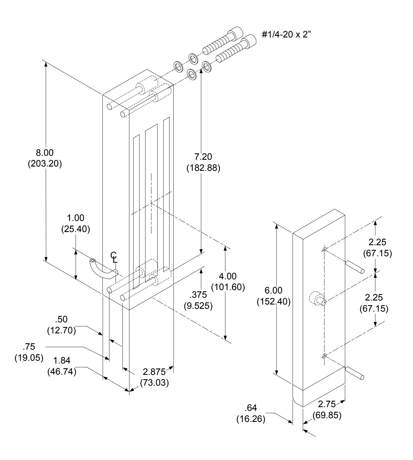
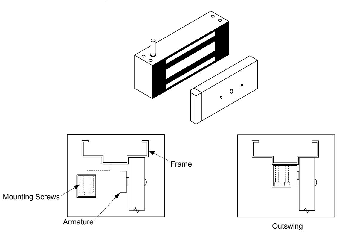
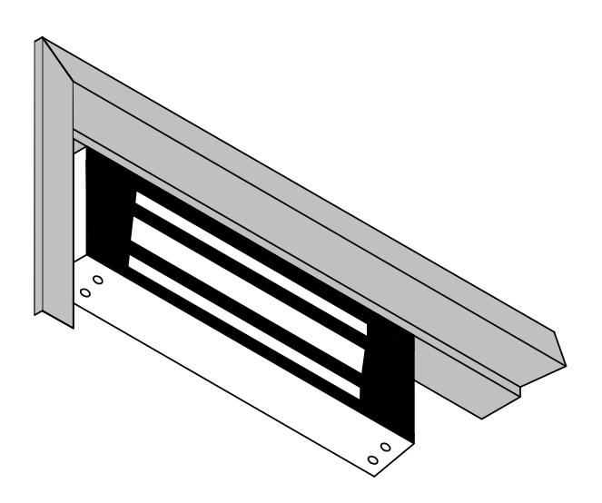
The E6200 Series magnetic lock is mounted to the underside of the header, on the stop side of the door.
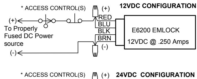
Electrical Instructions:
Use properly fused U. L. Listed Power Supply
Do not install a diode in parallel with any magnetic lock. A diode will cause a delay when releasing the door and residual magnetism to occur.
Although SDC recommends the use of a DC power supply, a transformer with an adjacent mounted full wave bridge rectifier may be used. A significant drop will occur when using a full wave bridge rectifier.
Any low voltage condition will cause erratic operation of the optional board sensor.
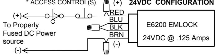
When using a full wave bridge rectifier all access controls and/or release contacts must be located between the EMlock and rectifier to ensure quick release.
Electrical Specifications:
Dual Voltage 12 or 24VDC
Power Consumption .250mA@12VDC
.125mA@24VDC
DS Door Status Sensor SPDT, 500mA@30VDC LS Lock Status Sensor SPDT, 2A@30VDC
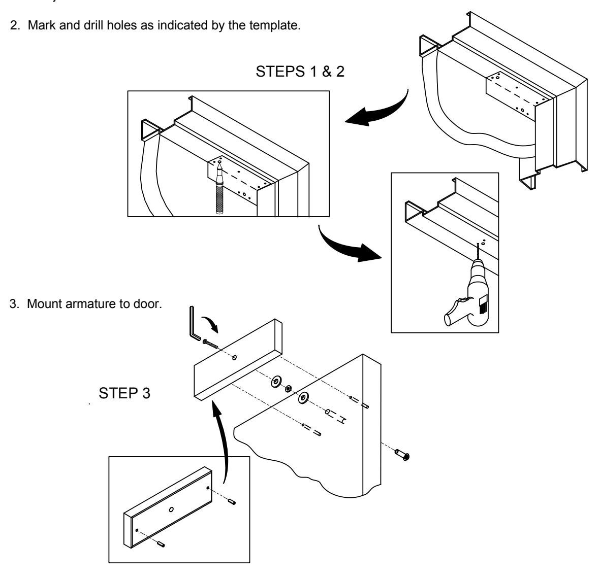
1. Fold template as indicated on dotted line. For single doors locate template against the door and header on the lock jamb side of the frame.
4. WIRING DETAILS:
BOND SENSOR (BAS) WIRING
|
WIRE
COLOR |
CONTACT | DESCRIPTION | |
| YEL | N/O | GOOD BOND | |
| GRN | COM | COMMON | |
| ORG | N/C | NO/POOR BOND | |
DOOR POSITION SENSOR (DPS) WIRING
|
WIRE
COLOR |
CONTACT | DESCRIPTION |
|---|---|---|
| WHT | N/O | ACTIVATE WHEN DOOR OPEN |
| GRY | COM | COMMON |
| VIO | N/C |
ACTIVATE WHEN DOOR
CLOSED |
5. Install magnet onto the header with the magnetic face towards the door side of the stop. Assure that the magnet and armature line up properly, then tighten down ALL mounting screws.
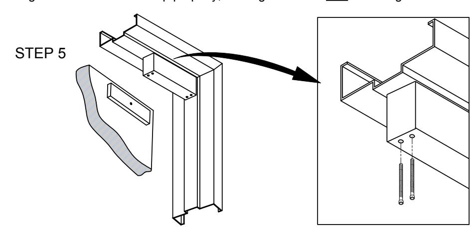
6. Test operation. When all is operating properly, install anti tamper plugs over socket head screws using a soft hammer to avoid damage to the housing.
MODEL E6200