Excel Series E600 Installation Instructions
Open the original PDF document
View PDF801 Avenida Acaso, Camarillo, Ca. 93012 (805) 494-0622 • Fax: (805) 494-8861 www.sdcsecurity.com • E-mail: service@sdcsecurity.com
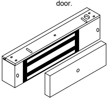
INSTALLATION INSTRUCTIONS E600 SERIES MAGNETIC LOCK
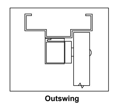
The E600 Series magnetic lock is mounted to the underside of the header, on the stop side of the door. An inswing mounting kit (optional) can be used when mounting on the hinge side of the
Electrical Instructions:
Use properly fused U. L. Listed Power Supply
Do not install a diode in parallel with any magnetic lock. A diode will cause a delay when releasing the door and residual magnetism to occur.
Although SDC recommends the use of a DC power supply, a transformer with an adjacent mounted full wave bridge rectifier may be used. A significant drop will occur when using a full wave bridge rectifier.
Any low voltage condition will cause erratic operation of the optional board sensor.
When using a full wave bridge rectifier all access controls and/or release contacts must be located between the magnetic lock and rectifier to ensure quick release.
Electrical Specifications:
Dual Voltage 12 or 24VDC
Power Consumption 500mA@12VDC
250mA@24VDC
DS Door Status Sensor SPDT, 500mA@30VDC LS Lock Status Sensor SPDT, 2A@30VDC


Any suggestions or comments to this instruction or product are welcome. Please contact us through our website or email engineer@sdcsecurity.com
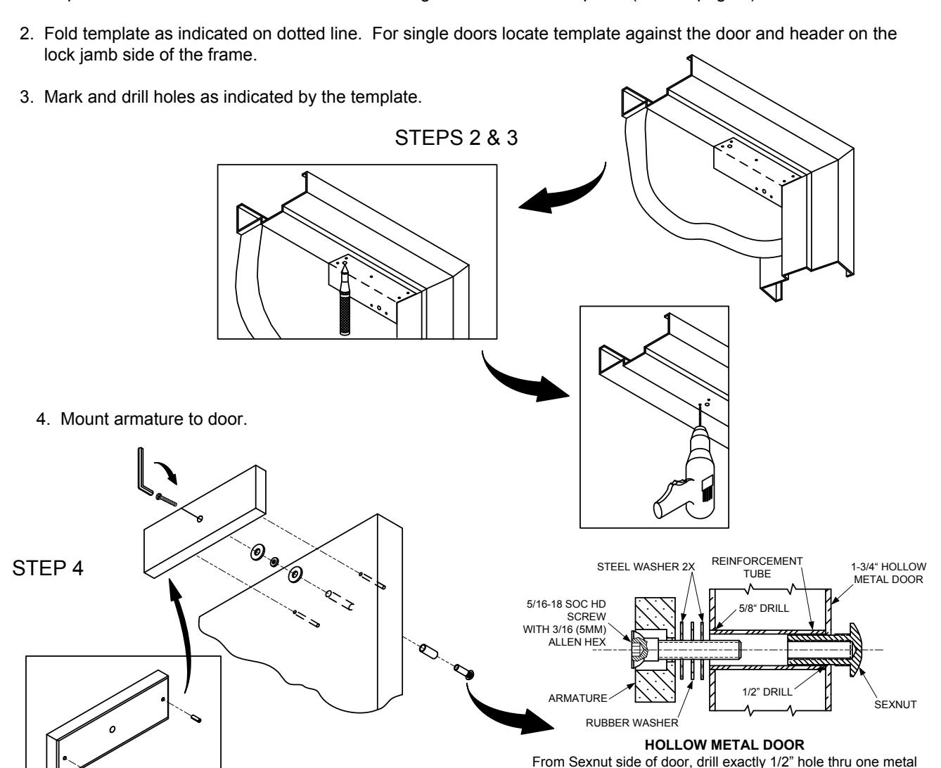
1. Inspect the frame header to determine if mounting accessories are required (refer to page 4).
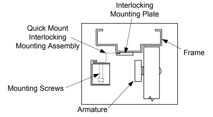
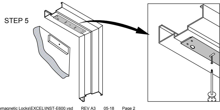
5. Install mounting plate to header with the interlock detail away from the door side of the stop. Loosely fasten screws through adjustment slot as shown. Assure that the mounting plate and armature line up properly, then tighten down ALL mounting screws.
thickness only. From Armature side of door, drill 5/8" hole to insert reinforcement tube. Press in sexnut and reinforcement tube all the way and mount armature to door using hardware provided.
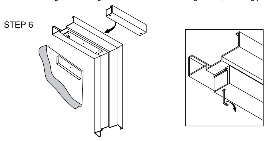
6. Holding the magnet housing at each end, engage the entire length of the interlock detail, by pushing towards the door. Tap with a soft hammer to ensure proper alignment and engagement.
CAUTION: The lock body must be held in place until secured with mounting screws. Secure socket head screws provided inside the housing at each end. Start screws into threads carefully to avoid stripping the threads. Check alignment and tighten screws. Pull wires through frame, mounting plate and magnet housing
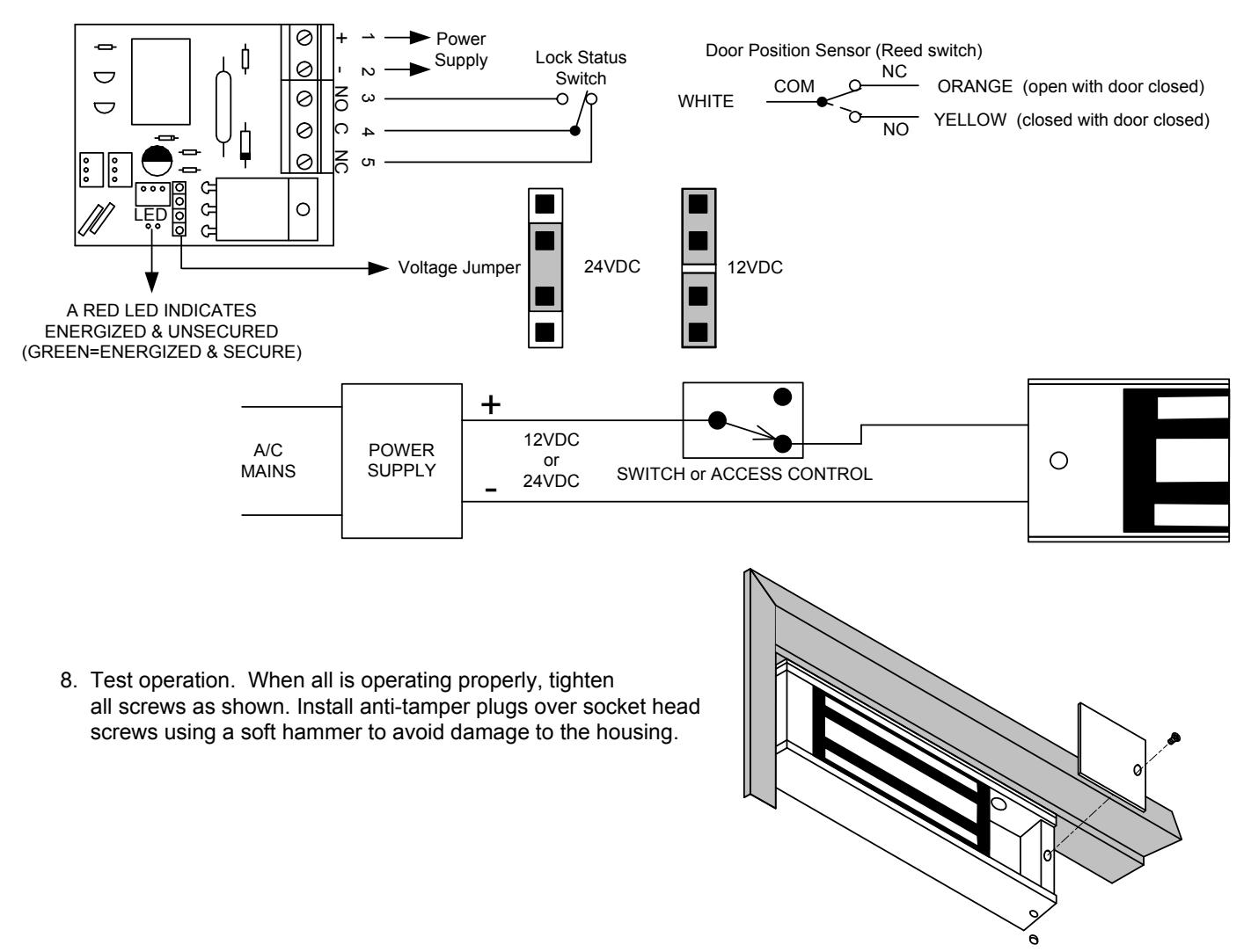
7. Select jumper position for 12VDC or 24VDC. Connect power to magnetic lock.
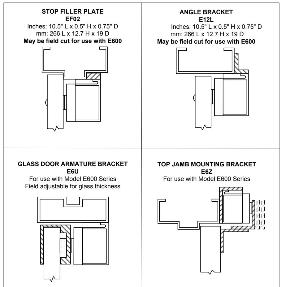
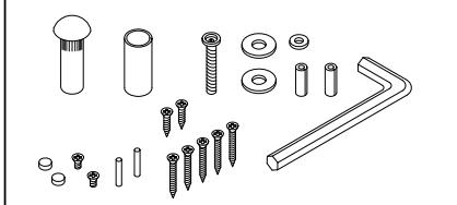
MOUNTING ACCESSORIES:
Supplied Mounting Hardware
To maintain surface plating from corrosion:
- Do not touch the lock face with your hands.
- Clean lock face with Scotch-Brite pad by 3M (do not use sandpaper).
- Apply a thin film of rust inhibitor (LPS-3) on lock face.
- Repeat application on armature plate.