End of Line Resistors for EcoFlex Electrified Mortise Locks and Integrated Wiegand (Harmony, SE LP10) Installation and Wiring Instructions
Open the original PDF document
View PDF

1. Description
The EcoFlex mortise lock platform, including SARGENT Harmony and SE LP10 Integrated Wired mortise locks, is now available with internal end-of-line resistors for comprehensive monitoring of the circuit between the access control panel and lock. Integrating the end-of-line resistors into the lock not only eliminates the risk of undetected tampering, but reduces installation costs, simplifies specification, and offers the assurance of a factory installed and tested product.
2. EAC Resistor Configurations (see reverse page for wiring diagrams)
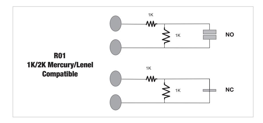
• R01: Mercury/Lenel Standard 1K/2K
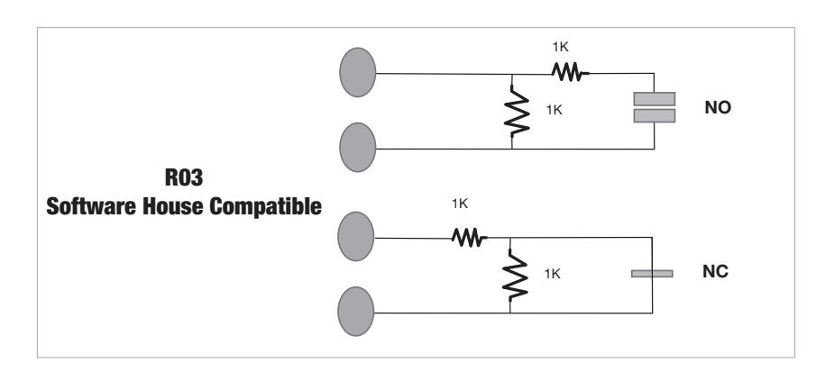
• R03: Software House Standard 1K/2K
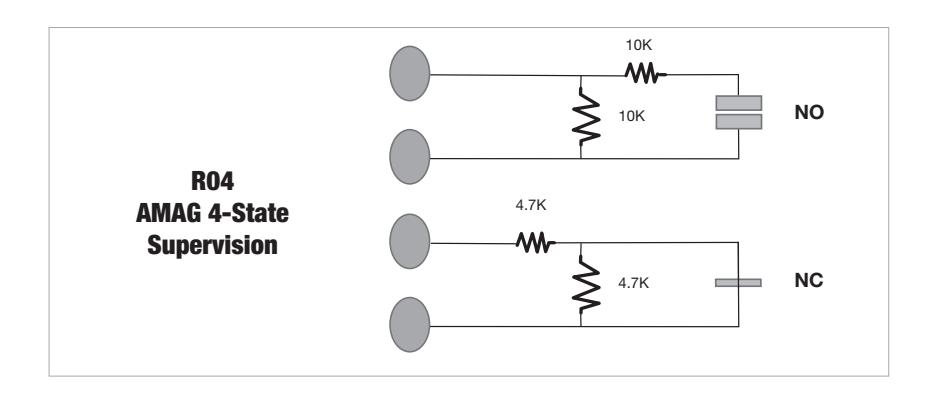
• R04: AMAG 4-State supervision
NOTE: End-of-Line Resistor harnesses are designated by blue shrink-tubing
| Tamper | Normal | Tamper | Normal | |||||||||
|---|---|---|---|---|---|---|---|---|---|---|---|---|
| ID | OEM | Description | REX | Short | Open | Secure | Alarm | DPS | Short | Open | Secure | Alarm |
| R01 | Mercury/Lenel | Standard 1K/2K | NO | 0Ω | ∞Ω | 2KΩ | 1KΩ | NC | 0Ω | ∞Ω | 1KΩ | 2KΩ |
| R03 | Software House | Standard 1K/2K | NO | 0Ω | ∞Ω | 1KΩ | 500Ω | NC | 0Ω | ∞Ω | 1KΩ | 2KΩ |
| R04 | AMAG | 4-State Supervision | NO | 0Ω | ∞Ω | 10KΩ | 5KΩ | NC | 0Ω | ∞Ω | 4.7KΩ | 9.4KΩ |
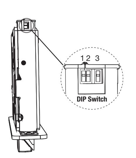
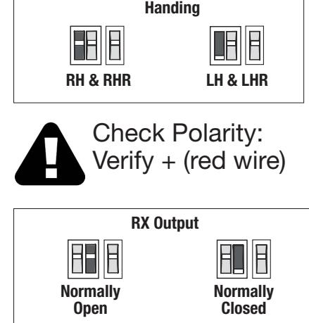
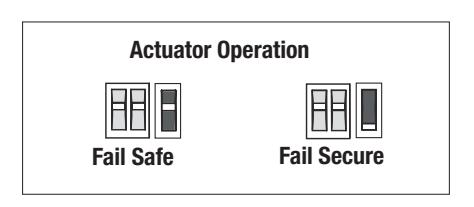
3. Configure DIP Switch Settings
IMPORTANT:
This product is built and factory tested to the configuration specified. Any change to the 3-position DIP-switch settings located at the bottom of the mortise lock body must be made prior to lock installation.

4. Wiring Diagrams
There are three primary resistor configurations available: