Emtek Touch™ Keypad Deadbolt Locksets Installation & Programming Guide
Open the original PDF document
View PDF

Installation & Programming Guide
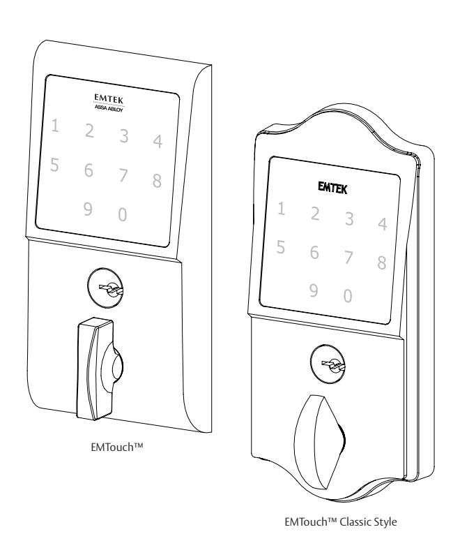
EMTouch™ & EMTouch™ Classic Style Electronic Deadbolt Locksets
4c 4d ITEM NO. DESCRIPTION QTY. Key 2 Outside Trim Plate Assembly 1 Deadbolt Latch Assembly 2 3/8" or 2 3/4" Backset 1 Inside Trim Plate Assembly 1 4a Inside Chassis 1 4b Inside Trim Plate 1 4c #8-32 x 3/8" Flat Head Machine Screw 2 4d 9V Alkaline Battery 1 #8-32 x 11/2" Flat Head Machine Screw 2 #8 x 3/4" Wood Screw 4 Strike Plate 1 Security Plate 1 #10 x 3" Wood Screw 2 4b 4a What's in the Box
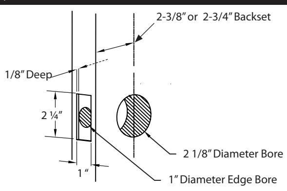
Preparation
1. Door Prep
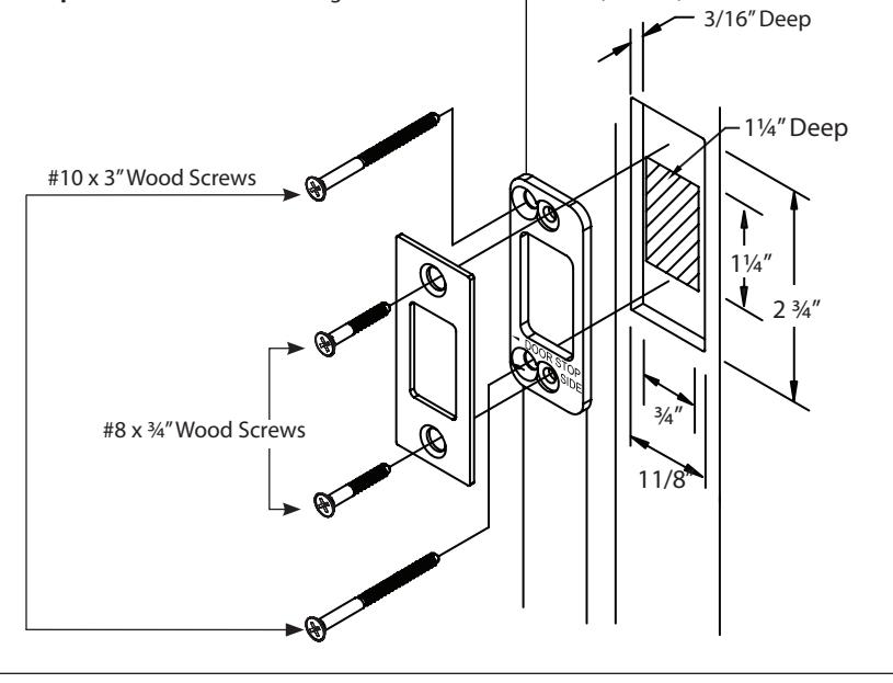
2. Door Jamb Prep
Step 1: Fasten Security Plate using two #10 x 3" Wood Screws (item #9).
Step 2: Fasten Strike Plate using two #8 x 3/4" Wood Screws (item #6).
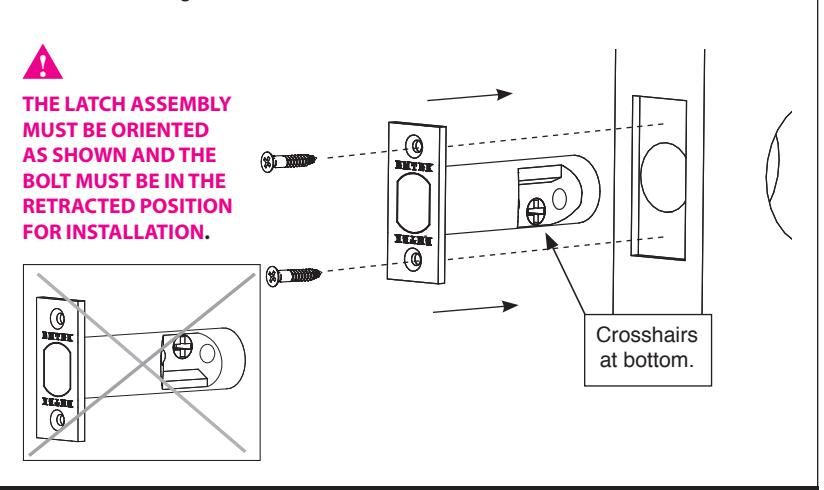
1. Install Latch
Fasten Latch using two #8 x 3/4" Wood Screws (item #6).
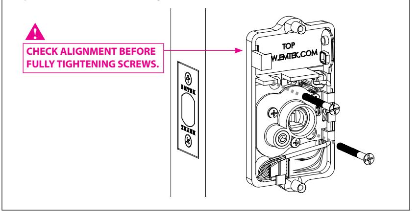
2. Remove Screws from Inside Trim Plate
Use a Phillips head screwdriver to remove screws (item #4c) shown below and detach Inside Trim Plate from the Inside Chassis.
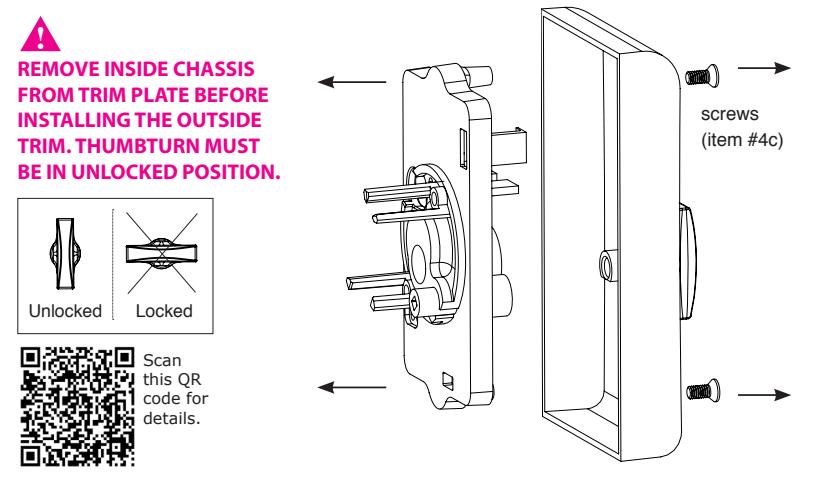
3. Install Outside Trim Plate Assembly
Position the Outside Trim Plate Assembly through the bore hole.

ONCE POSITIONED, OUTSIDE TRIM PLATE ASSEMBLY REQUIRES SUPPORT.

Scan this QR code for details.
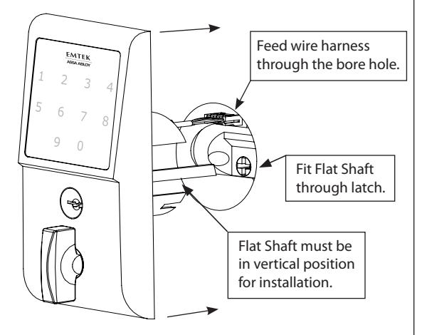
4. Install Inside Chassis
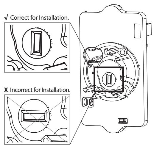
Step 1: Confirm the position of Flat Shaft.

HOLE FOR FLAT SHAFT MUST BE IN VERTICAL POSITION FOR INSTALLATION.
4. Install Inside Chassis
Step 2: Feed the Wire Harness through Inside Chassis.
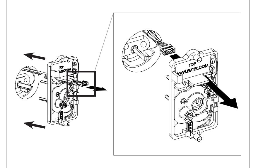
Step 3: Fasten Inside Chassis using two #8-32 x 11/2" Flat Head Machine Screws (item #5).
Step 4: Connect Wire Harness (A) and tuck Connectors as shown (B).
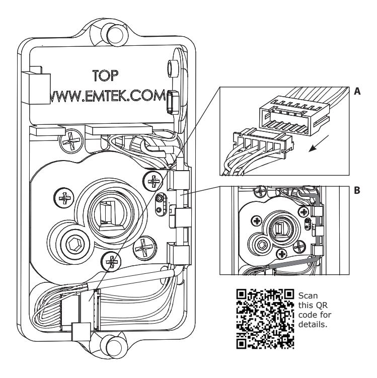
Step 5: Install Battery. For optimal performance, always use a good quality battery. 9V Battery
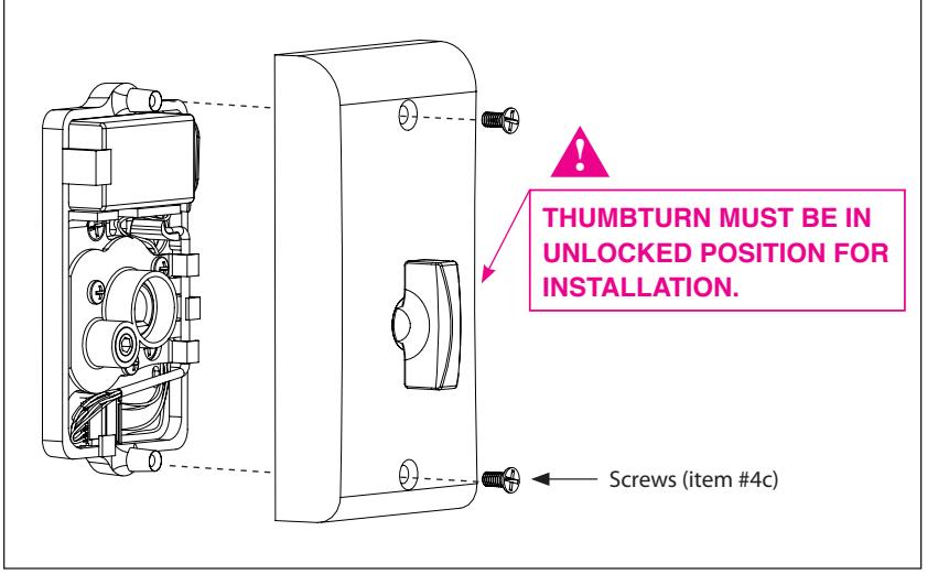
5. Install Inside Trim Plate
Fasten Inside Trim Plate using two #8-32 x 3/8" Flat Head Machine Screws (item #4c).
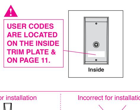
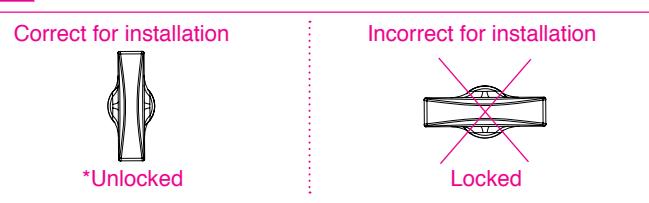
* Unlocked position is required for installation and removal of the Inside Trim Plate Assembly.
Your Lock is Ready to Use
Your Emtek lock is shipped with two 4-digit user codes and a 6-digit programming code. These codes are randomly generated at the factory. (Turn to next page for Programming Instructions.)
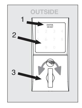
To Unlock:
- 1. Press EMTEK key or touch 3 fingers across screen.
- 2. Enter 4-digit user codes. (See sticker located on the inside trim plate or on page 11).
- 3. Rotate Thumbturn.
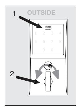
To Lock:
Option 1
- 1. Press EMTEK key.
- 2. Rotate Thumbturn.
Option 2
- 1. Touch 3 fingers across screen.
- 2. Enter 4-digit user codes. (See sticker located on the inside trim plate or on page 11).
- 3. Rotate Thumbturn.
Programming Your Lock
In order to perform each of the following six functions, the lock must first be placed in Programming Mode:
- 1. Press and hold EMTEK button for 3 seconds
- 2. Yellow LED flashes, then remains solid*, number keys also illuminate
- 3. Enter Programming Code
- 4. Yellow LED flashes, then 1 beep
- 5. Yellow LED remains solid (awaiting button press; see following Table)
|
If
you wish to |
Press
Button |
Actions |
Indica
tors |
|||
|---|---|---|---|---|---|---|
|
Change
Programming Code (6 digits) |
1 |
Enter New
Programming Code (6 digits) |
Re-Enter
New Programming Code (6 digits) |
• 1 Green LED flash
• 1 beep • 1 Green LED flash • 1 beep • 2 Green LED flashes • 2 beeps |
||
|
Add User Code
(4 digits) (Store up to 20 User Codes) |
2 |
Enter New
User Code (4 digits) |
Re-Enter
New User Code (4 digits) |
• 1 Green LED flash
• 1 beep • 1 Green LED flash • 1 beep • 2 Green LED flashes • 2 beeps |
||
| Delete User Code | 3 |
Enter User
Code to be Deleted |
Re-Enter
User Code to be Deleted |
• 1 Green LED flash
• 1 beep • 1 Green LED flash • 1 beep • 2 Green LED flashes • 2 beeps |
||
|
**Enable/Disable
All User Codes |
4 |
Entering '4' disables all Users
(enables all if disabled) |
• 2 Green LED flashes
• 2 beeps |
|||
|
Delete All User
Codes |
5 | Re-Enter Programming Code |
• 1 Green LED flash
• 1 beep • 2 Green LED flashes • 2 beeps |
|||
|
Turn Beeper On/
Off |
6 | Entering '6' turns OFF (or ON) |
• 1 Green LED flash
• 1 beep • 2 Green LED flashes • 2 beeps |
|||
* If no input within 20 seconds, Yellow LED goes out, Red LED flashes and lock exits Programming Mode.
** Also referred to as "vacation mode". This command temporarily disables all user codes (metal key override will still work).
Keypad Operation - Beeper & LED Indicators
| Function | Indicators | |||
|---|---|---|---|---|
| Valid Code |
• 1 short beep, EMTEK button flashes
Green. |
|||
| Invalid Code/Access Denied* |
• 1 Red LED flash
• 2 short beeps |
|||
| Lock-Out Mode Error |
• 2 short beeps
• 1 short beep per second for duration |
|||
| Access Accepted |
• 1 short beep
• 1 Green LED flash |
|||
| Low Battery |
• 4 Red LED flashes
• 4 short beeps |
|||
| Blackout Battery** |
• 1 long Red LED flash
• 4 long beeps |
|||
| Button Press Accepted |
• 1 Yellow LED flash
• 1 Short Beep |
|||
| Outside Thumb Turn Enabled | • 2 Green LED flashes | |||
* If 3 consecutive incorrect codes are entered, the lock emits 4 short beeps and a flashing Red EMTEK button. The lock will not accept additional input for 20 seconds (20 beeps). When the next valid code is entered the lock will beep quickly 5 times to alert of the incorrect codes.
Restoring the Lock to Factory Default Setting
This procedure clears the lock of all users and restores the Programming Code and 2 User Codes shipped with the lock.
- Press and hold EMTEK button for 3 seconds.
- Enter "000000"
- After 2 beeps and 2 Green LED Flash, remove power (disconnect 9V battery) from Lock.
- After 5 seconds, restore power (reconnect 9V battery)
- Confirm by 2 beeps and 2 Green LED Flash.
U.S. patent: 8,141,400 International patents pending.
| Place Sticker Here | |||||
IN8-EMTOUCHDB 06/24/2013
** Battery voltage has dropped too low; keypad will be disabled but metal key override will still work.

Scan this QR for installation videos

ASSA ABLOY is the global leader in door opening solutions, dedicated to satisfying end-user needs for security, safety and convenience.
Copyright © 2012, Emtek Products, Inc. an ASSA ABLOY Group company. All rights reserved. Reproduction in whole or in part without the express written permission of Emtek Products, Inc. is prohibited.