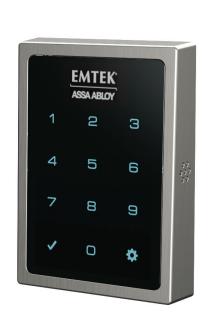
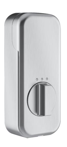
Emtek Powered™ Motorized Touchscreen Keypad SMART Deadbolt – Connected by August Installation & Programming Guide
Open the original PDF document
View PDF


EMPoweredTM Motorized Touchscreen - Connected by August - Keypad Smart Lock Deadbolt

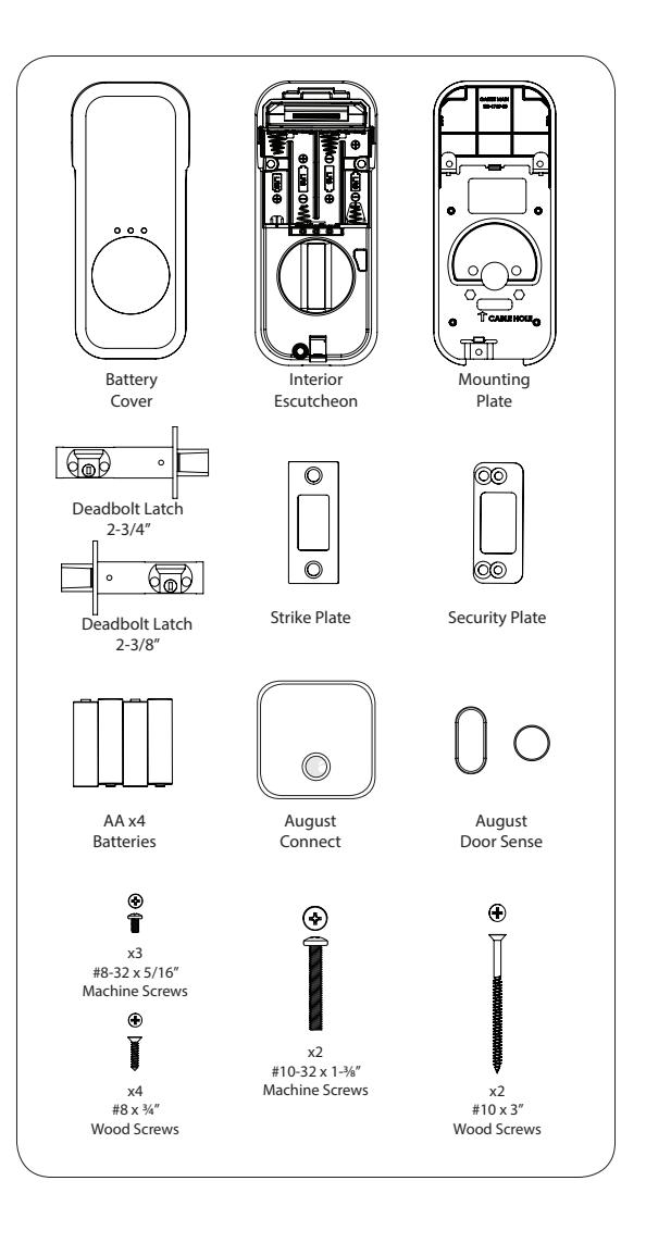
What's in the box
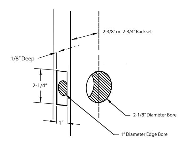
Door Prep
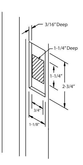
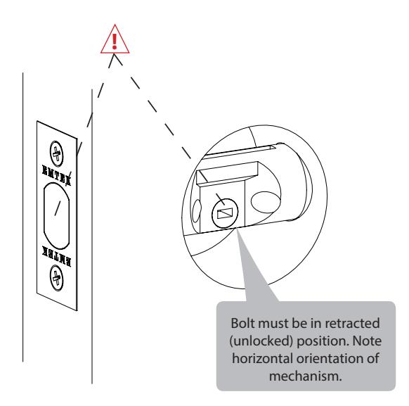
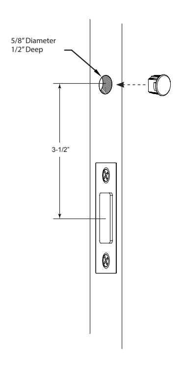
Door Jamb Prep
1
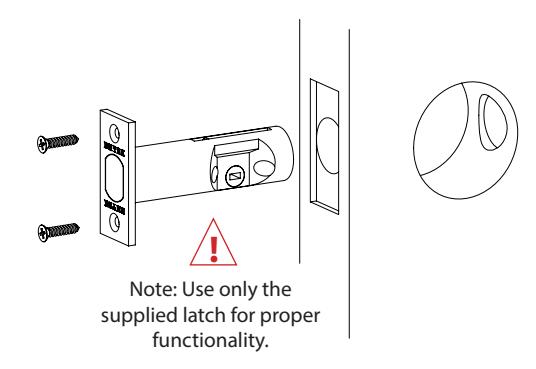
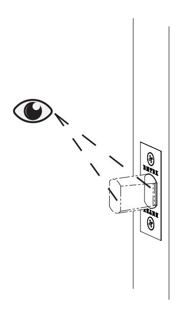
Install Latch & Strike Plate
2
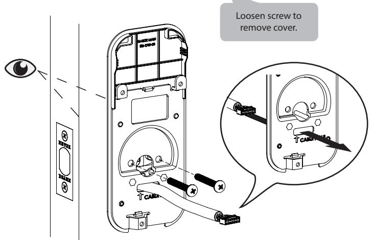
Install Touchscreen Escutcheon
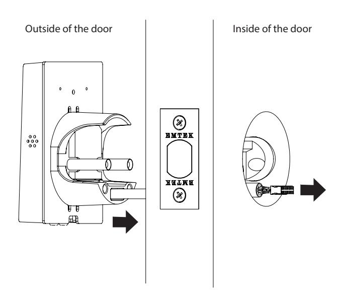
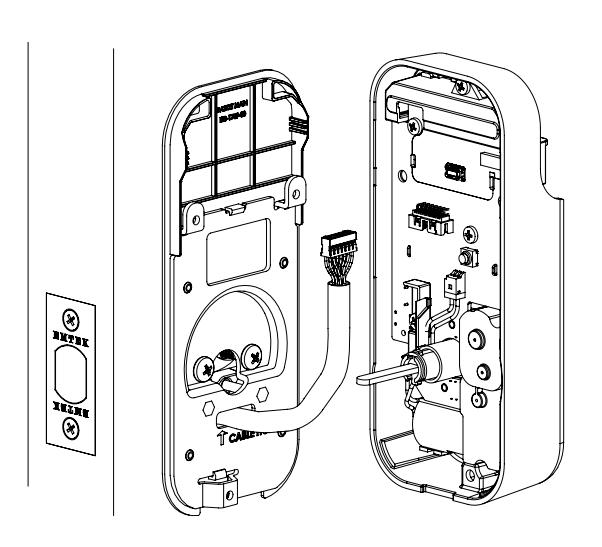
Install Interior Mounting Plate

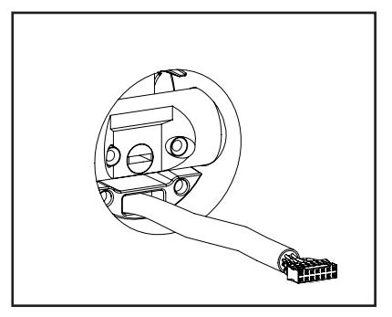
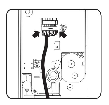
Connect the Cable Assembly
5
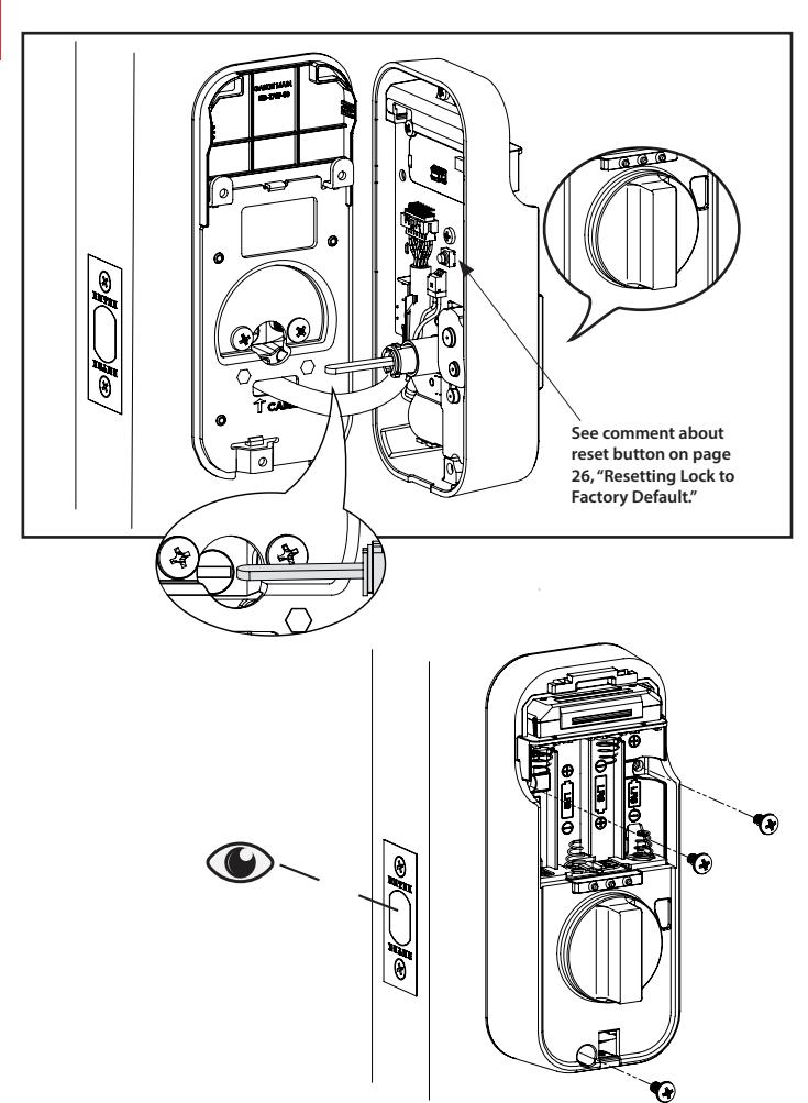
Install Interior Escutcheon
Testing Operation
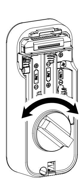
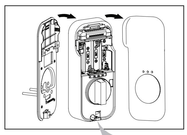
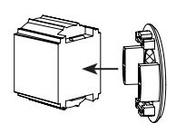
Install Batteries 7
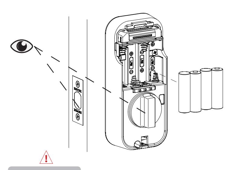
Bolt must be in retracted (unlocked) position before installing batteries.
8
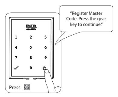
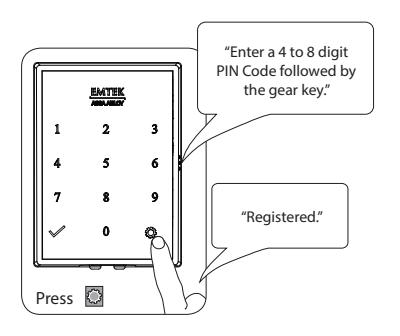
Creating Master PIN Code
Creating a Master PIN Code must be performed upon installation or after resetting the lock to factory default. Programming and use of lock is not possible until this step has been successfully completed.
9
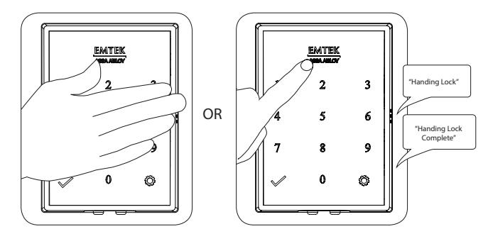
Handing the Lock
Activate the Lock

Go to the August App to Complete 10 Installation
Set Up a Device - EMTEK SMART LOCK
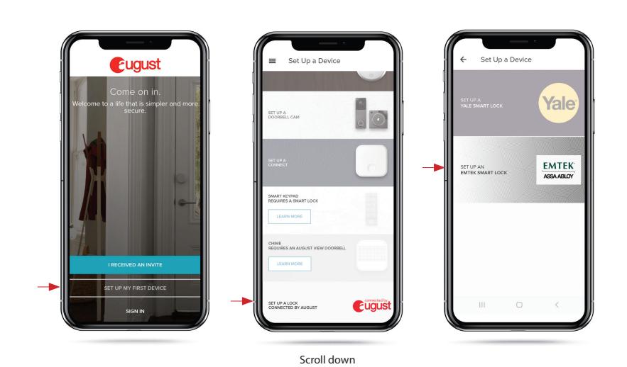
SET UP MY FIRST DEVICE SET UP A LOCK CONNECTED BY AUGUST
SET UP AN EMTEK SMART LOCK

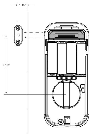
Installing DoorSenseTM with Connected by August Locks - Surface Mount
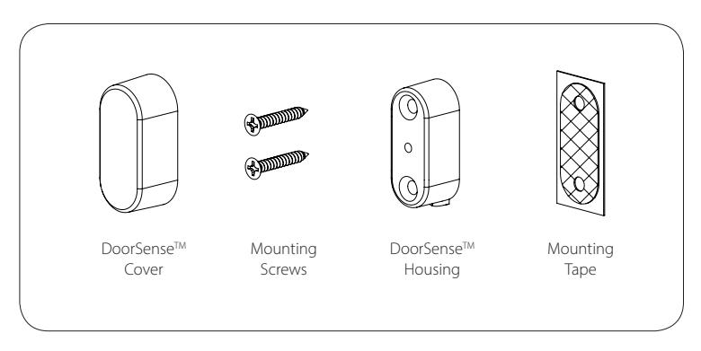
1. Determine mounting location 1-1/2"

Installing DoorSenseTM with Connected by August Locks - Surface Mount
2. Attach mounting tape then screw into frame
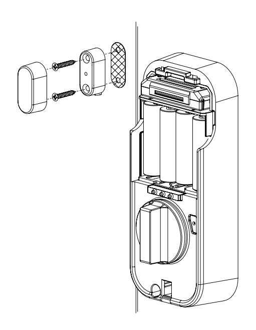
4. Go to the August app to calibrate your Lock

Installing DoorSenseTM with Connected by August Locks - Flush Mount
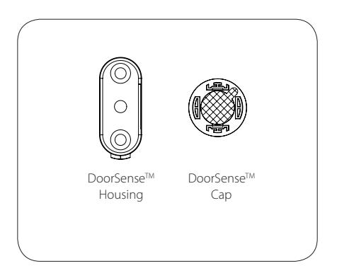
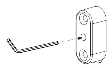
1. Remove magnet from housing and place DoorSenseTM Cap onto the magnet

Installing DoorSenseTM with Connected by August Locks - Flush Mount
2. Drill hole and Insert DoorSenseTM
3. Go to the August app to calibrate your Lock

Go to the August App to Complete Installation
Set Up a Connect Hub
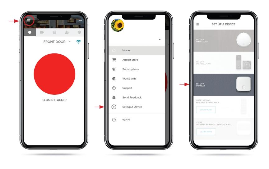
GO TO MENU SET UP A DEVICE SET UP A CONNECT
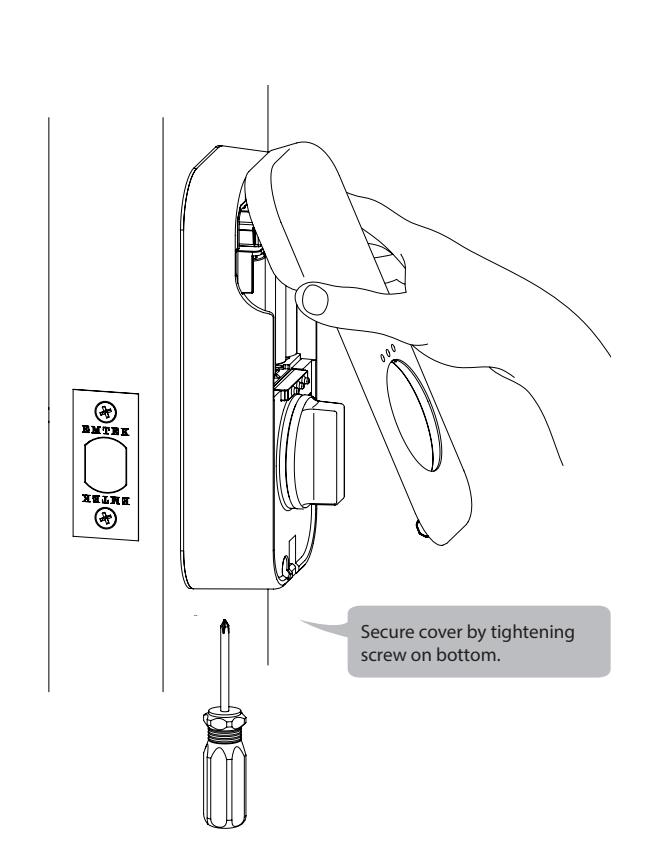
Install Cover
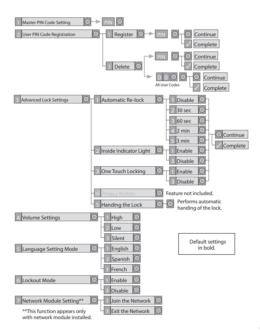
Feature Programming Through Menu Mode Using Master PIN Code*
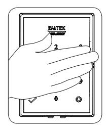
- 1. Touch screen with back of hand or palm to activate.
- 2. Enter 4-8 digit master PIN Code* followed by key. Lock Response: "Menu mode, enter number, press key to continue."
- 3. Enter digit corresponding to the function to be performed followed by the key. Follow the voice commands.
* The Master PIN Code must be registered prior to any other programming of the lock.
Definitions
All Code Lockout Mode: This feature is enabled by the Master PIN Code. When enabled, it restricts all user (except Master) PIN Code access. When attempting to enter a code while the unit is in Lockout, the RED locked padlock will appear on the screen.
Automatic Re-lock Time: After a successful code entry and the unit unlocks, it will automatically re-lock after thirty (30) seconds.
Inside Indicator Light: Located on the interior escutcheon. Shows active status (Locked) of lock and can be enabled or disabled in the Advanced Lock Settings (Main Menu selection #3).
Language Setting Mode: Choosing English (1), Spanish (2) or French (3) becomes the (default) setting for the lock's voice prompts.
Low Battery: When battery power is low, the Low Battery Warning indicator flashes RED. If battery power is completely lost, use the 9 Volt battery override. To use the 9V battery override apply 9V battery, in either direction, to terminals below the touchscreen for backup power option. Wake up the lock and enter your PIN Code to unlock the door.
Master PIN Code: The Master PIN Code is used for programing and for feature settings. It must be created prior to programming the lock. The Master PIN Code will also operate (unlock/lock) the lock.
Network Module Settings: With the optional Network Module installed, this setting becomes available through the Main menu (7) and allows the lock to connect with a network controller.
One Touch Locking: When the latch is retracted, activating the keypad will extend the latch (during Automatic Re-lock duration or when Automatic Re-lock is disabled). When One-Touch Re-lock is not in use (disabled), any valid PIN Code will re-lock the lock.
Previous: While in Menu Mode, pressing this icon cancels the current operation and returns the user to the previous step.
Privacy Mode: Privacy mode is disabled by default Privacy mode is enabled/ disabled in the app.
Shutdown Time: The unit is shutdown (flashing RED) for sixty (60) seconds and does not allow operation after the wrong code entry limit (5 attempts) has been met.
Tamper Alert: Audible alarm sounds if attempting to forcibly remove outside lock from door.
User PIN Code: The User Code operates the lock. Maximum number of User Codes is 250 with Network Module; without Network Module maximum is 25 User Codes. Note: When deleting User Code(s), screen will display User Number (not code) being deleted.
Volume Setting Mode: The volume setting for PIN Code verification is set to Low (2) by default; otherwise it can be set to High (1) or Silent (3) for quiet areas.
Wrong Code Entry Limit: After five (5) unsuccessful attempts at entering a valid PIN Code, the unit will shut down and not allow operation.
Programming Troubleshooting
| Symptom | Suggested Action |
|---|---|
|
Lock does not respond
- door is open and accessible. |
• Touchscreen becomes active when pressed with whole hand. Use larger area of the hand or fingers
and verify contact with at least 3 numbers. • If touchscreen numbers are visible, check to see if they respond when pressed. • Check batteries are installed and oriented correctly (polarity) in the battery case. • Check batteries are in good condition; replace batteries* if discharged. • Check to see if touchscreen harness is fully connected and not pinched. |
|
Lock does not respond
- door is locked and inaccessible. |
• Batteries may be completely discharged.
• Apply 9V Battery to terminals below the touchscreen for backup power option. |
|
Unit is on for a while
then shows no reaction. Lights dim. |
• Batteries do not have enough power. Replace Batteries*. |
|
Unit Chimes to indicate
code acceptance, but the door will not open. |
• Check door gaps for any foreign objects between door and frame.
• Check that the wire harness is firmly connected to the PCB. |
|
Unit operates to allow
access, but will not auto matically re-lock |
• Check to see if Auto Re-lock Mode is enabled.
• Disable Auto Re-lock Mode to lock the door (automatically). • If low battery indicator is lit (see below), change batteries*. |
|
PIN Codes will not
register. |
• PIN Codes must consist of 4 to 8 digits to register.
• The same PIN Code cannot be used for multiple users. • Registration/management of PIN Codes is set by the authority of the Master Code, which is set first. • Contact the Master user. • User Codes must be entered within 5 seconds (while touchscreen is active) or process will have to be restarted. • Check or gear cannot be used as part of the PIN Code. |
|
Upon entering a PIN
Code and pressing key, the unit displays "invalid code" error or lock times out without responding. |
• Lockout Mode is enabled.
• Only the Master user can enable/disable Lockout Mode. • Contact the Master user. |
|
Upon entering a PIN
Code and pressing the key, the red padlock icon appears and there are different tones. |
• Check to see if the lock is set to Lockout Mode.
• Setting/managing Lockout Mode is done through Master Code only. • Contact the Master user. |
|
The unit operates but it
makes no sound. |
• Check to see if Silent Mode is enabled (see Feature #4) |
|
The unit responds "Low
Battery" |
• This is the alert to replace the batteries. Replace all four (4) batteries*
with new AA Alkaline batteries. |
|
Upon entering a PIN
Code and pressing the key, the unit responds "Wrong number of digits". |
• The digits entered were incorrect or incomplete. Re-enter the correct code
followed by the check key. |
* When batteries are replaced. Network Module locks have a real time clock that will be set through the User Interface (UI); it is recommended to verify correct date and time particularly those locks operating under Daylight Saving Time (DST).
Hardware Troubleshooting
Cycle lock in both the locked and unlocked positions. If problems are found:
Door is binding
- a. Check that door and frame are properly aligned and door is free swinging.
- b. Check hinges: They should not be loose or have excessive wear on knuckles.
Bolt will not deadlock
- a. Check for sufficient clearance of the bolt within the strike-side jamb. Correct this by increasing the depth of the pocket for the bolt.
- b. Check for misalignment of bolt and/or strike which may be preventing bolt from properly entering the strike. With the door open, extend and retract the bolt; if it is smooth, check the strike alignment.
Bolt does not extend or retract smoothly
- a. Bolt and strike are misaligned, see above.
- b. Check the backset of door relative to adjustments already made to bolt.
- c. Verify proper door preparation and re-bore holes that are too small or misaligned.
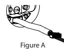
- d. Verify keypad wire harness is routed under the bolt (see Fig. A)
- e. Verify bolt is installed with correct side up (Fig. A)
Keypad numerics are scrolling
Remove interior escutcheon and check to ensure that the wire harness lies flat against the back recessed area and is properly routed along the side of the escutcheon and tucked under the plastic cable guide.
NOTE TO INSTALLER AND CONSUMER
While EMTEK has included several features to prevent lockout (9V battery jumper, low battery warnings), it is still possible for a lockout situation to occur. Because this product does not have a mechanical override (a key), EMTEK recommends to use this product in an environment where there are additional entry points into the dwelling.
Resetting Lock to Factory Default
When lock is reset to factory defaults, all User Codes (including the Master PIN Code*) are deleted and all programming features are reset to original default settings (see below).
- 1. Remove battery cover and batteries.
- 2. Remove the interior escutcheon to access the reset button.
- 3. The reset button (see page 8, Step 5) is located beside the PCB cable connector.
- 4. While pressing the reset button (Minimum of 3 seconds) reinstall batteries. Release reset button.
- 5. Replace battery cover.
Upon reset, Master PIN Code creation is the only option available and must be performed prior to any other programming of the lock.
Factory Settings
| Settings | Factory Settings |
|---|---|
| Master PIN Code | Registration required* |
| Automatic Re-lock | Disabled |
| Inside Indicator Light | Disabled (Off) |
| One Touch Locking | Enabled |
| Volume Setting | Enable (Low) |
| Language Setting | English |
| Lockout Mode | Disabled |
| Automatic Re-lock Time | 30 Seconds |
| Wrong Code Entry Limit | 5 Times |
| Shutdown Time | 60 Seconds |
* The Master PIN Code must be registered prior to any other programming of the lock.
Compliance
FCC INTERFERENCE STATEMENT
This device complies with Part 15 of the FCC Rules. Operation is subject to the following two conditions. (1) This device may not cause harmful interference, and (2) this device must accept any interference received, including interference that may cause undesired operation.
This equipment has been tested and found to comply with the limits for a Class B digital device, pursuant to Part 15 of the FCC Rules. These limits are designed to provide reasonable protection against harmful Interference in a residential installation.
This equipment generates, uses and can radiate radio frequency energy and, if not installed and used in accordance with the instructions, may cause harmful interference to radio communications.
However, there is no guarantee that interference will not occur in a particular installation If this equipment does cause harmful interference to radio or television reception, which can be determined by turning the equipment off and on, the user is encouraged to try to correct the interference by one of the following
- Reorient or relocate the receiving antenna.
- Increase the separation between the equipment and receiver
- Connect the equipment into an outlet on a circuit different from that to which the receiver is connected.
- Consult the dealer or an experienced radio/TV technician for help.
FCC Caution: Any changes or modifications not expressly approved by the party responsible for compliance could void the user's authority to operate this equipment.
This transmitter must not be co-located or operating in conjunction with any other antenna or transmitter.
Radiation Exposure Statement:
This equipment complies with FCC radiation exposure limits set forth for an uncontrolled environment. This equipment should be installed and operated with minimum distance 20cm between the radiator & your body.
INDUSTRY CANADA COMPLIANT
This device complies with RSS·210 of the Industry Canada Rules Operation Is subject to the following two conditions: (1) This device may not cause harmful interference, and (2) this device must accept any interference received, including interference that may cause undesired operation.
Radiation Exposure Statement:
This equipment compiles with IC radiation exposure limits set forth for an uncontrolled environment. This equipment should be installed and operated with minimum distance 20cm between the radiator & your body.
INDUSTRIE CANADA CONFORME
Ce dispositif est conforme à la norme CNR-210 d'industrie Canada applicable aux appareils radio exempts de licence. Son fonctionnement est sujet aux deux conditions suivantes: (1) le dispositif ne doit pas produire de brouillage préjudiciable, et (2) ce dispositif doit accepter tout brouillage reçu. y compris un brouillage susceptible de provoquer un fonctionnement indésirable.
Déclaration d'exposition aux radiations:
Cet équipement est conforme aux limites d'exposition aux rayonnements IC établies pour un environnement non contrôle. Cet équipement doit être installé et utilisé avec un minimum de 20 cm de distance entre la source de rayonnement et votre corps.

IN8-EMPWRUNTY REV 19B 11-26-19
Copyright © 2019, EMTEK Products, Inc. an ASSA ABLOY Group company. All rights reserved. Reproduction in whole or in part without the express written permission of EMTEK Products, Inc. is prohibited.
WARNING: This product can expose you to chemicals including lead, which is known to the state of California to cause cancer and birth defects or other reproductive harm. For more information go to www.P65Warnings.ca.gov.