Edwards Signaling XAL-53 Installation Instructions
Open the original PDF document
View PDF

INSTALLATION, OPERATION & MAINTENANCE DATA SHEET
"XAL" SERIES FIRE ALARM STATIONS
FOR CLASS I, GRP. C & D, CLASS II, GRP. E, F & G AND CLASS III HAZARDOUS LOCATIONS. DIRECTIONS FOR INSTALLATION
CAUTION: Before beginning installation, make sure that the supplying circuit is turned OFF.
NOTE: Connect <u>only</u> copper wire to this device. Be sure to check the catalog number on the box or cover with the number on the carton(s) to be certain you have the correct components.
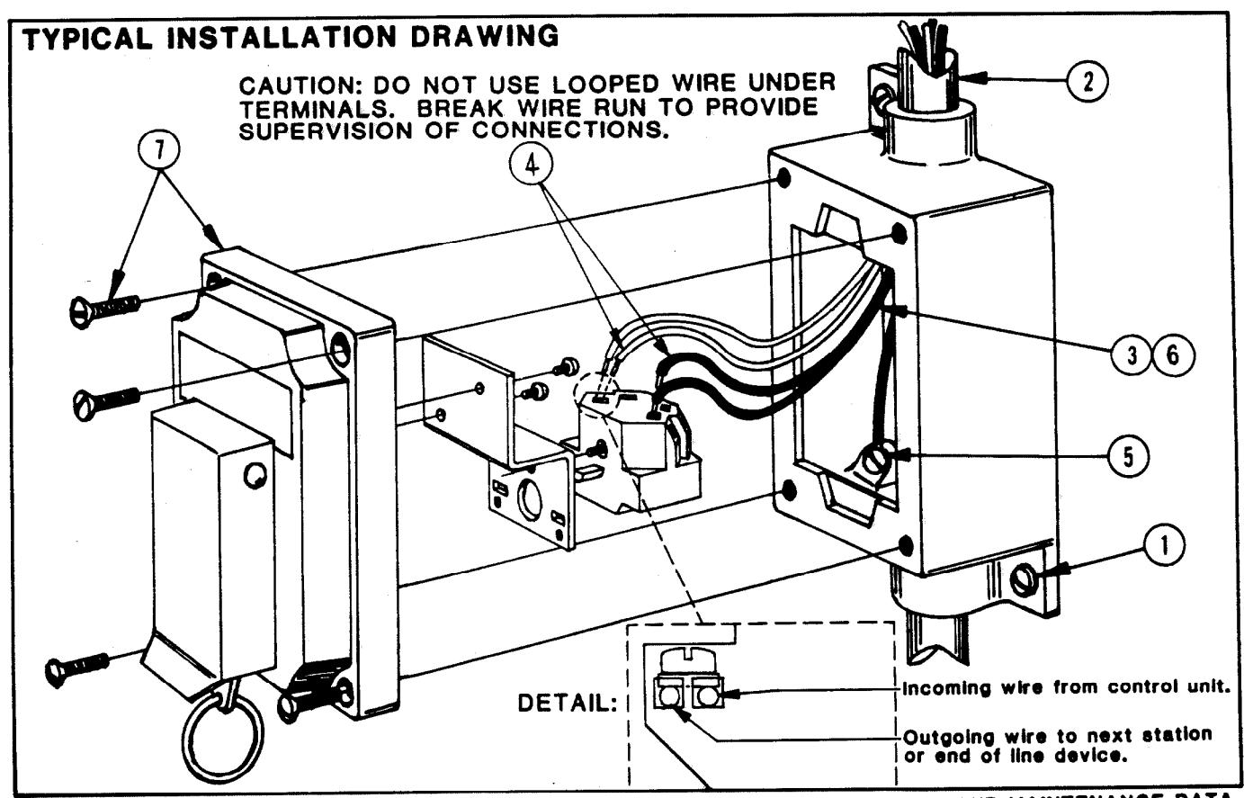
- ① Using the Installation Drawing below as a guide, install the SWB Splice Box, using the cast-on mounting lugs. (1/4"dia. bolts are recommended for secure mounting.)
- (2) Attach the conduit to the box.
- 3 Pull the wires through the conduit and into the splice box.
- Make all wiring connections as system requires. Strip off approximately 11/32" of the wire insulation, exposing the bare conductor. Insert conductor into one side only of the N.O. or N.C. contact (See
detail). Tighten captive screw securely onto wire. Do the same with all other wires in the system.
- ⑤ Connect the ground wire to the ground screw in the splice box.
- 6 Push the connected wires into the splice box.
- To complete the installation, install the cover assembly. The four cover bolts should be tightened so that a .0015" feeler gauge will not enter more than 1/8" at any point around the flange joint.
- 8 When the entire system has been wired and secured, turn ON the supplying circuit to test the device.
NOTE: All installations must comply with applicable local and /or National Electrical Code.
P/N 00911955 FORM NO. K0993 R3/95
SEE REVERSE SIDE FOR OPERATIONAL AND MAINTENANCE DATA.
OPERATIONAL DATA
This enclosure is made of cast, copper-free aluminum alloy. It is suitable for Class I, Groups C & D, Class II, Groups E, F & G and Class III hazardous locations. Like all electromechanical devices, these control stations require occasional maintenance. Parts may wear out or become defective due to adverse environmental conditions.
MAINTENANCE DATA
CAUTION: Disconnect this device from the supplying circuit before removing the cover.
To prevent corrosion, lubricant should be occasionally applied, as follows: Killark "LUBG" lubricant to box/cover flanges; and Dow Corning Molykote 33 Grease, light consistency, to operator shaft. Keep all flanges clean and free of scratches. Some internal service parts are available. Consult the Killark factory for parts breakdowns.
GENERAL INFORMATION
|
CATALOG
NUMBER |
CONDUIT
SIZE |
CONTACT ARRANGEMENT | |
|---|---|---|---|
| NOT ACTIVATED POSITION | ACTIVATED POSITION | ||
| XAL-53 | 3/4" | 3 4 |
1 • 2
3 • 4 |
All units are rated 120 VAC, 60 HZ. Contact Block Rating: 10 Amps continuous, NEMA A600, NEMA P600. Wire Range: (2) #12 thru #24 Solid or Stranded.
REMEMBER TO SAVE ONE OF THESE SHEETS FOR MAINTENANCE PERSONNEL.
| MAINTENANCE MANAGER: Please record the following information for your records. | ||
|---|---|---|
| COMPLETE CATALOG NO(As shown on package) | ||
| DATE OF INSTALLATION: | ||
| INSTALLED BY: | ||