Edwards Signaling V9006 Hazardous Location Smoke Detetctor Installation Instruction
Open the original PDF document
View PDF

INSTRUCTIONS
Smoke Detector for Classified Areas U5005
APPLICATION
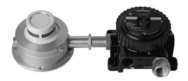
The Det-Tronics U5005 Smoke Detector is a sensitive yet rugged, state-of-the-art protection device that is designed for classified areas in hazardous industrial and commercial locations. The detector is designed to operate effectively with both slow smoldering and fast burning fires. Typical applications that use the U5005 include:
- • Combustible storage facilities
- • Munitions manufacturing
- • Volatile chemical storage
- • Chemical processing plants
- • Petroleum refineries
- • Turbine enclosures.
DESCRIPTION
The photoelectric smoke detector uses a solid state infrared emitting diode (IRED) and a light sensing photovoltaic cell arranged in a labyrinth assembly. The labyrinth permits free access to smoke but restricts external light. Because of its critical function to the operation of the detector, each IRED is selected with extreme care and is subjected to rigorous pre-production testing to ensure long-term reliability and performance.
During normal operation (no smoke), the detector samples the air approximately every four seconds for a period of less than one millisecond. The photo-voltaic smoke cell, which is placed at an angle to the pulsed invisible light source, is sensitive to the infrared light in the specified frequency emitted by the IRED light source and is designed to receive a signal only when the pulsed IRED source is activated. See Figure 1.
When smoke enters the chamber, the light from the IRED reflects off the smoke particles and reaches the photovoltaic smoke cell. When the amount of light reflected by smoke reaches the factory set threshold level, the smoke alarm circuit is actuated.
The detector will respond to a slow smoldering fire when smoke in the chamber reaches the pre-set sensitivity setting, typically 2.3% .
If a fast burning fire should occur, including fires in flammable liquids and other materials such as plastics that generate black smoke, the abnormally rapid movement of smoke into the detection chamber is sensed by a special rate compensating circuit. An increase in smoke within the detection chamber that exceeds a pre-set rate causes the rate compensation circuit to increase the intensity of the light source, which increases detector sensitivity. If the smoke continues to build at this rate, an amplifier circuit is triggered and the unit generates an alarm. If not, the detector reverts to normal sensitivity.
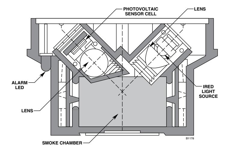
Figure 1—Cross Section of Sensing Chamber Assembly
In normally smoky atmospheres the detector will not go into alarm as long as the concentration is less than the fixed sensitivity of the detector. This results in a sensitive and positive response with the lowest potential for unwanted alarms.
The main enclosure of the detector contains the electronic circuitry, alarm relay, and supervision relay.
Failsafe Operation
To ensure reliable operation, the U5005 is equipped with self-checking circuitry. A regulation photodiode, which is matched to the smoke detection circuit, continuously monitors the output intensity of the IRED and adjusts it as necessary to compensate for an accumulation of dust or other contaminants, or any other variation that can occur with temperature and time. A power supervision relay in the detector provides a trouble output signal in the event of an input power failure.
The detector uses extensive filtering against RF and transient interference. In addition, there is a 2 second time delay before an alarm is generated.
The printed circuit board inside the detector is coated to minimize the possibility of problems caused by moisture accumulation.
Detector Outputs
The detector provides a set of Form A (SPST) NO contacts for connection to the alarm output circuitry and a set of SPST NC contacts for supervision of input power. An auxiliary set of Form C (SPDT) NO/NC alarm relay contacts is also provided for controlling remote annunciation devices.
The alarm output latches on in the event of an alarm and an LED located on the outer surface of the housing is illuminated to provide a visual indication that an alarm condition has occurred. The detector is reset by momentarily interrupting input power.
SPECIFICATIONS
OPERATING VOLTAGE—
20 to 28 Vdc filtered supply, with less than 1.4 vpp at 60 to 120 Hz.
OPERATING CURRENT—
Standby: 10 milliamperes. Alarm: 35 milliamperes.
TEMPERATURE RANGE—
Operating: –13°F to +140°F (–25°C to +60°C). Storage: –67°F to +185°F (–55°C to +85°C).
alarm and supervisory RELAY CONTACT RATING—
1.0 ampere at 30 Vdc, SPST.
AUXILIARY ALARM RELAY CONTACT RATING—
2.0 amperes at 30 Vdc, Form C, SPDT.
junction box—
Body material: Copper-free aluminum. Conduit Fitting: 25 mm (female).
CERTIFICATIONS—
CSA: Certified for use in Class I, Division 2, Groups A, B, C and D hazardous

DIMENSIONS—
See Figure 2.
weight—
2 pounds (0.91 kilogram)
INSTALLATION
The U5005 is intended for surface mounting. See Figure 2. The mounting screw holes are counterbored for No. 8 flat-head screws. Electrical equipment that is used in conjunction with the smoke detector is connected to the detector using a terminal strip located in the junction box that is furnished with the unit.
Detector Location
The smoke detector is normally mounted on the ceiling not less than six inches from a side wall. The exact location of the detector must be determined by an evaluation based on engineering judgment supplemented, if possible, by field tests.
For additional information on detector location and spacing, contact the National Fire Protection Association, Batterymarch Park, Quincy, Mass. 02269, and request a copy of NFPA Number 72, the Standard on Automatic Fire Detectors.
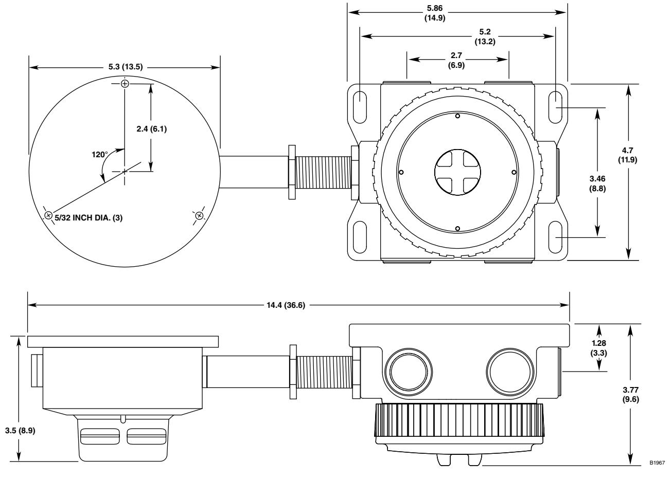
Figure 2—U5005 Dimensions in Inches (Centimeters)
Mounting the Detector
- 1. Using three No. 8 flat head screws placed through the counterbored holes in the detector flange, secure the detector to the surface location. Secure the junction box if necessary.
- 2. Remove the cover from the junction box and complete installation of system conduit. Feed the external wiring through the remaining junction box entry or M25 to 3/4 inch adapter. Use care not to damage the wires by twisting them when installing the junction box.
- 3. Connect the external wiring to the appropriate terminals and re-install the junction box cover. See Figures 3, 4 and 5 for wiring details.
Detector Connections
The U5005 contains two sets of relay contacts:
- 1. One set of NO Alarm contacts close upon detection of smoke.
- 2. One set of NC Trouble contacts close when the detector is powered.
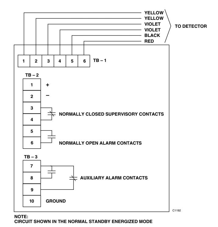
Figure 3—Wiring Terminals
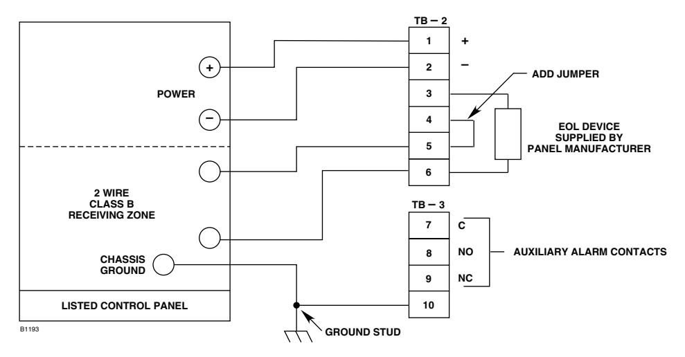
Figure 4—Single Detector Wiring
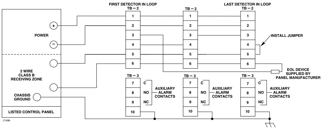
Figure 5—Multiple Detector Wiring
MAINTENANCE
Regularly scheduled maintenance is normally not needed, however, periodic cleaning of the smoke chamber may be necessary when detectors are located in abnormally dirty or dusty environments. Vacuuming around the smoke chamber housing prior to blowing out the chamber with a "dry air" hose is recommended.
NOTE
The U5005 is not designed to be serviced or repaired in the field. Disassembly of the detector in the field will void the warranty. If service or repairs are required, return the entire unit to the factory.
The smoke detector can be tested using the same methods employed for any photo-electric detector. We recommend using canned smoke for periodic maintenance of the detector.
DEVICE REPAIR AND RETURN
Prior to returning devices or components, contact Detector Electronics so that a Service Order number can be assigned. A written statement describing the malfunction must accompany the returned device or component to expedite finding the cause of the failure. Return all equipment transportation prepaid to the factory in Minneapolis.
Specifications subject to change without notice.
Det-Tronics and the DET-TRONICS logo are registered trademarks or trademarks of Detector Electronics Corporation in the United States, other countries, or both. Other company, product, or service names may be trademarks or service marks of others.


Detector Electronics Corporation
6901 West 110th Street • Minneapolis, Minnesota 55438 USA Operator: (952) 941-5665 or (800) 765-FIRE Customer Service: (952) 946-6491 • Fax (952) 829-8750 http://www.det-tronics.com • E-mail: det-tronics@det-tronics.com