Edwards Signaling Series 300-BT Safety Switches Installation Instructions
Open the original PDF document
View PDFSeries 300-BT Safety Switches
Installation Instructions
Mounting Configurations
The interlock switch and actuator should be mounted in only three configurations for actuation:
Figure 1
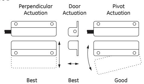
Figure 2
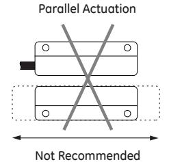
The parallel actuation can result in on/off/on (double actuation) signal if the actuator passes by the switch rather than coming to rest in proximity to it. This is NOT a recommended configuration for safety interlock applications.
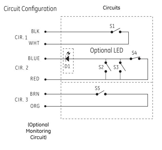
*Circuits shown with magnet actuator away from switch.
- S1 Normally open reed switch, closed when actuator is within specified sense range
- S2, S3 Normally open reed switches, will close if misaligned or tampered with a standard magnet
- S4 Biased closed reed switch, open when actuatior is between specified sense range
- S5 Normally open reed switch, closed when actuator is within specified sense range
N.O. circuit: Black and white wires.
- N.C. biased tamper circuit: Red and blue wires.
- N.O. monitor circuit: Orange and brown wires.
Installation
- 1. Position the switch and actuator so the labels are reading in the same direction.
- 2. Mount the switch on the stationary frame of the machine and mount the actuator on the moveable guard, door or gate. Keep the switch and actuator within the listed sense range.
- See Figure 1 and Figure 2 for recommended mounting configurations.
- 3. Mounting on a ferrous material will effect the sense range a minimum of 50%. However, a 1/4" non-ferrous spacer positioned under the actuator and/or switch should restore most of the lost sense range.
- 4. For best protection against operator defeat, mount with non removable screws, bolts or nuts (see Accessories).
- 5. CAUTION: When not used with a INT safety relay particular care must be taken to determine the actual load of the switch circuit. High voltage transients from coils, motors, contactors, and solenoids must be considered. Transient protection, such as back-to-back zener diodes (TransZorb®) or an RC network, is recommended for such loads to ensure that maximum ratings of the switch are not exceeded. Not recommended to be used with tungsten filament loads because of high current inrush surges. Line capacitance and load capacitance must be considered. Excessive line capaci tance can be caused by cable lengths over 50' when using a maximum 48 VAC. A resistor can be added in series to limit the inrush current (at least 48 Ohms for 24V applications). The resistor can be added in series just before the load. The voltage drop and the power rating of the resistor must be considered.
Voltage drop =I•R; Watts = I2 R (I = maximum continuous current of the load).
6. When mounting the switch on an ungrounded machine, ground the switch housing by connecting your ground lead to one of the switch mounting screws.

Series 300-BT Safety Switches
Installation Instructions
Wiring Diagram For Category 3
Inputs shown with safety gates/guards in closed position.
When guards are closed, safe outputs are closed.
One 300-BT Series GuardSwitch required for each safety gate, one INT relay for each machine.
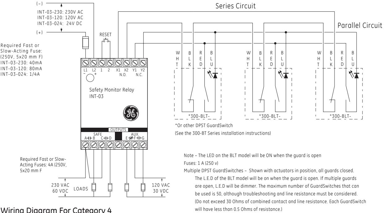
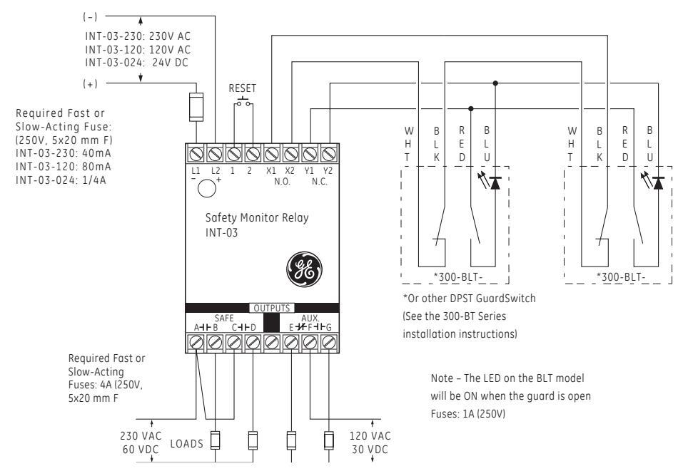
Wiring Diagram For Category 4
Inputs shown with safety gates/guards in closed position.
When guards are closed, safe outputs are closed.
Two 300-BT Series GuardSwitches with one INT relay are required for each safety gate.
When first applying the GuardSwitch Monitor Relay, the inputs must be cycled to check for proper operation before the output contact close. To cycle the inputs, the guard must be opened and then closed. This start-up test is sufficient; however, we recommend that the proper operation of the switches and relay be checked at least every 24 hours.


Series 300-BT Safety Switches
Installation Instructions
CE Compliance Information
These switches are TÜV certified for CE applications only when used with the INT Series Safety Monitor Relays. See Risk Category 3 and Category 4 wiring diagrams.
GE Interlogix Industrial
For a full-sized signed version, see page 26.


available upon request.
European Directives
Machinery Directive (89/392/EEC) EMC Directive (89/336/EEC) Low Voltage Directive (73/23/EEC)
Specific European Standards
EN60204-1 Safety of electrical equipment
of industrial machines.
EN292 Part 1, 2 Safety of Machinery, basic
terminology, technical principles.
EN954-1 Risk Assessment Category 3 or
4 depending on wiring method,
see diagrams.
EN55081-2 Electromagnetic Emissions. EN550082-2 Electromagnetic Immunity.
EN1088 Interlocking Devices. EN 947-5-3 Control Circuit Devices.
EN 50178 Safety of Electrical Equipment.
IEC 664-1 Insulation requirements. IEC 68 part 2-1, 2-2, 2-3, 2-8, 2-14,
2-27, 2-30.
Notes:
- 1. Humidity Rating: 30 to 95%
- 2. Environment: Pollution Degree II.
- 3. Correct use of this control devise is an essential part of proper machine cycle control.
- 4. Failure to follow ALL instructions could lead to serious bodily injury or death.
- 5. Maintenance to be done by qualified personnel only.
- 6. The connecting cables between the INT de vices and the switches must be located in an IP 23 type enclosure (minimum).
- 7. The mounting for the switch and the acuator must be accomplished per this specification.
- 8. Non-removable hardware must be used for installation.
- 9. The housing of the 300-BT Series Guard Switches must be connected to the PE (Primary Earth) ground circuit via a lock washer on the mounting screw. The PE ground symbol must be placed adjacent to the screw.
