Edwards Signaling Series 100 Interlock Switches Installation Instructions
Open the original PDF document
View PDF

Series 100 Interlock Switches
Installation Instructions
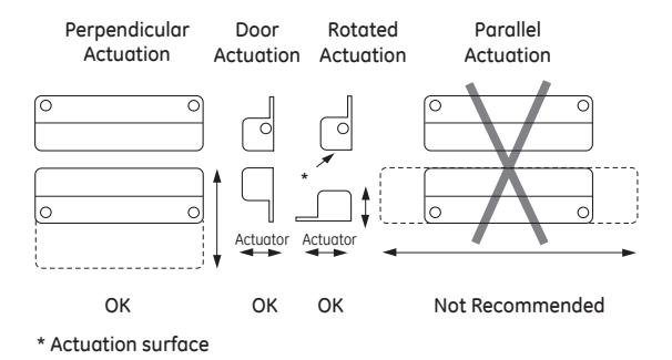
Surface Mounting Configurations
Figure 1
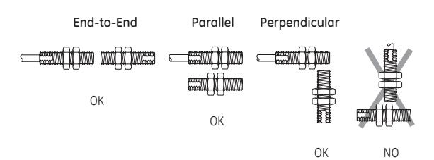
Barrel Switch Mounting Configurations
Figure 2
Installation
Mounting Instructions
- 1. Select a mounting location where the switch and actuator can be installed with their labels reading in the same direction.
- 2. Mount the switch on the stationary frame of the machine and the actuator the moveable guard, door, or gate. Switches Models 125, 126, 128C & 129: Slightly over-drill holes for easy insertion. The switch and actuator should easily slide or screw into the predrilled holes – DO NOT force or hammer. This may damage switch.
- 3. For best protection against operator defeat, mount with non removable screws, bolts, or nuts. (See accessories)
- 4. The switch and actuator must be mounted so that the actuator moves in one of the approved directions ( Figure 1 and Figure 2).
- 5. Parallel actuation is NOT recommended except for barrel type switches. An on/off/on double actuation signal may result when the magnet passes by the switch.
- 6. When mounting on a hinged gate or door, mount the switch and actuator at least 6" away from the hinges so a more face to face approach is achieved.
- 7. The actuator can be mounted at a 90° rotation.
- 8. Keep the switch and actuator within the listed sense range (see specific switch electrical specifications).
- 9. Mounting on a ferrous (steel) material will reduce the sense range a minimum of 50%. A 1/4" nonferrous (plastic or aluminum) spacer installed under the actuator and switch will restore most of the lost gap.
- 10. When mounting a metal switch to an ungrounded machine, connect the ground lead to one of the switch mounting screws.
CAUTION — Particular care must be taken to determine the actual load of the switch circuit.
- 1. Surges from coils, motors, contactors, solenoids and tungsten filaments must be considered.
- 2. Transient protection, such as back-to-back zener diodes (Transorb) or an RC network, is recommended for such loads to ensure that maximum ratings of the switch are not exceeded.
- 3. Line capacitance and load capacitance must be considered. An in-line resistor can be added to limit the inrush current.
- 4. The resistor can only be added in series with the last wire just before the load.
- 5. The voltage drop and the power rating of the resistor must be considered.
Voltage drop = I • R Watts = I2 • R
( I = maximum continuous current of the load)