Edwards Signaling Integrity Series INT-03 Monitor Relay Installation Sheet
Open the original PDF document
View PDF

Integrity Series INT-03 Monitor Relay Installation Sheet
Description
The INT-03-024 or INT-03-120 Safety Monitor Relay is intended for use as a part of a safety circuit in guard interlock applications. It is a safety relay which uses positive guided relays, configured for selfchecking, to inhibit machine start-up in the event of an internal component failure.
Both normally-open and normally-closed inputs are required. Multiple NO contacts can be wired in series while multiple NC contacts can be wired in parallel. Upon failure of either the NO or NC contact, the relay will turn off and prevent restart. The INT-03 relay can also monitor contacts on external relays for controlling expansion block relays (Sentrol INT-05 and INT-06).
Notes
- Relay conforms to Pollution Degree II, meets EN1760-1:1998, and must be installed in an IP54-type enclosure.
- The wire insulation of connected devices must be rated for 250 VAC. The relay meets basic insulation requirements only.
- Input devices must meet requirements of EN60947-5-1.
- The relay must be connected to a primary disconnect device that meets the requirements of EN60947-3.
- System total response time must not exceed 200 ms.
- Controller meets IP20 and must be connected to safety category 4 mat or sensing device.
- Test system before operation and after machine maintenance. Controller does not require maintenance.
- The complete system should be tested weekly. If a fault occurs, contact Sentrol Industrial.
Installation
Guardswitch inputs: Wire the GuardSwitches in series and in parallel as shown in the wiring diagram. When first applying power to the GuardSwitch Monitor Relay, with no jumper or button from Terminal 1 to Terminal 2, the relay will not energize.
With a jumper installed from Terminal 1 to Terminal 2, the relay energizes when all guards are in place (autostart).
With a RESET button installed from Terminal 1 to Terminal 2, the relay energizes after all guards are in place and the RESET button is pressed. The monitor contacts must also be closed.
Authorized outputs: The designer must perform a risk analysis and be aware of the applicable safety standards of their machine. The designer has a choice of how to use the output contacts.
The output contacts can be used in combination with an Emergency Stop Relay circuit with a "reset" function. ("The restoring of an interlocked safeguard shall not initiate machine motion or operation where this can result in a hazardous condition." IEC 204-1.)
The reset circuit should not be wired to disconnect power to the GuardSwitch Monitor Relay, or it will be difficult to distinguish between a GuardSwitch failure and a normal reset function.
Input power: The GuardSwitch Monitor Relay is available in either a 24 VDC or 120 VAC model. Make sure the correct model is used before applying power as shown in the wiring diagram.
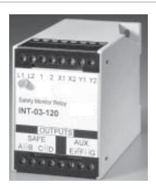
Figure 1: Dimensions

Figure 2: Typical wiring diagram
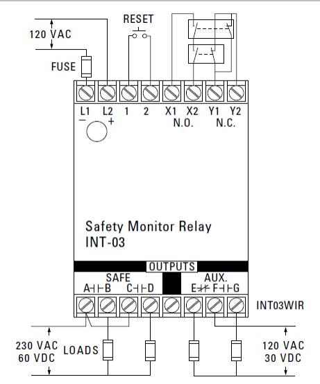
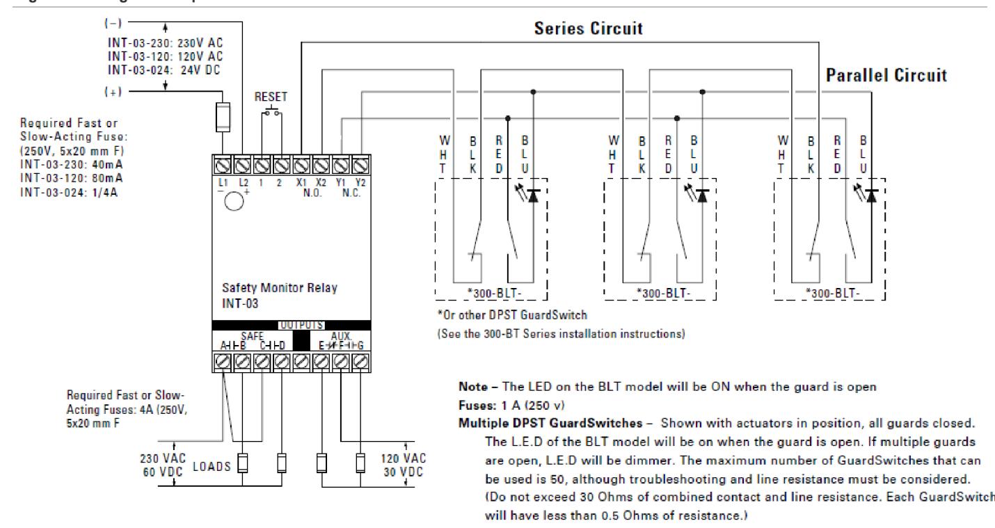
Figure 3: Wiring for multiple switches
Notes
• GuardSwitches are shown with the actuators in position — guard is closed. One 300-BT Series GuardSwitch is required for each safety gate. Up to 50 switches can be used with INT-03. When using the BLT switch models, the voltage drop (30 Ω) must be taken into consideration.
• Only outputs AB and CD are safety outputs. Auxiliary form C output E, F, G may fail in an unsafe condition and should only be used for signaling.
• The circuit wiring in Figure 3 can be as follows: WHT (White) wire can be WHT or YLW (yellow), BLU (Blue) wire can be BLU or GRN (Green)
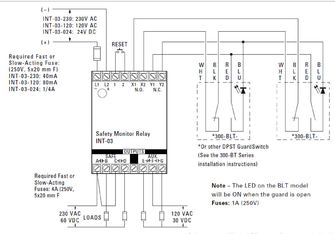
Figure 4: Wiring for category 4
Notes
• GuardSwitches are shown with the actuators in position — guard is closed. Inputs are shown with safety/guard in closed position. Two 300-B Series Guardswitch and one INT relay are required for each safety gate.
- Only outputs AB and CD are safety outputs. Auxiliary form C output E, F, G may fail in an unsafe condition and should only be used for signaling.
- The circuit wiring in Figure 4 can be as follows: WHT (White) wire can be WHT or YLW (yellow), BLU (Blue) wire can be BLU or GRN (Green)
Specifications
AUX contacts
| Power | Guards | E, G | F, G | |
|---|---|---|---|---|
| Off | Open or closed | Closed | Open | |
| On | Closed | Closed | Open | |
| On | Open | Open | Closed |
General specifications
|
Weight:
INT-03-24 INT-03-120/230 |
9 oz.
15 oz. |
| Field wiring size | 12 gauge max. |
| Temperature range | 32°F to 149°F (−0°C to 65°C) |
| Relative humidity | 30 to 95% noncondensing |
| Power supply (+, − or L1, L2) | |
|
INT-03-024
Required fuse |
24 VDC ±15% 100 m
1/4 A (250 V, 5 × 20 mm, F/T) |
|
INT-03-120
Required fuse |
120 VAC +10% −20%, 5 VA, 50/60 Hz
80 mA (250 V, 5 × 20 mm, F/T) |
| Control inputs (X1, X2 & Y1, Y2 terminals) | |
| Open circuit voltage | 24 VDC |
| Closed circuit current | 24 mA |
| Contact resistance | 30 Ω max. |
| Simultaneity | 500 ms typical |
| Safe outputs (A, B / C, D terminals) | |
| Voltage | 230 VAC / 60 VDC |
| Current | 4 A (resistive) each output |
| Response time | < 100 ms |
| Fuse | 4 A, 250 V, 5 × 20 mm |
| AUX. signaling outputs (E, F, G terminals) | |
| Voltage | 120 VAC / 30 VDC |
| Current | 1 A (resistive) |
Note: Transient protection is required across the load when switching an inductive load.
Ordering/electrical specifications
| Part number | Power input (L1, L2) | Input fuse required |
|---|---|---|
| INT-03-024 | 24 VDC ±20% | Fast acting 1/4 A (250 V, 5 x 20 mm, F/T) |
| INT-03-120 | 120 VAC +10%, −20%, 50/60 Hz, 5 VA | Fast acting 80 mA (250 V, 5 x 20 mm, F/T) |
Regulatory information
Contact information
For contact information, see www.edwardsfiresafety.com.
© 2015 Walter Kidde Portable Equipment, Inc. All rights reserved.