Edwards Signaling Installation sheet – Genesis WG4 Speaker Strobe High Candela
Open the original PDF document
View PDF

Genesis WG4 High-Candela Speaker-Strobe Installation Sheet
Description
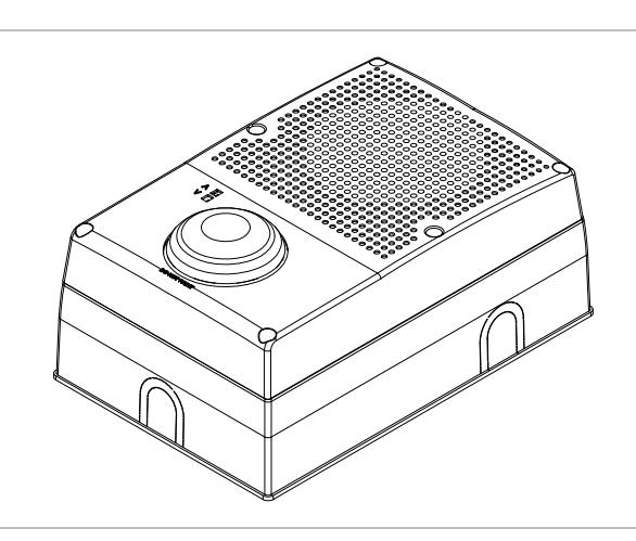
The Genesis WG4 High-Candela Speaker-Strobe is a fire alarm and mass notification and emergency communication (MNEC) appliance designed for indoor or outdoor wet location use on ceilings or walls. See Table 1 below for a list of models and Table 2 for a list of accessories.
The speaker-strobe includes field-configurable switches for setting speaker and strobe output levels. The settings are visible after final installation.
Table 1: Models
| Number | Description |
|---|---|
| WG4RF-SVMHC |
Outdoor-rated wall/ceiling speaker-strobe
(25/70 V), multi-tap, red with FIRE marking, 102/123/147/161 cd, clear lens |
| WG4RN-SVMHC |
Outdoor-rated wall/ceiling speaker-strobe
(25/70 V), multi-tap, red without marking, 102/123/147/161 cd, clear lens |
|
WG4WA-SVMHA [1] Outdoor-rated wall/ceiling speaker-clear-strobe
(25/70 V), multi-tap, white with ALERT marking, 84/101/125/130 cd, Amber lens |
|
| WG4WA-SVMHC |
Outdoor-rated wall/ceiling speaker-strobe
(25/70 V), multi-tap, white with ALERT marking, 102/123/147/161 cd, clear lens |
| WG4WF-SVMHC |
Outdoor-rated wall/ceiling speaker- strobe
(25/70 V), multi-tap, white with FIRE marking, 102/123/147/161 cd, clear lens |
|
WG4WN-SVMHA [1] Outdoor-rated wall/ceiling speaker-strobe
(25/70 V), multi-tap, white without marking, 84/101/125/130 cd, amber lens |
| Number | Description |
|---|---|
| WG4WN-SVMHC |
Outdoor-rated wall/ceiling speaker-strobe
(25/70 V), white without marking, 102/123/147/161 cd, clear lens |
[1] Only indoor strobes with a clear lens comply with the latest requirements of UL 1971 Signaling Devices for the Hearing Impaired .
Table 2: Accessories
| Number | Description |
|---|---|
| WG4WTS [1] |
Outdoor-rated surface skirt, white - for Genesis WG4
speaker or speaker/strobe |
| WG4RTS [1] |
Outdoor-rated surface skirt, red - for Genesis WG4
speaker or speaker/strobe |
| WGRGSKT | Appliance replacement gasket |
[1] The trim skirt is outdoor-rated when used with the 449 weatherproof box.
Synchronized operation requires a separately installed synchronization control module. See Table 3 on page 3 for a list of compatible synchronization sources.
Installation
Install this appliance in accordance with the latest edition of NFPA 72 and the local authority having jurisdiction.
WARNING: Electrocution hazard. To avoid personal injury or death from electrocution, remove all sources of power and allow stored energy to discharge before installing or removing equipment.
Caution: Electrical supervision requires the wire run to be broken at each terminal. Do not loop the signaling circuit field wires around the terminals.
Note: The Genesis WG4 High-Candela Speaker-Strobe may be ceiling-mounted or wall-mounted and may be placed in one of four positions (strobe above, strobe below, and strobe to either side); place the electrical box accordingly. See Figure 4.
To install the speaker-strobe:
- 1. Remove the cover from the speaker-strobe by first removing the six cover screws. See Figure 1 on page 2.
- 2. If desired, place the optional trim skirt over the electrical box. See "Specifications" for a list of compatible boxes.
- 3. Remove the gasket that comes with the 449 weatherproof box and replace it with the gasket that comes with the WG4 speaker-strobe.
- 4. Place the gasket over the backplate, and then feed the field wiring through the wire slots on the gasket and the backplate. See Figure 5, item 3.
- 5. Secure the backplate to the electrical box with four screws.
- 6. Connect the wiring to the terminal strip.
- 7. Connect the speaker to the audio NAC and the strobe to the strobe NAC. Observe polarity. See Figure 5.
- 8. If temporal strobe (private mode) operation is desired, cut jumper JP1. See Figure 5, item 5.
- 9. Set the speaker voltage.
The default speaker voltage is 70 V. For 25 V, reposition the speaker voltage-setting switch S3. See Figure 5, item 4.
10. Set the candela output.
The default candela setting is D. To select a different candela output, align the S2 indicator to the desired candela output. See Table 5 and Figure 5, item 1.
- 11. The default wattage setting is Z, corresponding to 1/4 watt. To select a different wattage, align the S1 indicator to the desired wattage setting. See Table 4 and Figure 5, item 2.
- 12. Remove the strobe protective cover. See Figure 2.
- 13. Position the cover over the backplate and secure with the six cover screws.
- 14. Test the unit for proper operation.
Figure 1: Exploded view of assembly
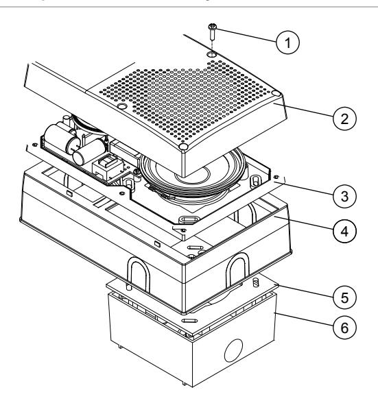
- 1. Cover screws (6X)
- 2. Front cover
- 3. Backplate
- 4. Optional skirt
- 5. Gasket
- 6. Electrical box
Figure 2: Protective cap
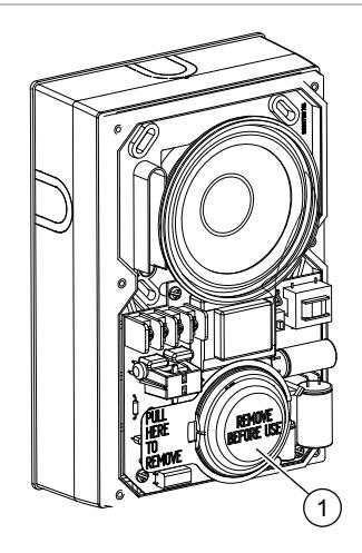
1. Protective cap
Figure 3: Assembled
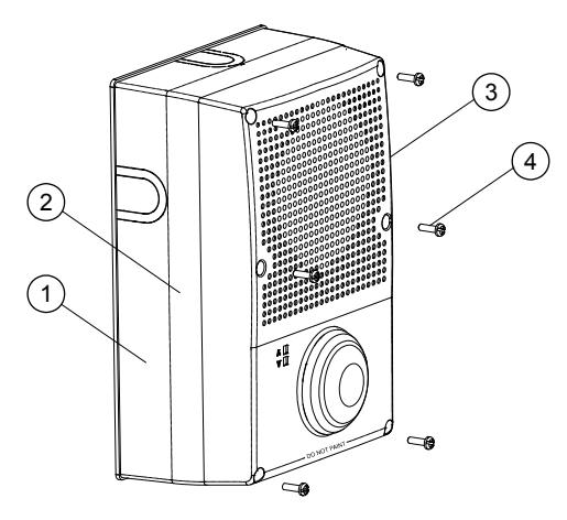
- 1. Optional skirt
- 2. Backplate
- 3. Front cover
- 4. Cover screws (6X)
Figure 4: Mounting positions
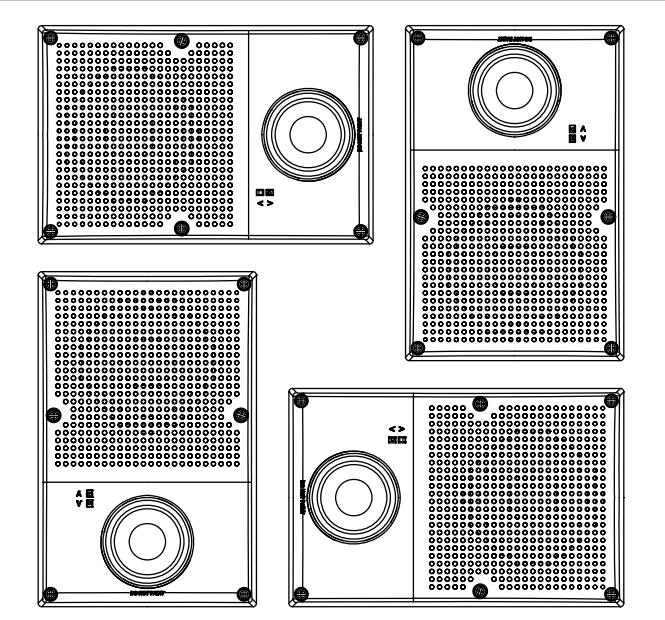
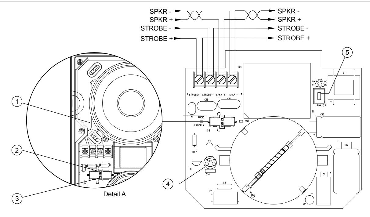
- 1. Wire slot.
- 2. S1 wattage-setting switch (see Table 4).
- 3. S2 candela-setting switch (see Table 5).
Note: Polarity shown in alarm condition
Maintenance
This unit is not serviceable or repairable. Should the unit fail to operate, contact the supplier for replacement.
Perform a visual inspection and an operational test twice a year or as directed by the local authority having jurisdiction.
Caution: Do not change the factory-applied finish.
Specifications
|
Operating voltage
Speaker Default Strobe |
25 VRMS or 70 VRMS, switch selectable
70 VRMS 24 VDC, 24 VFWR nominal |
|---|---|
| Supervisory voltage | 30 V max. |
| Sound level output | See Table 4 |
| Speaker response | 400 to 4,000 Hz |
| Strobe operating current See Table 8 | |
| Light output | Table 5, Table 6, and Figure 6 |
| Wire size | 12 to 18 AWG (0.75 to 2.50 mm²) |
|
Compatible electrical
box Wet Dry |
Model 449
4 in. square by 1-1/2 in. deep box |
|
Operating environment
Temperature Relative humidity |
Wet
−31 to 151°F (−35 to 66°C) 0 to 95% noncondensing |
- 4. JP1 strobe temporal mode selection jumper.
- 5. S3 speaker voltage-setting switch. UP position is 70 V (default); DOWN position is 25 V.
Table 3: Compatible synchronization sources models
| Name | Number | ||
|---|---|---|---|
|
Auto-Sync Output
Module |
SIGA-CC1S
GSA-MCC1S |
GSA-CC1S
SIGA-CC2A |
SIGA-MCC1S
SIGA-MCC2A |
|
Genesis Signal
Master Remote Mount |
ADTG1M-RM
MG1M-RM |
G1M-RM | EG1M-RM |
Table 4: Sound level output (dBA)
| Wattage | Setting | 25 V | 70 V | |
|---|---|---|---|---|
| 2 W | T | 90.0 | 89.7 | |
| 1 W | X | 87.1 | 86.9 | |
| 1/2 W | Y | 84.0 | 83.9 | |
| 1/4 W | Z | 80.8 | 80.8 |
dBA = Decibels, A-weighted.
UL 1480: Sound level output at 10 ft. (3.05 m) measured in a reverberant room using 400 to 4,000 Hz band-limited pink noise.
Table 5: Indoor strobe output (cd)
| Lens | Standard | D | C | B | A |
|---|---|---|---|---|---|
| Clear | UL 1971 | 102 | 123 | 147 | 161 |
| Amber | UL 1638 | 84 | 101 | 125 | 130 |
Table 6: Outdoor strobe output (cd)
| Lens | Standard | D | C | B | A | |
|---|---|---|---|---|---|---|
| Clear | UL 1638 | 41 | 50 | 60 | 65 | |
| Amber | UL 1638 | 34 | 41 | 51 | 52 |
| Lens | Rating (cd) |
|---|---|
| Clear | 233 nominal, 65 cd at −35°C |
| Amber | 188 nominal, 52 cd at −35°C |
Table 8: Strobe operating current in RMS (A)
| Setting | D | C | B | A |
|---|---|---|---|---|
| VDC | 324 | 390 | 494 | 495 |
| VFWR | 412 | 487 | 607 | 646 |
Figure 6: UL 1971 minimum light output (% of rating vs. angle)
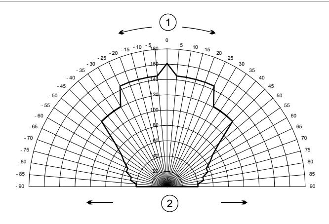
1. Angle
2. Percentage of rated output
Note: Horizontal plot
Regulatory information
| Manufacturer |
Edwards, A Division of UTC Fire & Security
Americas Corporation, Inc. 8985 Town Center Parkway, Bradenton, FL 34202, USA |
|
| Year of manufacture |
The first two digits of the DATE MFG
number (located on the product identification label) are the year of manufacture. |
|
| UL rating | Regulated 24 DC, Regulated 24 FWR | |
| Synchronization | Meets: UL 1971 requirements [1] | |
|
North American
standards |
Meets: UL 1971 [1], UL1638, UL1480
Follow: NFPA 72 |
|
| FCC compliance |
This device complies with part 15 of the
FCC Rules. Operation is subject to the following two conditions: (1) This device may not cause harmful interference, and (2) this device must accept any interference received, including interference that may cause undesired operation. |
|
|
Industry Canada
compliance |
This Class A digital apparatus complies with
Canadian ICES-003 |
|
[1] Only models with a clear lens meet UL 1971.
Contact information
For contact information see: www.utcfireandsecurity.com.