Edwards Signaling Installation Sheet Genesis Ceiling Speaker
Open the original PDF document
View PDFGenesis Ceiling Speaker
Product description
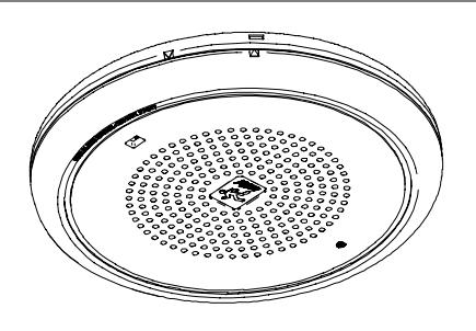
The Genesis Ceiling Speaker is an audible fire alarm notification appliance designed for indoor ceilings and walls. See Table 1 for a list of model numbers.
The speaker includes a field configurable switch for selecting the desired wattage tap. The wattage tap setting is locked in place and remains visible after final installation.
Install this device in accordance with applicable requirements in the latest editions of the NFPA codes and standards and Canadian Electrical Code, Part 1 , Section 32, and in accordance with the local authorities having jurisdiction.
Table 1: Models
| Description | Number | |
|---|---|---|
|
Speaker,
25 Vrms, white |
ADTGC-S2
EGC-S2 GC-S2 GC-S2-LG |
MGC-S2
XLSGC-S2 ZGC-S2 |
|
Speaker,
25 Vrms, white, with FIRE marking |
ADTGCF-S2
EGCF-S2 GCF-S2 GCF-S2-LG |
MGCF-S2
XLSGCF-S2 ZGCF-S2 |
|
Speaker,
70 Vrms, white |
ADTGC-S7
EGC-S7 GC-S7 GC-S7-LG |
MGC-S7
XLSGC-S7 ZGC-S7 |
|
Speaker,
70 Vrms, white, with FIRE marking |
ADTGCF-S7
EGCF-S7 GCF-S7 GCF-S7-LG |
MGCF-S7
XLSGCF-S7 ZGCF-S7 |
|
Speaker,
70 Vrms, red, with FIRE marking |
EGCFR-S7
GCFR-S7 MGCFR-S7 |
Specifications
Operating voltage: 25 Vrms (model S2), 70 Vrms (model S7)
Supervisory voltage: 30 V maximum Sound level output: See Table 2 Speaker response: 400 to 4,000 Hz
Wire size: 12 to 18 AWG (2.50 to 0.75 sq mm)
Compatible electrical boxes
North American 4 in square electrical box, 2-1/8 in deep (UL/ULC listed flush mounted with no extension ring)
Operating environment
Temperature: 32 to 120 °F (0 to 49 °C)
Humidity: 0 to 93% RH, noncondensing at 90 °F (32 °C) Agency listings: Meets ULC-S541 and UL 1480 fifth edition. Meets BS EN 60065:2002. Nameplate marking is located on the inside surface of the device.
Table 2: Sound level output (dBA)
| Wattage | 25V (UL) | 25V (ULC) 70V (UL) | 70V (ULC) | |
|---|---|---|---|---|
| 1/4 W | 80 | 78 | 80 | 81 |
| 1/2 W | 84 | 81 | 84 | 81 |
| 1 W | 87 | 87 | 87 | 87 |
| 2 W (UL) | 90 | 91 | ||
| 2.2 W (ULC) | 90 | 90 |
dBA = Decibels, A-weighted
UL 1480: Sound level output at 10 ft (3.05 m) measured in a reverberant room using 400 to 4,000 Hz band limited pink noise.
ULC-S541: Meets or exceeds 85 dBA in an anechoic chamber at 10 ft (3.05 m).
Directional characteristics: Within 6 dB of on-axis sound level when measured 90° off-axis (horizontal).
Installation instructions
Caution: Electrical supervision requires the wire run to be broken at each terminal. Do not loop the signaling circuit field wires around the terminals.
To install the speaker:
- 1. Remove the cover by depressing the tab on the side of the unit with a small screwdriver. Turn the cover counterclockwise to release.
- 2. Connect the speaker terminals to the signal circuit field wiring. You must observe polarity for the unit to function properly. See Figure 1.
- 3. Slide the wattage switch to the desired wattage tap (2 W, 1 W, 1/2 W, or 1/4 W) by aligning it with the indicator below the switch. See Figure 2.
- 4. Mount the unit onto a compatible electrical box. The switch selector position must be as shown in Figure 3.
- 5. Replace the cover by positioning the alignment arrows together and rotating the cover clockwise.
- 6. Test the unit for proper operation.
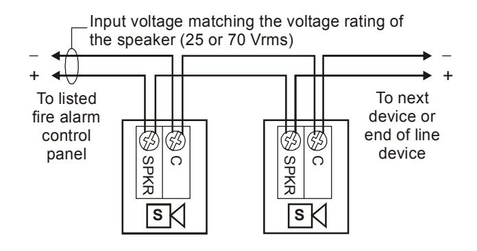
Figure 1: Wiring diagram
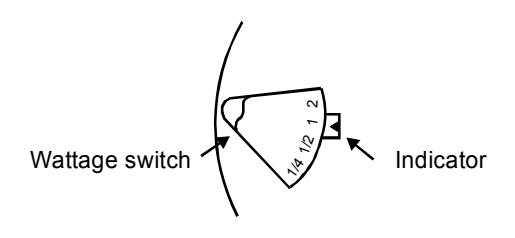
Figure 2: Wattage switch
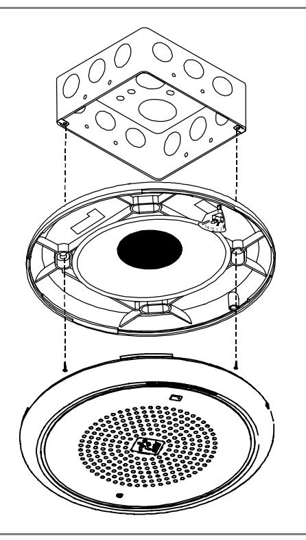
Figure 3: Mounting diagram (flush mounted electrical box)
Maintenance
This unit is not serviceable or repairable. Should the unit fail to operate, contact the supplier for replacement.
Perform a visual inspection and an operational test twice a year or as directed by the local authority having jurisdiction.