Edwards Signaling Installation Sheet 511C Smoke Detector
Open the original PDF document
View PDFESL 511/518 Series Smoke Detector Installation Instructions

Description
The ESL 511/518 Series Smoke Detector is a two-wire detector designed for use with a 24VDC fire system.
Refer to ESLs Compatibility Index for a complete listing of compatible control panels. For a copy of the Compatibility Index, call 1-800-648-7424.
! WARNING
It is important that you read, understand, and follow the instructions in this guide. If you have questions, call Sentrol at 1-800-648-7424.
This document is intended for licensed electricians/ alarm installers. Sentrol cannot provide technical support to unqualified persons.
Failure to properly install, test, and maintain a smoke detector system may cause it to fail resulting in loss of life and/or property.
The detector provides the following features:
Detector/base lock discourages unauthorized removal of the detector by requiring a screwdriver to remove the detector from the base.
Mounting base mounts directly to standard single-gang, 3 inch round or 4-inch octagonal electrical boxes. Can also be mounted directly to walls and ceilings if the local authority having jurisdiction allows.
Selecting a Location
Selecting a suitable location is critical to the operation of smoke detectors. This equipment should be installed in accordance with the National Fire Protection Associations (NFPA) Standard 72.
Important: Regulations pertaining to detector installation vary from state to state. For more information, contact your local fire department or local authority having jurisdiction.
In addition to NFPA 72, use the following location guidelines to optimize performance and reduce the chance of false alarms from the detector:
Locate ceiling-mounted smoke detectors in the center of a room or hallway at least 4 inches from any walls or partitions.
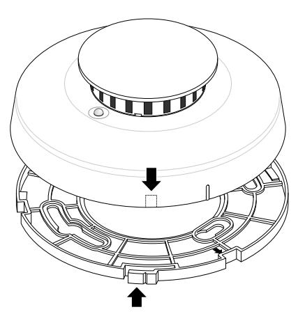
Figure 1 - Detector/Base Lock Knockouts
- Locate wall-mounted smoke detectors so the top of the detector is 4 to 12 inches below the ceiling.
- DO NOT locate detectors in or near bathrooms or kitchens.
-
Locate in a suitable environment as follows:
- Temperature between 32°F (0°C) and 100°F (37.8°C)
- Humidity between 0 and 95% non-condensing
- Locate away from air conditioners, heating registers and any other ventilation source that may interfere with smoke entering the detector.
- Mount smoke detectors on a firm permanent surface.
Installing the Detector
All wiring must conform to the National Electric Code (NEC) and/or local codes having jurisdiction. Use 12 to 24 AWG wire to install the detector.
- 1. If you are using the detector/base lock, remove the detector knockout and break off the tab on the mounting base. See Figure 1.
- 2. Remove the red plastic dust cover from the detector. The detector is shipped with a dust cover for protection on construction sites with dusty environments.
- 3. Run system wiring to the detector location and mount electrical boxes if necessary.
- 4. Line up and attach the gasket and mounting base to the electrical box, wall, or ceiling using the screws provided. Use the wall anchors if necessary. See Figure 2.
- 5. Strip the system wires and connect them to the appropriate terminals on the detector. See Figure 3.
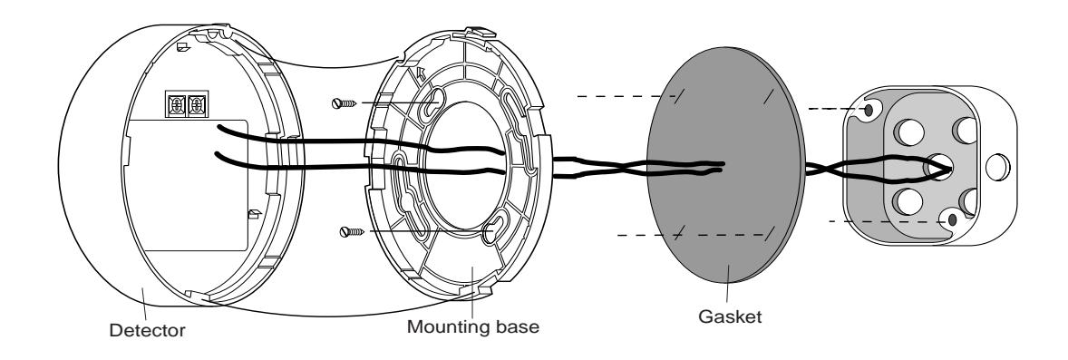
Figure 2 - Mounting the Detector
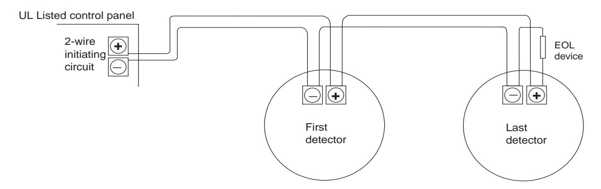
Figure 3 - Wiring Diagram
-
6. Attach the detector to the mounting base as follows:
- - Line up the raised tab on the side of the detector with the arrow on the mounting base. See Figure 4.
- - Insert the smoke detector into the base and turn clockwise approximately 15 degrees. It should snap firmly into place.
- 7. Apply power.
- 8. Test the detector. See Smoke Testing the Detector.
Important : The control panel alarm and all auxiliary functions should be verified for a complete test of the system.
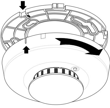
Figure 4- Attaching Detector to Base
Smoke Testing the Detector
Smoke detectors should be tested in place annually using smoke or canned aerosol simulated smoke. Follow the instructions on the canned smoke or use the following steps to test the detector with smoke:
- 1. Hold a smoldering punk or cotton wick close to the smoke entry openings.
- 2. Gently direct the smoke into the detector for 20 seconds or until an alarm is indicated.
BE SURE TO PROPERLY EXTINGUISH THE SMOKE SOURCE AFTER TESTING! The detector LED should stay on and an alarm should be indicated at the control panel. Use the system reset switch to reset the detector.
Understanding the LED
The LED on the detector indicates the status of the detector as follows:
Flashing every 9 seconds = Normal operation.
On = Detects smoke, sending an alarm.
Off or flashing once every 1.5 seconds = Trouble or maintenance is required. Test the detector. See Testing the Detector Sensitivity.
Testing the Detector Sensitivity
The detector provides a sensitivity test that allows you to check the detector sensitivity using a test magnet and the LED indicator on the detector as follows:
- 1. Hold the test magnet up to the raised TEST letters on the top of the detector for 2 seconds. See Figure 5. Once the test starts, the alarm LED flashes one to nine times.
- 2. Count the number of times the LED flashes and use the following table to determine the status of the detector sensitivity and what action to take, if any.
| Flashes |
Obscuration
(Approx) |
Indication | Action |
|---|---|---|---|
| 1 |
A N
/ |
Unserviceabl
e hardware fault detected. |
Reset unit and rerun
sensitivity test. If the error persists, replace the unit. |
|
2
-3 |
N
/ A |
Detector is no
t sensitive enough. |
Clean the unit. Reset unit
and rerun sensitivity test. If the error persists, replace the unit. |
| 4 | 3.6%/ft |
Detector is within
normal sensitivity range. |
N/A |
| 5 | 3.1%/ft | ||
| 6 | 2.6%/ft | ||
| 7 | 2.1%/ft | ||
|
8
-9 |
N
/ A |
Detector is to
o sensitive. |
Verify that the smoke
chamber is snapped down securely. Clean unit. |
After the test:
If the sensitivity is within limits and all other tests pass, the detector goes into alarm and must be reset from the control panel.
If the sensitivity is not within limits or an unserviceable hardware fault has been detected , the detector LED flashes every 1.5 seconds until the detector is serviced.
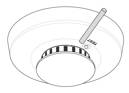
Figure 5 - Test Magnet Placement
Attaching and Removing the Detector
To remove the detector from the mounting base , grasp the detector and turn it counterclockwise approximately 15 degrees. The detector should snap off of the mounting base.
To remove the detector from the mounting base when the detector/base lock is used , insert a small screwdriver into the locking tab slot on the side of the base and press in while simultaneously turning the detector counterclockwise 15 degrees. See Figure 6.
Attach the smoke detector to its mounting base as follows:
- - Line up the raised tab on the side of the detector with the arrow on the mounting base. See Figure 4.
- - Insert the smoke detector into the base and turn clockwise approximately 15 degrees. It should snap firmly into place.
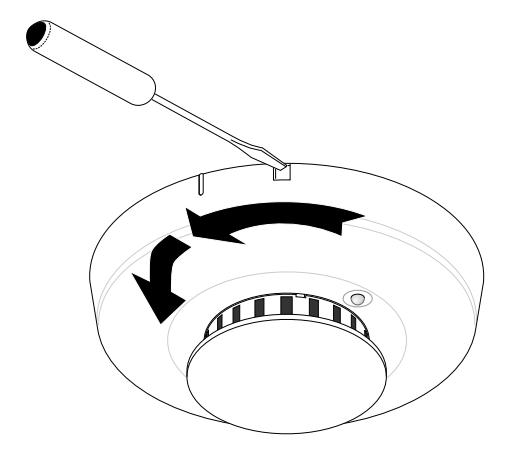
Figure 6 - Unlocking the Detector
Cleaning the Detector
Clean the detector cover with a dry or damp (water) cloth as needed to keep it free from dust and dirt.
When necessary, clean the detector interior and replace the optical chamber as follows:
- 1. Disconnect the alarm notification appliances, service release devices and extinguishing systems.
- 2. Slide a flat-blade screwdriver into the slot on the detector cap and gently push the handle down to pry the cap up and off. See Figure 7.
- 3. Press in on the sides of the optical chamber and pull it up and away from the detector and discard. See Figure 8.
- 4. Use a vacuum to remove dust and dirt from the optical chamber base.
- 5. Line the new optical chamber up with the optical chamber base and snap it down into place.
-
6. Replace the detector cap as follows:
- -Line the tabs on the cap with the slots on the detector.
- -Insert the cap into the smoke detector and turn clockwise approximately 15 degrees. It should snap firmly into place.
- 7. Test the detector sensitivity (See Testing the Detector Sensitivity).
- 8. Reconnect all alarm notification appliances, service release devices and extinguishing systems.
Important : The control panel alarm and all auxiliary functions should be verified for a complete test of the system.
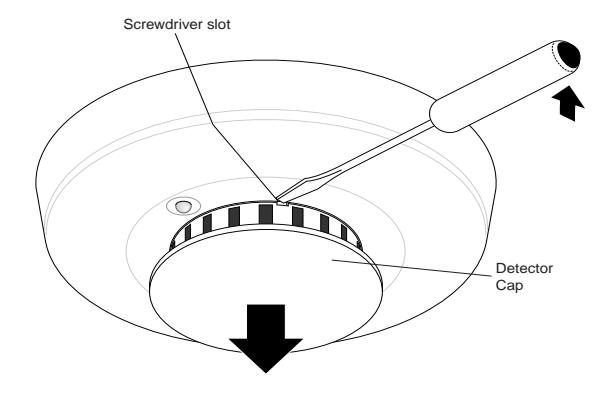
Figure 7 - Removing the Detector Cap
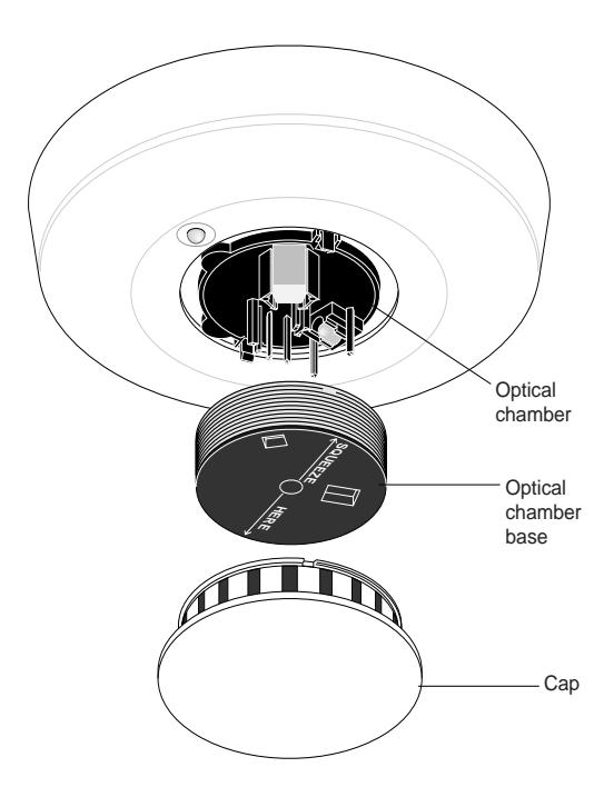
Figure 8 - Removing the Optical Chamber
Maintaining the Detector
The 511/518 Series smoke detectors are designed for easy field service and maintenance. When installed and used properly, they require minimal maintenance.
The smoke detector should be tested weekly. See Testing the Detector Sensitivity and Smoke Testing the Detector.
!
WARNING
Smoke detectors MAY NOT provide early warning for fires resulting from explosions, smoking in bed or other furniture, ignition of flammable liquids, vapors and gases, or children playing with matches or lighters.
Limited Warranty
ESL is a brand name of Sentrol. The manufacturer warrants this smoke detector to be free from defects in material and workmanship under conditions of normal use for a term of 3 years from the date of manufacture.
During the warranty period, if a Sentrol product or any of its components becomes defective, it will be repaired or replaced without charge.
Out-of-warranty units will be repaired at the discretion of the manufacturer, if not, a card will be forwarded to the customer suggesting a replacement unit and the cost of that unit.
This warranty does not apply to units which have been subject to environmental damage, abuse, misuse, negligence or accident, or to which any modifications, alterations or repairs have been made or attempted.
This warranty is extended only to the original purchaser of the smoke detector and may be enforced only by such person. During the warranty period, if the detector or any warranted components thereof becomes defective, at the manufacturers discretion, it will be replaced or repaired without charge if returned in accordance with the following instructions:
Obtain a Return Authorization Number by calling 1-800- 648-7422 or 503-692-4052, then carefully pack it in a well padded and insulated carton and return, postal charges prepaid to:
Customer Service Sentrol 12345 SW Leveton Drive Tualatin, OR 97062-9938
A note should be included advising the nature of the malfunction. Care must be exercised in the proper packing of detectors returned under this warranty as Sentrol will not be responsible for warranty repairs to equipment damaged because of improper packing.
THE ABOVE WARRANTY IS IN LIEU OF ALL OTHER EXPRESS WARRANTIES, AND IMPLIED WARRAN-
TIES OF MERCHANTABILITY AND FITNESS FOR A PARTICULAR PURPOSE ARE LIMITED IN DURATION FOR A PERIOD OF 3 YEARS FROM THE DATE OF MANUFACTURE. UNDER NO CIRCUMSTANCES SHALL MANUFACTURER BE LIABLE TO THE PUR-CHASER OR ANY OTHER PERSON FOR INCIDENTAL OR CONSEQUENTIAL DAMAGES OF ANY NATURE, INCLUDING WITHOUT LIMITATION DAMAGES FOR PERSONAL INJURY OR DAMAGES TO PROPERTY, AND HOWEVER OCCASIONED, WHETHER AL-LEGED AS RESULTING FROM BREACH OF WAR-RANTY BY MANUFACTURER, THE NEGLIGENCE OF MANUFACTURER OR OTHERWISE. MANUFACTURERS LIABILITY WILL IN NO EVENT EXCEED THE PURCHASE PRICE OF THE PRODUCT. SOME STATES DO NOT ALLOW LIMITATIONS ON HOW LONG AN IMPLIED WARRANTY LASTS, OR THE EXCLUSION OR LIMITATION OF INCIDENTAL OR CONSEQUENTIAL DAMAGES, SO THE ABOVE LIMITATIONS AND EXCLUSIONS MAY NOT APPLY TO YOU. UNLESS A LONGER PERIOD IS REQUIRED BY APPLICABLE LAW, ANY ACTION AGAINST MANUFACTURER IN CONNECTION WITH THIS SMOKE DETECTOR MUST BE COMMENCED WITHIN ONE YEAR AFTER THE CAUSE OF ACTION HAS OCCURRED.
No agent, employee or representative of the Manufacturer nor any other person is authorized to modify this warranty in any respect. Repair or replacement as stated above is the exclusive remedy of the purchase hereunder. This warranty gives you specific legal rights and you also have other rights which vary from state to state.
Specifications
| Voltage24VDC (8.5 - 33VDC), polarity sensitive | |
|---|---|
| Maximum standby current 70uA | |
| Maximum alarm current 70mA | |
| Minimum reset time1 sec | |
| Photoelectric sensitivity3.1% +0.5% -1% | |
| Operating temperature32°-100°F (0°-37.8°C) | |
| Operating humidity 0-95% non-condensing | |
| Colorwhite | |
| Packaging 10 detectors per carton |
| Detector dimensions 5" x 2" (12 cm x 5 cm) |
|---|
| Base dimensions4.75" x 0.3" (12.5 cm x 0.8 cm) |
| Drift compensation adjustment 1%/ft. max. |
| Heat detector specifications: |
| Rate of rise15°F/min>105°F (8.3°C/min>40.6°C) |
| Field wiring size12-24AWG |
| Listings: |
| 511C/511AFTUL 268 |
| 518C/518AFTULC |
| UL Compatibility identifierS10A |
Product Ordering
| Model | Description | ||
|---|---|---|---|
|
5
11C |
2-wire, photelectric detector UL, listed | ||
| 511AFT | 2-wire, photelectric detector w/ heat sensor, UL listed. | ||
|
5
18C |
2-wire, photelectric detector, ULC listed | ||
| 518AFT | 2-wire, photelectric detector w/ heat sensor, ULC listed. | ||
| Accessories | |||
|
4
01 |
Test magnet in a plastic shell for pole mounting | ||
| SM-200 | Smoke! in a Can canned smoke for functional testing. | ||
| SM-EXT 1 | Smoke! in a Can extension tube. | ||
|
2
11 |
Replacement optical chambers (set of 10) | ||

SENTROL
12345 SW Leveton Dr., Tualatin, OR 97062 Tel.: 503.692.4052 Fax: 503.691.7566
http://www.sentrol.com
FaxBack: 1.800.483.2495
U.S. & Canada: 800.547.2556 Technical Service: 800.648.7424
Sentrol reserves the right to change specifications without notice.
© 2000 Sentrol