Edwards Signaling Installation Instructions for 888D & 889D Horns
Open the original PDF document
View PDF

888D-N5 and 889D-AW Explosion-Proof AdaptaHorns Installation Sheet
Description
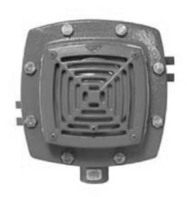
Edwards' explosion-proof AdaptaHorn signals, catalog numbers 888D-N5 and 889D-AW, are heavy-duty vibrating horns intended for use where distinctive audible signals are required in a hazardous location having high ambient noise levels.
These horns include a series diode and are suitable for use in fire alarm systems and other applications requiring electrical supervision of signal circuit installation wiring.
The 888D-N5 is AC-powered and the 889D-AW is DC-powered. They are UL Listed for indoor use in Class I, Groups B, C, and D; Class II, Groups E, F, and G; and Class III locations, for both Divisions 1 and 2.
Installation
The following items (not supplied) are required for installation of the horn:
- 3/4 in. conduit to contain power supply wires.
- One explosion-proof conduit outlet box suitable for use in the hazardous location.
- One 3/4-14 National Pipe Taper (NPT) nipple.
- Two fasteners up to 3/8 in. diameter and washers suitable for securing the horn to mounting surface. The horn can be mounted to any solid surface.
WARNING: Electrocution hazard. Do not apply power to the horn until installation has been completed and cover has been secured on outlet box.
To install the horn:
-
1. See Figure 1. Remove the cover from the conduit outlet box. Feed the two power supply wires from control panel or previous signal and the two wires to next signal or endof-line device through conduit into the outlet box.
- Also, feed the horn's three power connection wires through the nipple, which connects the horn to the outlet box, into the box. Secure the horn and conduit to the outlet box.
- 2. With the horn placed against mounting surface, mark mounting hole positions for fasteners as per Figure 1. Install fasteners with washers through mounting brackets and secure unit to surface.
- 3. Make the required power supply wiring connection and make wiring connection to next signal or end-of-line device in outlet box. For 888D-N5, see Figure 2. For 889D-AW, see Figure 3.
- 4. Apply power to the fire alarm control panel. Initiate an alarm to activate the horn and verify that it sounds. Then reset the panel and verify that the horn silences.
Figure 1: Signal mounting details
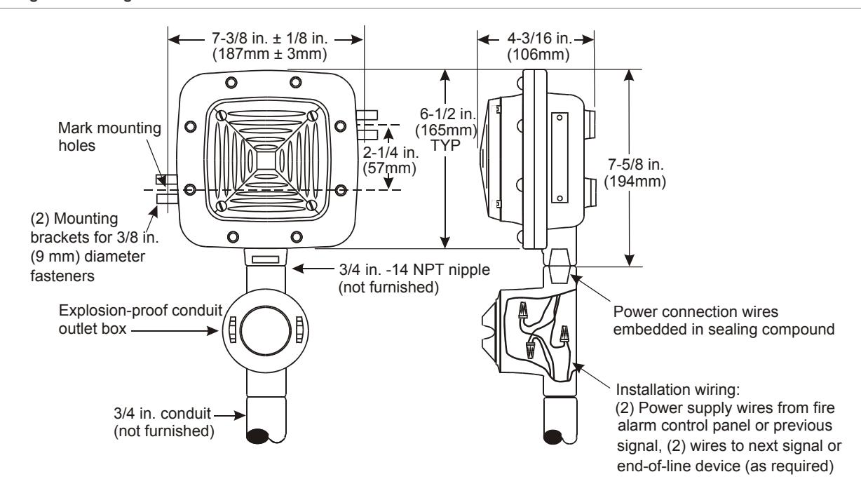
Figure 2: 888D-N5 - Fire alarm system use or other applications requiring a supervised signaling circuit
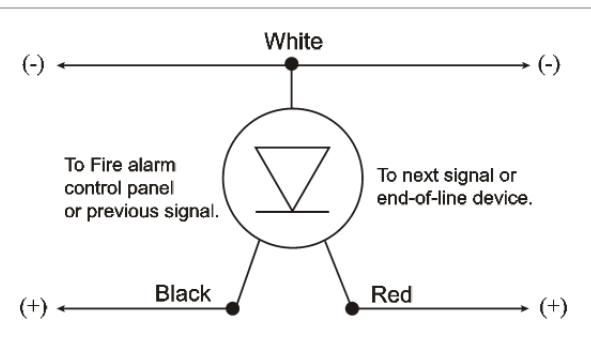
Note: Supervisory DC voltage polarity is shown. On alarm, the voltage switches to 120 VAC.
Figure 3: 889D-AW - Fire alarm system use or other applications requiring a supervised signaling circuit.
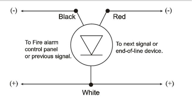
Note: Supervisory DC voltage polarity is shown. On alarm, the polarity reverses.
Maintenance
Examine the horn annually for accumulation of dirt and clean if necessary. Test the horn annually or at the intervals required by applicable fire regulations.
Electrical specifications
|
Catalog
number |
Rated
voltage |
Alarm
current |
dBA rating
(anechoic )[1] |
dBA rating
(reverb.)[2] |
|---|---|---|---|---|
| 888D-N5 | 120 VAC | 0.165 A | 100 | 90 |
| 889D-AW | 20 - 24 VDC | 0.16 A | 97 | 84 |
[1] dBA rating at 10 ft., typical rating measured in an anechoic chamber. Sound level rating as measured with "A" weighted scale.
[2] dBA rating at 10 ft. per UL 464; sound level output rating measured in a reverberant room. Sound level rating as measured with "A" weighted scale.
Regulatory information
| Manufacturer |
Edwards, A Division of UTC Fire & Security
Americas Corporation, Inc. 8985 Town Center Parkway, Bradenton, FL 34202, USA |
|---|---|
|
North American
standards |
UL 1203 |
Contact information
For contact information, see www.edwardssignaling.com.