Edwards Signaling Installation Instructions for 5532MD Speaker Amplifier
Open the original PDF document
View PDF

5532MD Series Adaptatone Speaker-Amplifier Installation Sheet
Description
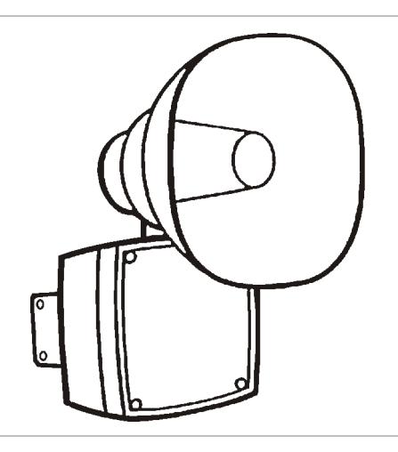
The 5532MD Series Adaptatone Speaker-Amplifier is a UL and cUL Listed audible signal appliance that is designed to accept system audio input levels of 10 VRMS (5532MD-10AW) or 70 VRMS (5532MD-70AW), making it possible to interface to public address systems where area-wide system audio is required. The units are also diode polarized for use in fire alarm applications.
Additionally, the 5532MD Series units are UL and cUL listed for use in the hazardous locations shown in Table 1.
The speaker-amplifier is a heavy-duty, stand-alone signaling device that operates from local power and sounds a tone programmed at the tone generator. The speaker direction and output level are easily adjustable.
This equipment is suitable for use in Class I, Division 2, Groups A, B, C, and D; Class II, Division 2, Groups F and G; and Class III hazardous locations or nonhazardous locations.
Installation
Install and wire this device in accordance with applicable national and local codes, ordinances, and regulations.
When the signal is used in a fire protective signaling system, you must install it in accordance with these instructions, and with the applicable requirements of NFPA 70 and 72 in the US or CAN/ULC-S524 and CSA C22.1 in Canada.
When the device is used in general signaling applications, you must install it in accordance with these instructions, and with the applicable requirements of NFPA 70 in the US or CSA C22.1 in Canada.
When the device is used in Division 2 applications, you must install it in accordance with the NFPA 70 Article 501-4b.
The Adaptatone can be mounted on any flat surface or can be used as a freestanding unit mounted on a rigid pipe. The Adaptatone must be installed by a trained and qualified electrician.
WARNINGS
- Explosion hazard. Do not disconnect equipment unless power has been removed or the area is known to be nonhazardous.
- Explosion hazard. Substitution of any components may impair suitability for Class I, Division 2.
- To ensure the integrity of the Adaptatone assembly when adjusting the speaker direction, make sure threads in the enclosure remain fully engaged and do not turn speaker more than 360 degrees from the original factory installed position.
- To prevent fire, shock and component damage, no work , including circuit board removal, should be performed while the circuit is energized.
- High voltage is present when product is energized.
- High volume may cause harm to personnel in close proximity.
- To ensure the integrity of the enclosure: Make sure that the cover gasket, P/N P-007549-0069, is adhered into the groove at the cover perimeter before replacing the signal box cover.
- Ensure that the four collar gaskets, P/N P-041930-0362, are in place on each cover screw before securing the signal box cover.
- When securing the cover, start the screws by hand, making sure that they are threaded into the tapped holes in the housing bosses before securing them with a screwdriver. Torque the signal box cover screws to a minimum of 20 in-lbs. This ensures the required tight fit.
Caution: During installation, care must be taken so that components on the printed circuit board are not damaged.
Notes
- Any kind of service or maintenance performed while unit is energized will void the warranty.
- The increased resistance due to long wire runs needs to be accounted for in sizing wire. Consult Applications Engineering for details.
To install the Adaptatone:
1. Mount Adaptatone as shown in Figure 1.
Flat Surface mounting: Secure the unit to the mounting surface using the four mounting holes in the mounting plate on the rear of the box. Use the #10 x 3 wood screws (furnished loose) or other hardware (not supplied) suitable for the mounting surface.
Rigid Pipe mounting: Loosen the four cover screws from the signal box and lift off the signal box cover.
Note: The cover screws are captive. Do not remove them from the cover.
Remove the center knockout in lower wall of the box and mount the box on a 1/2 in. conduit pipe using a suitable connector.
- 2. Wire in accordance with the instructions in "Wiring" on page 2.
- 3. Adjust the volume level, if desired, by turning the potentiometer located on the main board (Figure 6).
- 4. Tightly secure the signal box cover using the four retained cover screws.
- 5. Torque the signal box cover screws to a minimum of 20 in-lbs.
- 6. To adjust the speaker direction, the loosen large star nut (Figure 1) and turn the speaker to the approximate desired position
Regardless of the speaker direction adjustment, it is important that the star nut be tightened wrench-tight to ensure the speaker position is maintained securely.
7. Verify operability.
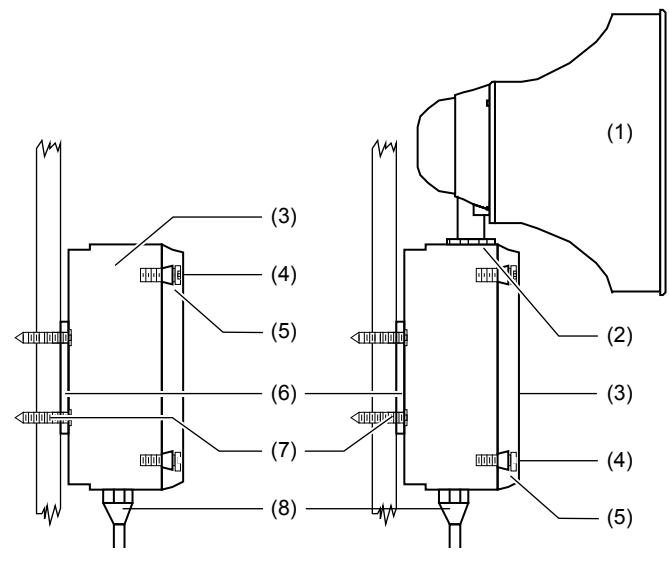
- (1) Speaker
- (2) Large star nut to adjust speaker direction
- (3) Signal box
- (4) Cover screws (4X)
- (5) Collar gaskets (4X)
- (6) Mounting plate
- (7) #10 × 3 screws or hardware suitable for the mounting surface
- (8) Raceway and connections (not supplied) to 1/2 in. knockout hole
Wiring
WARNING: To prevent fire and shock, wire the Adaptatone only as described in this installation instruction.
Caution: Risk of system failure. Electrical supervision requires that the wire run be broken at each terminal. Do not loop the field wires around the terminals.
Note: Terminal Block TB1 can be unplugged from the main board to complete wiring as shown in Figure 2.
To wire the Adaptatone:
- 1. Install wires through a knockout hole in the bottom of the box from a raceway that is, with its connections to the 1/2 in. conduit knockout hole, approved for the same degree of protection and enclosure type needed by the application. Use the plastic cable ties, on the barrier to the electronics, to separate incoming power leads from signal and tone initiating leads, per NEC (Figure 4).
-
2. Wire as follows referring to Figure 4.
- a. Connect the green and yellow striped earth ground wires to earth ground.
- b. See Figure 4 and Figure 5. Connect the audio in (+) and (−) to the AUD (+) and (−) terminals (respectively) on the speakeramplifier audio coupler board. Use shielded cable and connect the braid or drain to the earth ground wire on the unit.
- c. Connect wires leading to the next signal or end-of-line resistor to TB1 terminals 1 and 2 on the main board as shown in Figure 3. Polarity must be observed.
- d. Optional. Connect an external 24 VDC battery (not supplied) in series with the separate diode assembly (P/N 2600010, supplied) to TB1 terminals 3 and 4 on the main board as shown in Figure 3 and marked on the diode assembly.
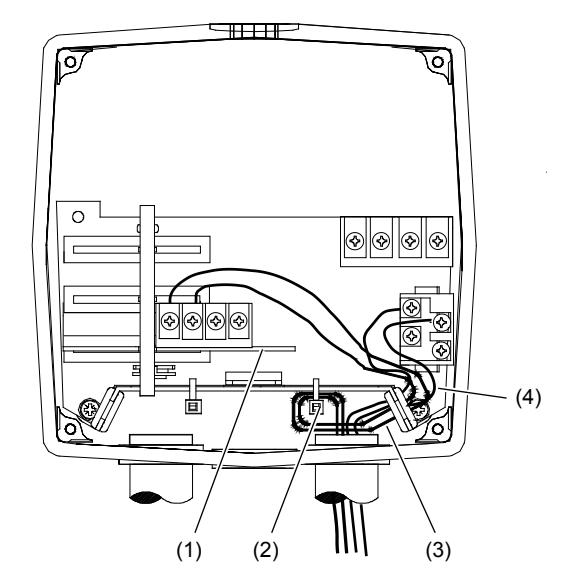
Figure 2: Terminal block TB1
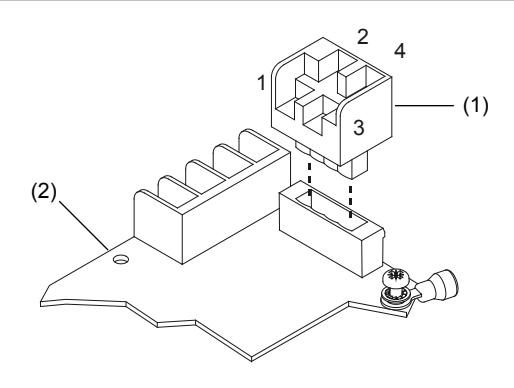
- (1) Terminal block (TB1) (2) Main board
Figure 3: Wiring to terminal block TB1
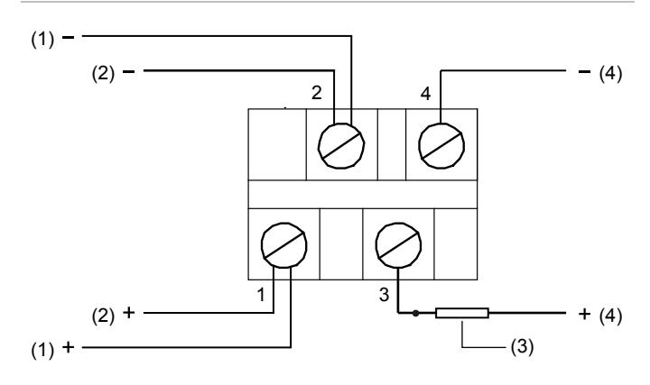
- (1) To next signal or end-of-line resistor
- (2) From control panel signal circuit
- (3) Diode assembly P/N 2600010 (4) To optional 24 VDC battery backup
Note: Polarity is shown in the alarm condition. The polarity is reversed in the field wire monitoring the condition of the control panel.
Figure 4: Wiring the 5532M series speaker-amplifier
- (1) Audio coupler board
- (2) Plastic cable ties (provided) used to separate power leads from signal and tone initiating leads
- (3) Signal leads to be connected to the audio coupler board as applicable
- (4) +24 VDC wiring from the fire alarm control panel (FACP)
Figure 5: Wiring audio output of FACP to speaker-amplifier audio coupler board
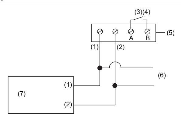
- (1) AUD (Audio) +
- (2) AUD (Audio) −
- (3) Relay
- (4) Power supervision (where applicable)
- (5) Audio coupler board
- (6) To other speaker-amplifier audio coupler boards
- (7) Tone generator
Figure 6: 5532M Series PC board locations
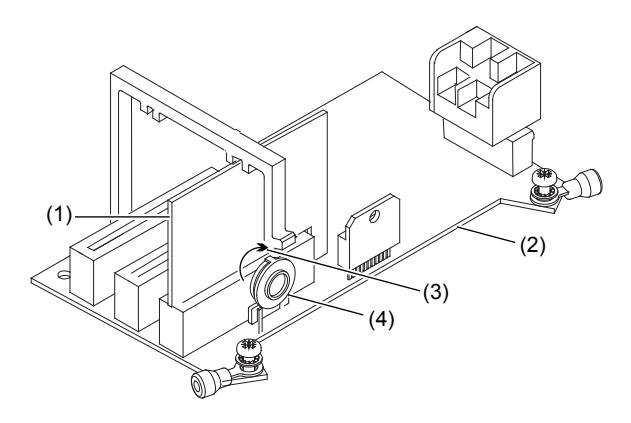
- (1) Audio input board
- (2) Main board
- (3) Direction of increasing volume
- (4) Potentiometer for volume adjustment
Maintenance and testing
WARNING: To prevent fire, shock and component damage, no work , including circuit board removal, should be performed while the circuit is energized. Ensure that power is disconnected before cleaning the inside of the unit.
Note: Any kind of service or maintenance performed while unit is energized will void the warranty.
Examine the unit semiannually for accumulation of dirt. Clean it if necessary.
The Adaptatone should be tested annually or as required by the authority having jurisdiction to ensure continuous service.
Specifications
| Voltage | Refer to Table 2 |
| Current | Refer to Table 2 |
| Dimensions | Refer to Table 3 |
| Weight | 9 lb. (4.1 kg) |
|
Hazardous locations [1]
Ambient temp. |
−31 to 104°F (−35 to +40°C) |
|
Nonhazardous locations
Variable ambient temp. |
−40 to 151°F (−40 to +66°C) |
[1] Hazardous locations and variable ambient conditions apply only where UL Listings are accepted.
Table 1: Hazardous locations
| Model number | Hazardous location | Temperature code |
|---|---|---|
|
5532MD-10AW
5532MD-70AW |
Class I, Div. 2,
Groups A, B, C, D |
T3C (160°C, 320°F) |
|
Class II, Div. 2, Groups F, G
Class III |
T5 (100°C, 212°F) |
Table 2: Electrical specifications
| Voltage | Current (tone on) | |
|---|---|---|
| 20 VDC | 0.63 A | |
| 24 VDC | 0.74 A | |
| 28 VDC | 1.0 A | |
| 31 VDC | 0.85 A | |
| 20 VFWR 120 Hz | 0.69 A | |
| 24 VFWR 120 Hz | 0.79 A | |
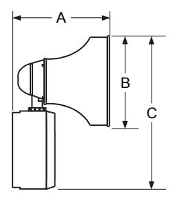
Table 3: Speaker-amplifier dimensions
| 5532M | |
|---|---|
| A | 8-7/8 in. (225 mm) |
| B | 8-1/4 in. (210 mm) |
| C | 13 in. (330 mm) |
Regulatory information
| Ratings | ANSI/ISA 12.12.01 | |
| CAN/CSA C22.2 No. 25 | ||
| CAN/CSA C22.2 No. 213 | ||
| NEMA Type 3R | ||
| UL 464 | ||
| UL 1480 |
Contact information
For contact information, see www.edwardssignaling.com.