Edwards Signaling INT-22.5R1-24 Installation Instruction
Open the original PDF document
View PDF

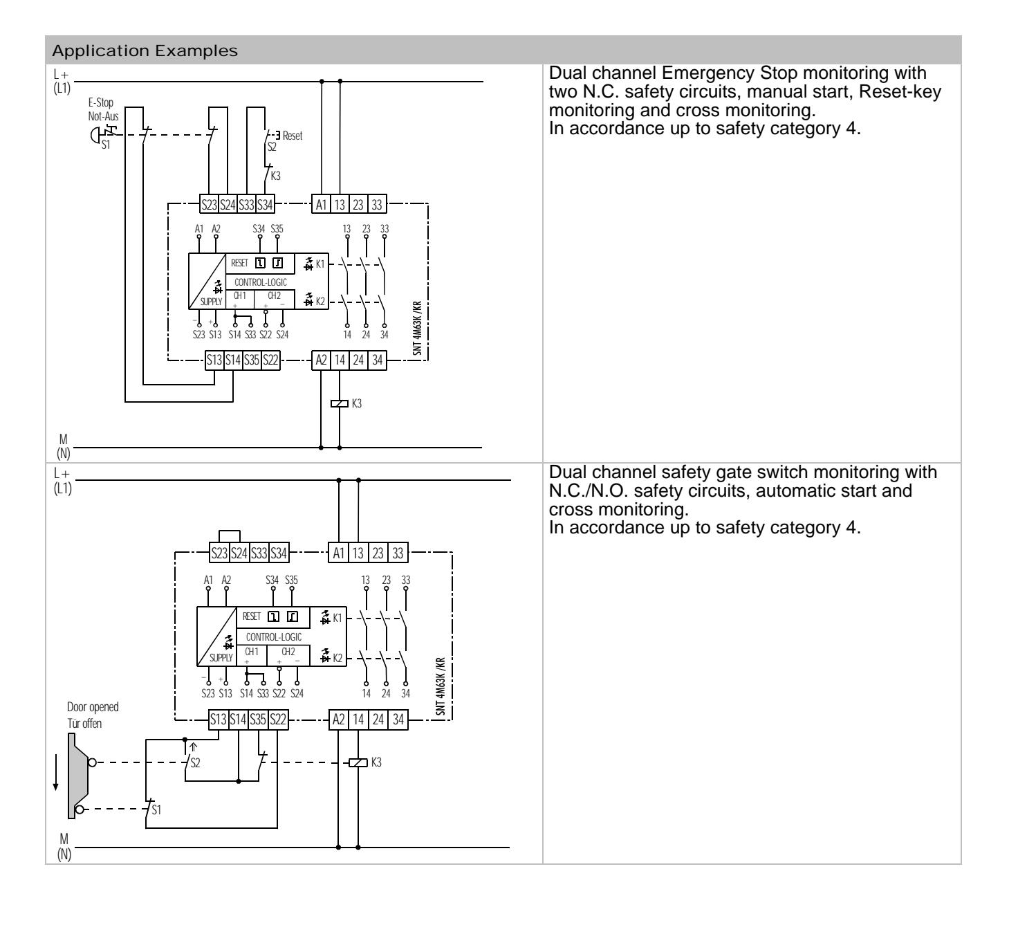
Base Device for Emergency Stop and Safety Gate Applications
- Basic device to EN 60204-1 and EN 954 1
- Safety category 4 to EN954-1
- Stop category 0 to EN 60204-1
- Manual or automatic start
- Cross monitoring
- Feedback circuit for monitoring external contactors
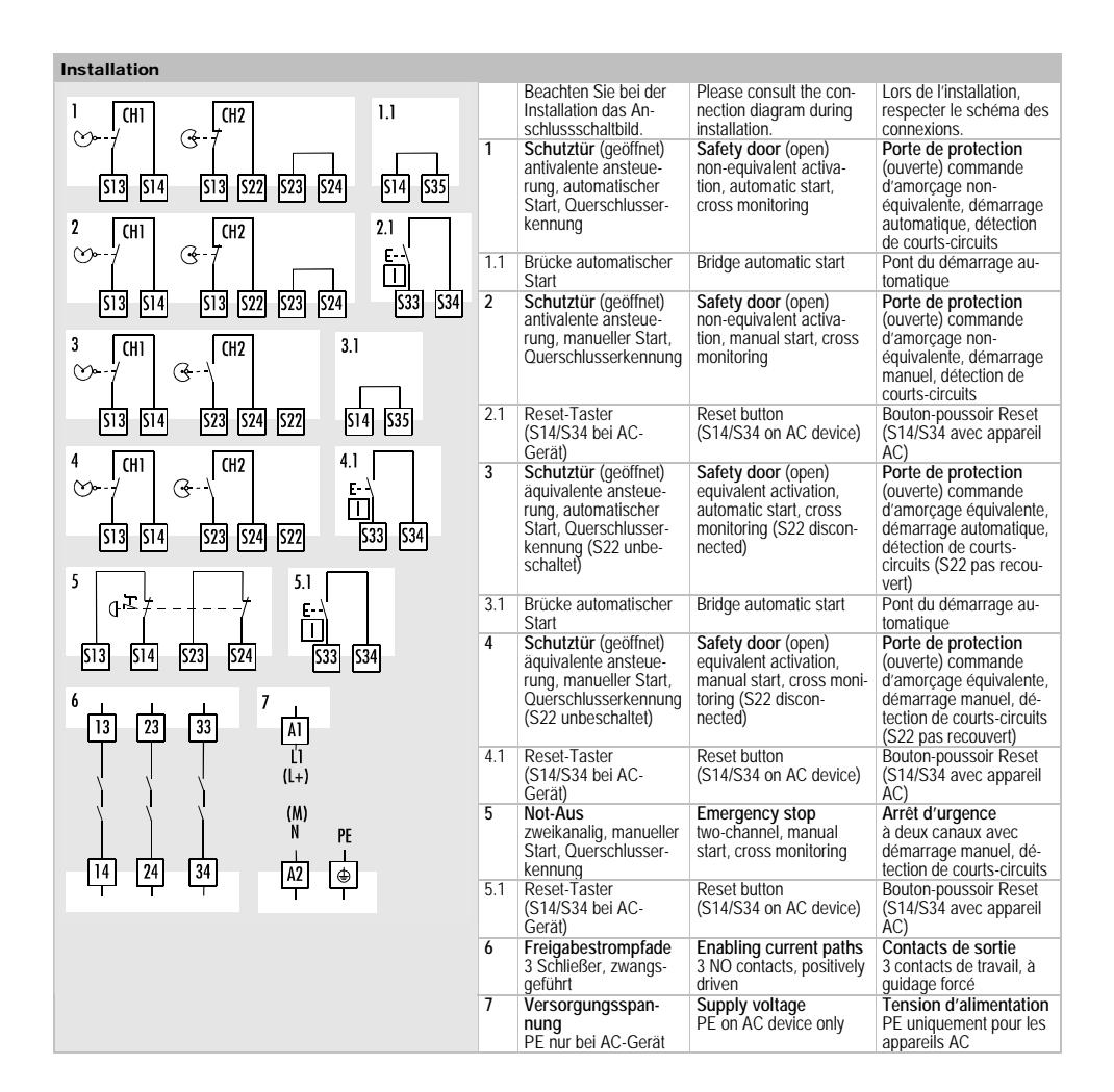
- 3 enabling current paths
- Equivalent and non-equivalent activation
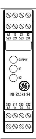
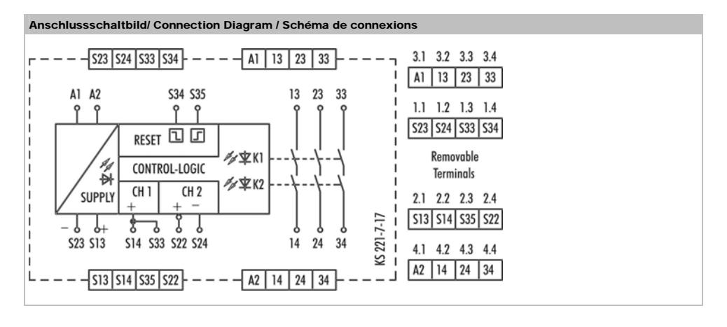
Front View
SUPPLY LED green Power Supply K1 LED green Relay K1 K2 LED green Relay K2

Safety Instructions
Only trained professional electricians may install, startup, modify, and retrofit this equipment! Disconnect the device / system from all power sources prior to starting any work! If installation or system errors occur, line voltage may be present at the control circuit in devices without DC isolation! Observe all electrical safety regulations issued by the appropriate technical authorities or the trade association. The safety function can be lost if the device is not used for the intended purpose. Opening the housing or any other manipulation will void the warranty.

Caution!
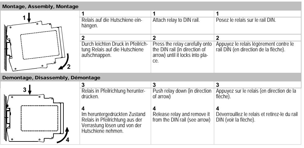
Perform the following precautionary steps prior to installation, assembly, or disassembly:
- 1. Disconnect supply voltage to the equipment / system prior to starting any work!
- 2. Lockout/tag the equipment / system to prevent accidental activation!
- 3. Confirm that no voltage is present!
- 4. Ground the phases and short to ground!
- 5. Protect against adjacent live components using guards and barriers!
- 6. The devices must be installed in a cabinet with a protection class of at least IP 54.

Caution!
Limited contact protection! Protection type according to DIN EN 60529. Housing/terminals: IP 40/ IP 20. Finger-proof acc. to VDE 0660 Part 514.
Description of Device and Function
This device is a two-channel safety switching device with self-monitoring on each ON-OFF cycle. It conforms to EN 60204-1 and is equipped with positively driven relays. It is intended for monitoring connected switching elements on separating safety devices and generating a safetyoriented output signal (enable). Depending on the design, separating safety devices may include protective screens, safety doors, enclosures, covers, screens, etc.
Basic function: After supply voltage has been connected to terminals A1/A2 and the safety inputs closed, operating the reset button closes the enabling current paths (manual start). When the safety inputs are opened the enabling current paths will open.
Operating modes / system functions
- Two-channel activation The device uses two-channel activation. With equivalent activation safety channel CH1 is connected via positive potential, safety channel CH2 via negative potential. With non-equivalent activation both safety channels are connected to positive potential.
- Cross monitoring With equivalent activation cross monitoring is achieved by means of the short-circuit principle; with non-equivalent activation it is achieved through functional diversity.
- Manual start When the safety inputs are closed, a button is used to close reset input S34 and then open it again (triggering with falling edge) or to close reset input S35 (triggering with rising edge).
- Automatic start Reset input S35 is connected to S33/S14. The device starts with the rising edge of the signal on safety input S14.
- Starting lockout After supply voltage has been connected and the safety inputs closed, the enabling paths will not close. Starting is only possible after the reset button has been operated. For starting lockout the reset inputs have to be activated with the button, as in manual start mode.
- Restarting lockout No restart after the safety inputs have been opened and closed. Restarting is only possible after the reset button has been operated. For restarting lockout the reset inputs have to be activated with the button, as in manual start mode.
- Synchro-check Synchro-check is only possible in automatic start mode (bridge S33/S14 S35). After safety channel CH1, safety channel CH2 must close (S24) or open (S22) within the synchronous time tS. If CH2 closes or opens before CH1, the synchronous time tS = ∞ .
Please observe instructions from safety authorities.
Proper Use
The devices are safety switching devices. They must only be used as components of safety equipment on machines intended to protect persons, material and plant.
Notes
- The safety category acc. to EN 954-1 depends on the external circuitry, the choice of control devices and their location on the machine.
- The indicated times must be observed when the device is operated, otherwise the device could lock. Locking can be cancelled by opening the safety inputs properly.
- SNE expansion devices or external contactors with positively driven contacts can be used to duplicate the enabling current paths.
- The device and the contacts must be protected at max. 6 A utilization category gG.
- The devices are equipped with overload protection (for short-circuit). After the malfunction has been dealt with, the device is operational again in approx. 3 s.
- Control output S13 is exclusively for connecting control devices as defined in the operating instructions and not for connecting external consumers such as lamps, relays or contactors.
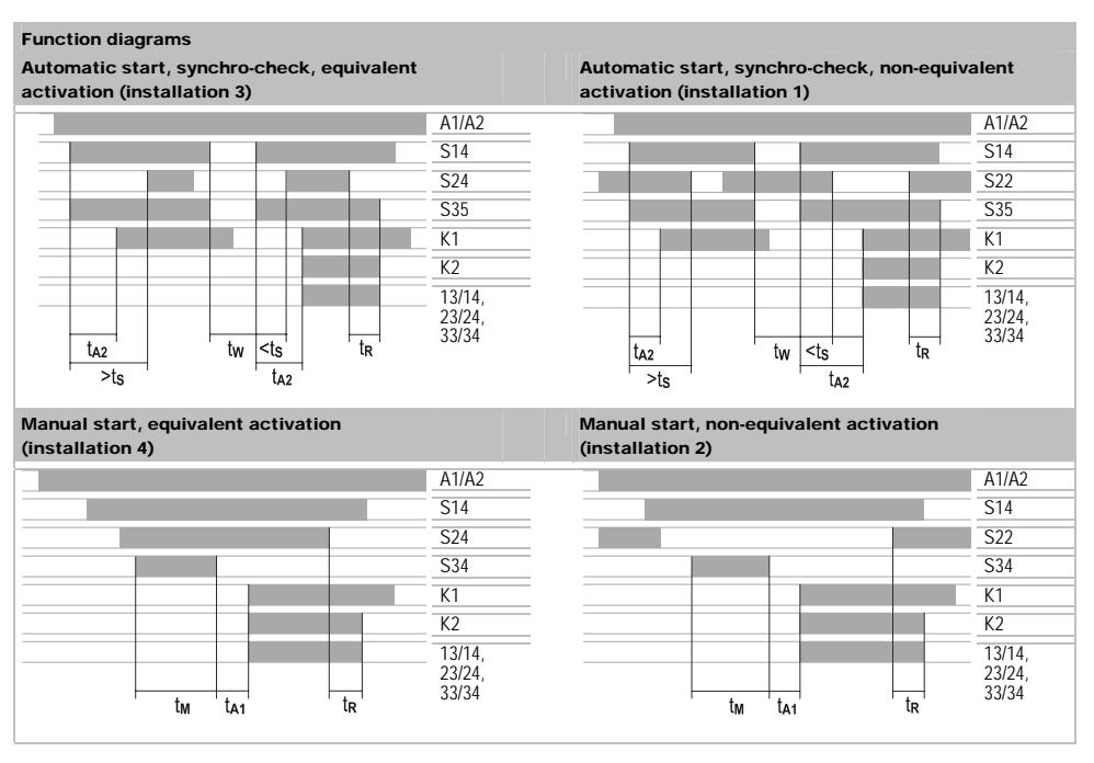
tM = Min. ON time
tA1 / tA2 = Operate time
tS = Synchronous monitoring time
tW = recovery time
tR = release time
|
hn
ic al d T at ec a Po ir it w er c cu ry Ra te d lta U vo ge N Ra d D C te po w er Ra te d A C po w er Re sid l r ip le US ua p S d fre Ra te qu en cy O tin lta pe ra g vo ge ra ng e Pr tio fo l c irc ui ly ot tro t s ec n r c on up p C tr ol ir it on c cu O ut ts S 13 , S 23 pu Ra d ol S 13 , S 23 te tp ut ta ou v ge No -lo ad ol ta A C de vi v ge ce O ut t c nt pu ur re Sh irc ui of / li itin t-c t-p nt or ro cu rre m g In ts S 14 /S 33 , S 22 , S 24 , S 34 , S 35 pu ol ( fo l s In t v ta xt pu ge ra ng e r e er na up / /S Ra te d nt ak nt S 14 cu rre pe c ur re Ra d / ak S 34 , S te nt nt cu rre pe c ur re Ti m es Pe iss ib le ul ti / te st tTP te st rm p se m e O te ti tA1 S3 4 pe ra m e O ti S3 5 te tA2 pe ra m e O ti te tA3 pe ra m e M in . O N tim tM S 34 , S 35 e Sy hr tim C H1 b ef C tS nc on ou s e or e Re ti tW co ve ry m e Re le tim K1 , K 2 tR as e e |
ly,
nly DC d ice s) p o o n ev 33 , S 22 , S 24 35 fr eq ue nc y H2 |
/D
AC C 24 V, A C 11 5 12 0 V, A C 23 0 V – 2. 0 W / 2. 6 W 3. 2 VA 2. 4 V 50 60 H z 0. 85 1. 1 UN x Sh irc ui of ( DC d ice P TC th ist / AC d ice ho ci ui of t-c t-p rt- t-p or ro ev s: er m or ev s: s rc ro ) tra fo ns rm er DC 2 2 V 40 V < 10 0 A m / N Ye s o DC C 1 7. 4 V to D 26 .4 V / 1 40 A 00 A m m A / 5 0 A 5 m m 10 00 / ≤ 1 0 s-1 ≤ s µ 20 to 4 0 m s m s 20 0 6 00 to m s m s 10 0 to 4 00 m s m s 80 m s > |
|---|---|---|
|
. 2
00 ap pr ox m s 10 0 ≥ m s |
||
|
25
m s < |
||
|
O
ci ui ut t t pu rc |
||
|
En
ab lin th g pa s |
||
|
Co
nt t e ip t ac qu m en |
3
NO ta ct itiv el dr ive c on s, p os y n |
|
|
Ra
d itc hi ol U te ta sw ng v ge n |
AC
2 30 V / DC 3 00 V |
|
|
M
tin nt In nt at h ax . c on uo us c ur re p er c ur re p |
6
A |
|
|
M
al fo ll AC . t ot nt ax cu rre r a |
/D
C 24 V |
12
A |
|
hs
nt at AC cu rre p |
C
1 15 12 0 V, A 23 0 V - |
8
A |
|
Ut
iliz io di IE C at te to n ca go ry a cc or ng |
94
7 - 5 - 1 |
(
1) ( ) AC -1 5: U 23 0 V, Ie 4 A 36 0 h- DC -1 3: U 24 V , I 4 A 36 0 h-1 e e e |
|
AC
U 23 V, Ie 3 A ( 36 h -1) D C 3: U 24 V , I 2, A ( 36 h -1) -1 5: 0 00 -1 5 00 e e e |
||
|
M
ha ni l s vi lif ec ca er ce e |
10
x1 06 itc hi le s w ng c yc s |
|
|
G
al d at en er a e/ Cl d ist b et ea ra nc cr ee an ce w ee |
cir
its n cu |
EN
6 09 47 -1 :1 2. 99 |
|
pa
ge O ol ta at |
III | |
|
ve
rv ge c eg or y Ra te d im lse ith st d lev el w an |
4
kV |
|
|
pu
Co in io lev el of d ice : i id nt at am n ev ns |
/ o
sid ut e e |
2
/ 3 |
|
Ra
te d lta vo ge |
30
0 V |
|
|
Po
-fr ol te st ta w er eq ue nc y v ge |
2
kV |
|
|
tio
cla Pr ot to D IN V DE 0 47 0 Pa ec n ss |
h
si / in al rt 1: te ou ng rm s |
/ I
IP 4 0 P 20 |
|
Am
bi t / to te tu en s ra ge m pe ra re |
-2
5 55 ° C / - 25 +7 5 °C + |
|
|
Cl
im ic lic io cla at at ap p n ss |
H V G D IN 87 to 4 00 40 : 0 4: |
|
|
W
ei ht DC g |
d
ice ev |
0.
21 k g |
| AC |
d
ice ev |
0.
25 k g |
|
T
in al d ti er m s an co nn ec on |
||
|
Si
le fi nd ed |
² t
2. ² 2 ² t ² 1 0. 14 5 0. 14 0. 75 |
|
|
ly
st ng -c or e or ne ra St in le th |
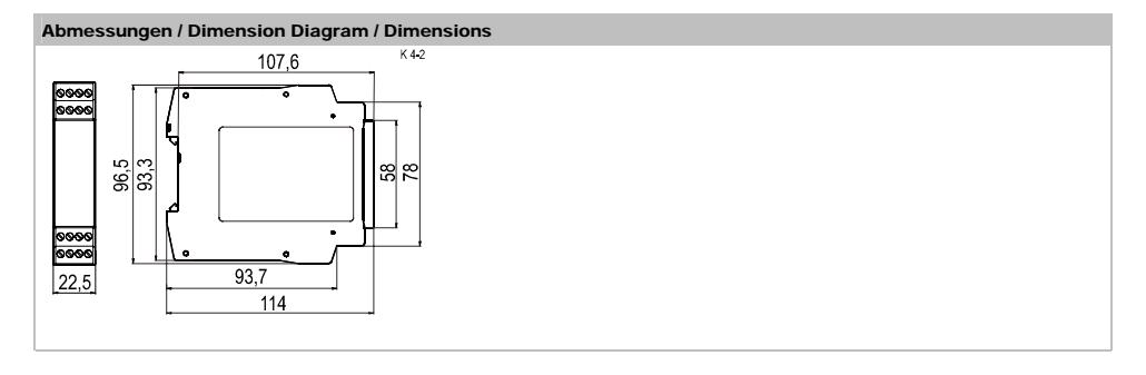
x
m m o m m x m m o m m . 8 |
|
|
rip
p g ng Fi nd ed ith ire nd fe st ne ra w w -e rru |
D
IN 4 62 28 to |
m
ax m m 1 0. 25 ² t 2. 5 ² 2 0. 25 ² t 0. 5 ² x m m o m m x m m o m m |
|
ly-
le M . t ig ht in to ax en ue |
0.
5 to 0 .6 N m |
|
|
g
rq Fo r U L d CS A lic io Co nd ize at to an ap p ns uc r s s ig ht in M . t to ax en g rq ue |
AW
G 18 -1 6 ly Cu li us e on ne s |
|
|
in
-lb 0. 79 s |
||
Änderungen vorbehalten / Subject to changes / Sous réserve de modification
GE Security Industrial 12345 SW Leveton Drive Tualatin, Oregon 97062 United States