Edwards Signaling INT-05 Series Installation Instructions 2013
Open the original PDF document
View PDF

www.edwardssignaling.com
Description
The INT-05-024 or INT-05-120 Expansion Safety Relay is intended for use as part of a safety circuit. It provides three additional safe output contacts when used with the INT-03 Safety Monitor Relay or INT-04 Emergency-Stop Safety Relay.
The INT-05 uses positive-guided relays along with feedback contacts to the INT-03 or INT-04 safety relay to prevent machine start-up in the event of a component failure.
Voltage to the INT-05 is switched thru the contacts of the INT-03 or INT-04. If a component failure occurs, the feedback loop to the INT-03 or INT-04 prevents machine restart.
TUV Notes:
- 1. Relay conforms to Pollution Degree II, meets EN1760-1:1998, and must be installed in an IP54-type enclosure.
- 2. The wire insulation of connected devices must be rated for 250VAC. The relay meets basic insulation requirements only.
- 3. Input devices must meet requirements of EN60947-5-1.
- 4. The relay must be connected to a primary disconnect device that meets the requirements of EN60947-3.
- 5. Controller meets IP20.
- 6. Test system before operation and after machine maintenance. Controller does not require maintenance.
- 7. The complete system should be tested weekly. If a fault occurs, contact Sentrol Industrial.
- 8. To be used in conjunction with INT-03 or INT-04.
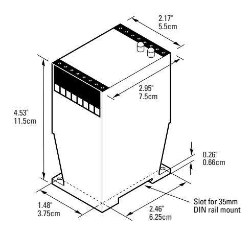
Dimensions
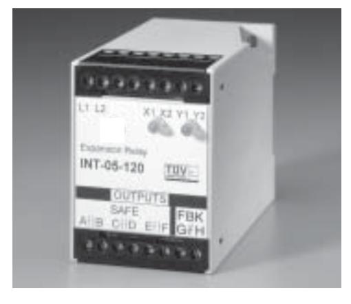
Integrity Series
Safety Expansion Relay
INT-05 INT-05-120
INT-05-024
INT-05 __________
Installation
- 1. Mount the relay on a 35mm DIN rail or panel. See Dimensions.
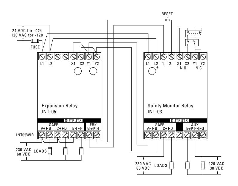
- 2. Connect the wiring for the switches and relay. See Wiring Diagrams. (For proper operation, DO NOT jumper terminal 1 to terminal 2. Use a momentary button.) For floor mat applications, connect the two floor mat loops from terminal X1 to X2 and from Y1 to Y2.
Caution! The relay is available in either a 24 VDC, 120 VAC, or 230 VAC model. Make sure correct model is used before applying power.
- 3. Use one of the following methods to energize the relay:
- • For E-stop installations, close all E-stop button contacts and monitored contacts, and then press the START button.
- • For floor mat installations, press the START button without an object on the mat.
Note: The INT-05 must be wired as shown as the unit on its own does not fulfill any safety requirements.
Typical Wiring Diagram


Declaration of Conformity available upon request.
European Directives
Machinery Directive (98/37/EEC) Low Voltage Directive (73/23/EEC), LVD
Specific European Standards
EN60204-1 Safety of electrical equipment of industrial machines: 1993
EN954-1 Risk Assessment Category 4 depending on wiring method, See diagrams: 1997
EN50081-2 Electromagnetic Emissions: 1995 EN50082-2 Electromagnetic Immunity: 1995
IEC 664-1 Insulation requirements: 1992 IEC 68, part 2-1, 2-2, 2-3, 2-6, 2-14, 2-27, 2-30.
EN1760-1:1998
General Specifications
| UL/CSA/TUV | CSA submitted | |
|---|---|---|
| Environmental Rating | Pollution Degree II | |
| Temperature Range | 32°F to 149°F (-0°C to 65°C) | |
| Relative Humidity | 30 to 95% non-condensing | |
| Control Inputs (X1, | X2 & Y1, Y2 terminals) | |
| Open-circuit voltage | 24VDC | |
| Closed-circuit current | 24mA | |
| Max. contact resistance | 30 Ohms | |
| Simultaneity | 500 ms typical | |
| Safe Outputs (A,B/ | C,D/E,F terminals) | |
| Voltage | 230 VAC/60VDC | |
| Current | 4A (resistive) each output | |
| Response time | ON: <40ms, OFF:<30ms | |
| Fuse | 4A, 250V, 5 x 20 mm | |
| AUX. Signaling Out | puts (F1,F2 terminals) | |
| Voltage | 120 VAC/30VDC | |
| Current | 1A (resistive) | |
Note: Transient protection is required across the load when switching an inductive load.

Ordering/Electrical Specifications
| PART NUMBER | POWER INPUT (L1, L2) | INPUT FUSE REQUIRED |
|---|---|---|
| INT-05-024 1 | 24VDC +/-15% | Fast acting 1/4A (250V, 5 x 20mm, F) |
| INT-05-120 2 | 120VAC +10% -20%, 5VA, 50/60Hz | Fast acting 80mA (250V, 5 x 20mm, F) |
1 Max of 80 expansion relays in series with INT-03 or INT-04.
& lt;sup>2</sup> Max of 1 expansion relay in series with INT-03 or INT-04.