Edwards Signaling I-107XBR LED Beacon Installation Instructions
Open the original PDF document
View PDF

107XBR Series Hazardous Location LED Strobe Light Installation Sheet
Description
The 107XBR Series Hazardous Location LED Strobe Lights are intended for general utility signaling use. They are available in pendant, bracket, or ceiling mount configurations and in 120 V 60 Hz and 24 VDC models. The 107XBR Series is factory-shipped in the steady mode, but upon activation of a third (yellow) wire to ground the strobe switches from the steady mode to a flashing mode that produces about 65 FPM.
These devices are UL and cUL Listed for use in Class I, Division 2, Group A, B, C, and D, and Class II, Division 2, Groups F and G, and Class III hazardous or nonhazardous locations. Pendant-mount versions with clear globes are also listed for Class II, Division 1, Group E, F, and G hazardous or nonhazardous locations. See Table 1 for operating temperature codes.
The devices are UL and cUL Listed as Type 3R and 4 enclosures and are marine rated.
Installation
Install this strobe in accordance with the applicable requirements in the latest edition of the NFPA 70 National Electrical Code or CSA C22.1 Canadian Electrical Code , using supply wire rated as shown in Table 1.
WARNINGS
- Explosion hazard. To reduce the risk of ignition of hazardous atmospheres and shock, keep the assembly tightly closed when circuits are energized.
- Explosion hazard. Substitution of any component may impair suitability for Class I, Division 2.
Three mounting options are available for the 107XBR Series:
- Pendant mount
- Bracket mount
- Ceiling mount
Select the appropriate method from the three options given below. Critical dimensions for each option are shown in the following figures.
Figure 1: Pendant mount
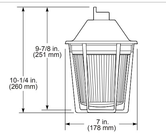
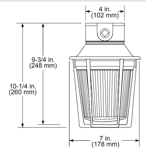
Figure 2: Bracket mount
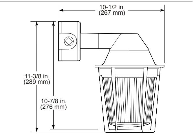
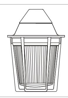
Figure 3: Ceiling mount
To install pendant mount models:
- 1. Install an explosion-proof hanger box (not supplied). Pull the strobe wire leads through the 3/4 in. NPT threaded conduit (not supplied).
- 2. Secure the 3/4 in. threaded conduit to the mounting hood.
- 3. Ground the strobe in accordance with NFPA 70 or CSA C22.1 and local requirements.
- 4. Wire in accordance with the instructions in "Wiring" on page 2.
- 5. Secure the 3/4 in. threaded conduit to the outlet box.
- 6. Where applicable, install the optional guard assembly over the clear outer globe and secure it using the three screws supplied.
- 7. Apply power to the strobe and ensure proper function.
To install bracket mount models:
- 1. Remove the outlet box from the end of the mounting bracket. Install the outlet box using appropriate hardware (not supplied) for the mounting surface. Pull the field wiring through the outlet box.
- 2. Ground the strobe in accordance with NFPA 70 or CSA C22.1 and local requirements.
- 3. Wire in accordance with the instructions in "Wiring" below.
- 4. Mount the wall bracket onto the outlet box.
- 5. Where applicable, install the optional guard assembly over the clear outer globe and secure it using the three screws supplied.
- 6. Apply power to the strobe and ensure proper function.
To install ceiling mount models:
- 1. Unscrew and remove the clear outer globe. Remove the two screws holding the circuit assembly to the bottom of the fixture. To separate the ceiling junction box from the fixture housing, remove the remaining two screws at the bottom of the fixture.
- 2. Mount the ceiling junction box using appropriate hardware. Pull the field wiring through the ceiling junction box.
- 3. Wire in accordance with the instructions in "Wiring" below.
- 4. Secure the fixture housing on the junction box by replacing the two screws removed above. Reinstall the circuit assembly to the bottom of the fixture using the two screws removed earlier.
- 5. Screw the clear outer globe back on to the fixture housing.
- 6. Where applicable, install the optional guard assembly over the clear outer globe and secure using three screws (supplied).
- 7. Apply power to the strobe and ensure proper function.
Wiring
To wire 24 VDC models:
- 1. Connect the red wire lead to the positive terminal of the power source. See Figure 4.
- 2. Connect the black wire to the negative terminal or ground of the power source.
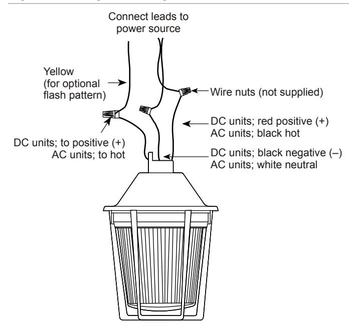
- 3. If desired, set the flash pattern to 65 FPM by connecting the yellow wire to the positive terminal. See Figure 5.
To wire 120 VAC models:
- 1. Connect the black wire to the AC hot terminal. See Figure 4.
- 2. Connect the white wire to the AC neutral terminal.
- 3. If desired, set the flash pattern to 65 FPM by connecting the yellow wire to the hot terminal. See Figure 5.
Figure 4: Steady mode wiring
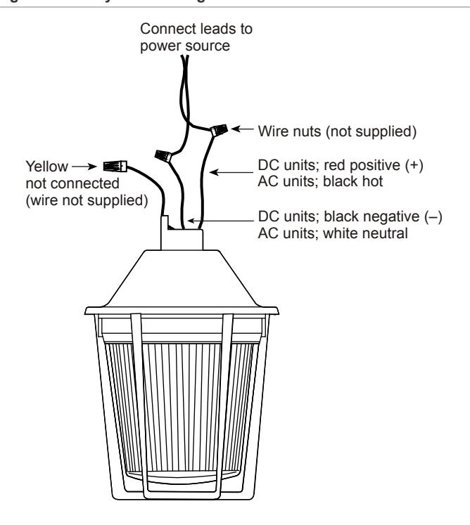
Figure 5: Flashing mode wiring
Maintenance
The strobe's exterior surfaces and the outer globe should be cleaned periodically with a soft, clean cloth using water and a mild detergent to maintain optimum light visibility. Disconnect the power before cleaning.
It is not necessary to disassemble the strobe to accomplish periodic cleaning.
WARNINGS
- Shock hazard. To prevent electrical shock, disconnect the power before removing the outer globe.
- Shock hazard. To avoid risk of injury, install the outer globe before energizing the strobe.
Specifications
Table 1: Operating temperatures
| Ambient |
Supply
wire |
Class I, Div. 2,
Groups A, B, C, D |
Class II, Div. 1, Groups E,
F, G; Class II, Div. 2, Groups F, G; Class III, Div. 1 and 2 |
|---|---|---|---|
| 40°C | 60˚C | 135°C (T4) | 85°C (T6) |
| 55°C | 75˚C | 135°C (T4) | 85°C (T6) |
| 65°C | 105˚C | 135°C (T4) | 85°C (T6) |
Note: Class II and Class III apply only to the pendant mount versions with clear globes.
Table 2: Electrical specifications
| 120 VAC | 24 VDC |
|---|---|
|
107XBRPM*120A
107XBRBM*120A 107XBRCM*120A |
107XBRPM*24D
107XBRBM*24D 107XBRCM*24D |
| 0.215 A | 0.105 A |
| See Table 1 | |
| 3/4 in. NPT | |
| 65 FPM** | |
* Letter denotes the color of the inner lens: A = Amber, B = Blue, G = Green, R = Red, or W = White
Regulatory information
|
North American
standards |
ANSI/ISA 12.12.01
CSA C22.2 No. 25 CSA C22.2 No. 30, CSA C22.2 No. 213 UL 50, UL 1203, UL 1638, |
| UL and cUL ratings |
Class I, Division 2, Groups A, B, C and D
Class II, Division 1, Groups E, F, G* Class II, Division 2, Groups F, G* Class III, Divisions 1 and 2* Type 3R, 4, Marine** |
* Class II and Class III only apply to the pendant mount versions with clear globes.
Contact information
For contact information, see www.edwardssignaling.com.
© 2014 UTC Fire & Security Americas Corporation, Inc. All rights reserved.
** Only when the flashing mode is activated by connecting the third (yellow) wire. See "Wiring" on page 2.
** Marine rating applies to the UL Listing only.