Edwards Signaling HSL Series Installation Instructions
Open the original PDF document
View PDF

Installation Instructions for the HSL Series Homeland Security Light

Description
The Edwards Homeland Security Light is a unique audible-visual signaling device that contains either five LED light modules or five incandescent light modules and a multiple tone module in a single "stack."
All components of the Triliptical Stackable Beacon Lighting System are UL listed subassemblies. The units are UL listed for indoor and outdoor applications and CSA certified. The enclosures are NEMA 3R, 4X, and IP65
rated. CE Marked Visual Signal.
The stacklight comes assembled with five color modules as used by the Homeland Security Advisory System: green, blue, yellow, orange, and red. See Table 1. Each lens module contains a removable cover to allow for easy relamping. The lens module cover features a molded-in gasket for weather tight reliability.
The unit features a large base with a terminal block with a multiple tone module installed. The larger base also functions as a junction box.
A pipe mount kit, Cat. No. 102PMF (sold separately) and one of three extension pipes (sold separately) allows the status indicator to be raised above the mounting surface for increased visibility.
PLC Compatibility
The electrical input characteristics for PLC compatible signals are listed in Table 2. Signals with these characteristics may be directly connected to PLC output cards that do not exceed these input characteristics.
Installation
Installation must be in accordance with the latest edition of the National Electrical Code and other governing standards and codes for standard installation.
1. If using the 102PMF mounting kit, perform the following:

WARNINGS
To prevent electrical shock, do not connect power until instructed to do so.
To prevent abrasion of wiring insulation, ensure that wire passage holes are adequately protected.
NOTE: All references below are to Figure 4.
- a. Using the supplied gasket (D) as a guide, mark the four mounting holes and the center clearance hole on an appropriate surface.
- b. Punch the four mounting holes. Punch the wiring clearance hole in the mounting surface to be sufficiently larger than that in the gasket to ensure the wiring insulation is protected from abrasion by the gasket (without interfering with the mounting screw holes), or provide other appropriate wire insulation abrasion protection as needed.
- Screw the pipe extension (purchased separately) into the mounting flange.
- d. Ground the flange by pulling the ground wire through the mounting surface clearance hole and center hole of the gasket. Connect earth ground to the bottom of the base mount flange using the ground screw (G) and wire retention terminal cup washer (H).
- e. Pull the remaining field wiring through center clearance hole of mounting surface, center hole of the gasket, pipe mount flange and extension pipe.
- f. Align the mounting gasket (D) and flange (A) on the panel. Secure using (4) #10-24 x 1" (25 mm) pan head screws (B), (4) external tooth #10 star washers (E) and (4) #10-24 hex nuts (F).
- g. Mount the base as instructed below.
NOTE: For NEMA3R, 4X, and outdoor applications, it is recommended that the unit be conduit mounted vertically facing up.
- 2. Install base on 3/4" (19 mm) conduit (not supplied). Pull field wiring through conduit entrance hole.
- 3. Connect field wiring to the terminal blocks as shown in Figures 1 and 2.
NOTE: The tone module may be wired to sound independently or in conjunction with a light signal.
- To sound tone module independently, connect to separate hot lead.
- To sound tone module with a particular light, connect horn hot terminal to selected light terminal on Cat. No. 102TBS terminal block.
- 4. Apply power to the unit and verify proper operation.
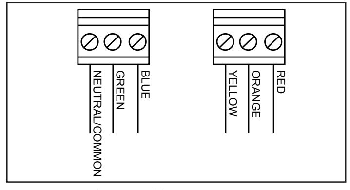
Figure 1. Wiring Cat. No. 102TBS
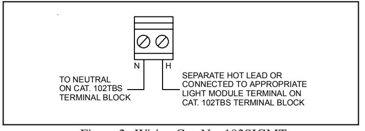
Figure 2. Wiring Cat. No. 102SIGMT
Maintenance
Light Source Replacement
- Loosen captive screws and remove cover of affected lens module.
- 2. Remove the light source assembly from the lens module.
- Install new light source assembly ensuring that the four prongs on the PC board are aligned with the plug located in the back of the lens module.

WARNING
To prevent leakage, ensure the magnifier ring on the lens cover and the magnifier ring on the lens module are aligned (Figure 3).
4. Replace lens cover and secure using two captive screws.
Cleaning
The lens surfaces should be periodically dusted and cleaned with a dry soft clean cloth to maintain optimum light visibility. If necessary, the outside of the lens may be cleaned with water and a mild detergent on a well rung-out, soft, clean cloth.
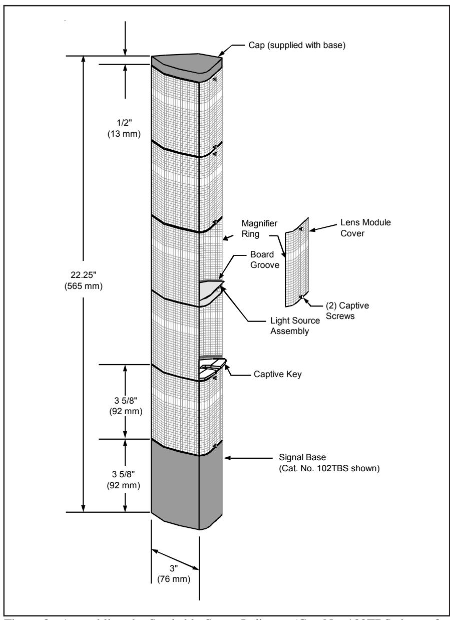
Figure 3. Assembling the Stackable Status Indicator (Cat. No. 102TBS shown for illustration purposes only)
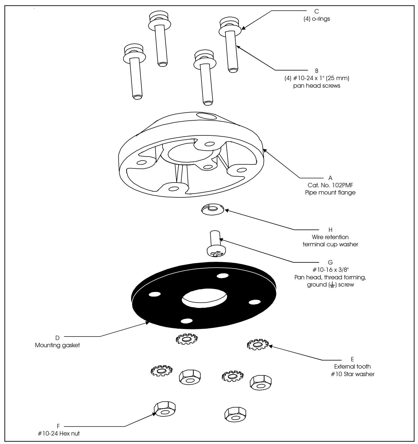
Figure 4. Optional 102PMF Mounting Kit Assembly
Table 1. Specifications
| Catalog No. |
Electrical
Ratings |
Manufacturers
Lamp Ratings |
Replacement
Lamp |
Lamp Life (hours) | |
|---|---|---|---|---|---|
| Calculated# | Projected## | ||||
| Base Units | |||||
| 102TBS-G1 | 24V DC, 1.75A+ | N/A | N/A | N/A | N/A |
| 102TBS-N5 | 120V AC, 0.60A+ | ||||
| Optional Pipe Mount Flange | |||||
| 102PMF | N/A | N/A | N/A | N/A | N/A |
| Optional Extension Pipes | |||||
| 102MP-4 | N/A | N/A | N/A | N/A | N/A |
| 102MP-10 | N/A | N/A | N/A | N/A | N/A |
| 102MP-15 | N/A | N/A | N/A | N/A | N/A |
| Horn Assembly | |||||
| 102SIGMT-G1 | 24V DC, 0.05A | N/A | N/A | N/A | N/A |
| 102SIGMT-N5 | 120V AC, 0.07A | ||||
| Lens Modules | |||||
| 102LM-* | N/A | N/A | N/A | N/A | N/A |
| Light Sources | |||||
| 102LS-SIN-G1 | 24V DC, 0.32A | 10 Watts | Ind. Trade 303 | 10,000 | |
| 102LS-SIN-N5 | 120V AC, 0.08A | 10 Watts | 50LMP-10W | 2,500 | |
| 102LS-SLEDA-G1** | 24V DC, 0.062A | N/A | 100,000 | ||
| 102LS-SLEDB-G1** | |||||
| 102LS-SLEDG-G1** | |||||
| 102LS-SLEDR-G1** | |||||
| 102LS-SLEDW-G1** | |||||
| 102LS-SLEDA-N5** | 120V AC, 0.022A | N/A | 100,000 | ||
| 102LS-SLEDB-N5** | |||||
| 102LS-SLEDG-N5** | |||||
| 102LS-SLEDR-N5** | |||||
| 102LS-SLEDW-N5** | |||||
+ Currents shown are for a stackable indicator with 5 light modules.
Table 2. PLC Compatibility
| Cat. No. |
Unit input
voltage* |
Maximum leakage
current (mA) |
Continuous on
current (mA) |
Peak current
inrush/duration (A/ms**) |
|---|---|---|---|---|
| 102SIGMT-G1 | 24V DC | 5 | 50 | 0.24/0.2 |
| 102SIGMT-N5 | 120V AC | 5 | 70 | 0.35/0.5 |
| 102LS-SIN-G1 | 24V DC | 25 | 32 | 0.36/1 |
| 102LS-SIN-N5 | 120V AC | 25 | 80 | 0.15/8 |
| 102LS-SLED( )-G1 | 24V DC | 5 | 65 | 0.07/1 |
| 102LS-SLED( )-N5 | 120V AC | 5 | 25 | 0.09/8 |
* All AC volts at 60 Hz
* Signifies lens module color (A - amber/orange, B - blue, C - clear, G - green, R - red, Y - yellow)
** Signifies lens and LED module color (A - amber/orange, B - blue, G - green, R - red) NOTE: LED light sources must be used with the corresponding color lens module (e.g., a blue LED light source, 102LS-SLEDB-G1, must be used with a blue lens, 102LM-B). For yellow modules, use the 102LS-SLEDW light source.
# At nominal operating voltage.
## Projected lamp life based on manufacturer's calculated lamp life @ 65 fpm and 50% duty cycle.
** Amps/milliseconds