Edwards Signaling Genesis Temporal Horn Strobe Installation Sheet
Open the original PDF document
View PDF

Genesis Temporal Horn-Strobe Installation Sheet
Description
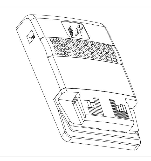
The Genesis Temporal Horn-Strobe is a fire alarm notification appliance designed for indoor walls. See Table 1 for a list of model numbers.
Table 1: Models
| Description | Number | |
|---|---|---|
| Horn-strobe, | ADTG1-HDVM | MG1-HDVM |
| 15 to 110 multi-cd, | EG1-HDVM | XLSG1-HDVM |
| white | G1-HDVM | ZG1-HDVM |
| Horn-strobe, | ADTG1F-HDVM | MG1F-HDVM |
| 15 to 110 multi-cd, | EG1F-HDVM | XLSG1F-HDVM |
| white, with FIRE marking | G1F-HDVM | ZG1F-HDVM |
| Horn-strobe, | ADTG1R-HDVM | MG1R-HDVM |
| 15 to 110 multi-cd, | EG1R-HDVM | XLSG1R-HDVM |
| red | G1R-HDVM | ZG1R-HDVM |
| Horn-strobe, | ADTG1RF-HDVM | MG1RF-HDVM |
| 15 to 110 multi-cd, | EG1RF-HDVM | XLSG1RF-HDVM |
| red, with FIRE marking | G1RF-HDVM | ZG1RF-HDVM |
|
Trim plate,
white |
ADTG1T
EG1T G1T |
MG1T
XLSG1T ZG1T |
|
Trim plate,
white, with FIRE marking |
ADTG1T-FIRE
EG1T-FIRE G1T-FIRE |
MG1T-FIRE
XLSG1T-FIRE ZG1T-FIRE |
| Description | Number | |
|---|---|---|
|
Trim plate,
red |
ADTG1RT
EG1RG 1RT |
MG1RT
XLSG1RT ZG1RT |
|
Trim plate,
red, with FIRE marking |
ADTG1RT-FIRE
EG1RT-FIRE G1RT-FIRE |
MG1RT-FIRE
XLSG1RT-FIRE ZG1RT-FIRE |
There are field-configurable options for selecting dB output, horn signal, or strobe signal output. See Figure 1.
The strobe includes a field-configurable switch for selecting the desired candela output. The candela output setting is locked in place and remains visible after final installation. See Figure 2.
This strobe features an enhanced synchronization circuit to comply with the latest requirements of UL 1971 Signaling Devices for the Hearing Impaired and the latest Canadian standard CAN/ULC-S526. Synchronized operation requires a separately installed synchronization control module. See Table 2 for a list of compatible synchronization modules.
Table 2: Compatible synchronization module models [1]
| Description | Number | ||
|---|---|---|---|
|
Genesis Signal Master
Snap-on Mount |
EG1M
ADTG1M |
MG1M
XLSG1M |
G1M
ZG1M |
|
Genesis Signal Master -
Remote Mount |
EG1M-RM | MG1M-RM | G1M-RM |
| Auto-Sync Output Module | SIGA-CC1S SIGA-MCC1S | ||
| Dual Input Signal Module | SIGA-CC2A SIGA-MCC2 A | ||
| Auxiliary Power Supply | APS6A | APS10A | |
| Power Supply | BPS6A | BPS10A | |
[1] Synchronization module requirements are determined by the application.
Installation
Install this device in accordance with applicable requirements in the latest editions of the NFPA codes and standards; the National Building Code of Canada; the Canadian Electrical Code, Part 1, Section 32, and in accordance with the local authorities having jurisdiction.
WARNING: Electrocution hazard. To avoid personal injury or death from electrocution, remove all sources of power and allow stored energy to discharge before installing or removing equipment.
Caution: Electrical supervision requires breaking the wire run at each terminal. Do not loop the signaling circuit field wires around the terminals.
To install the horn-strobe:
- 1. Remove the cover by depressing both tabs on the top of the unit with a small screwdriver and twisting slightly.
-
2. Set the horn signal, sound output level, and strobe signal to the desired settings. See Figure 1.
- To change the strobe to temporal (private mode), cut from circle J1 to the edge of circuit board.
- To change the horn signal from temporal to steady, cut from circle J2 to the edge of circuit board.
- To change the horn output level from high dB to low dB, cut the J3 trace between the holes.
- 3. Slide the candela switch to the desired candela output by aligning it with the indicator located left of the switch. See Figure 2.
- 4. Connect the strobe terminals to the signal circuit field wiring. You must observe polarity for the unit to function properly. See Figure 3.
- 5. Mount the unit onto a compatible electrical box, making sure not to overtighten the mounting screws.
- 6. Replace the cover by aligning it at the bottom, then snapping it in at the top.
- 7. Test the unit for proper operation.
Figure 1: Horn and strobe settings
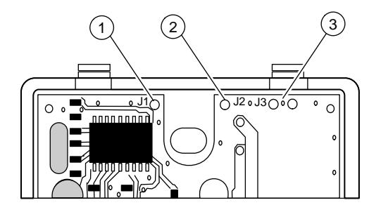
- 1. J1: Strobe signal output
- 2. J2: Temporal/steady horn signal output
- 3. J3: dB sound output
Note: If the strobe is set to temporal (private mode), this device is no longer UL 1971 listed and FM Approved but is UL 1638 listed.
Figure 2: Candela switch
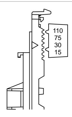
Figure 3: Wiring diagram
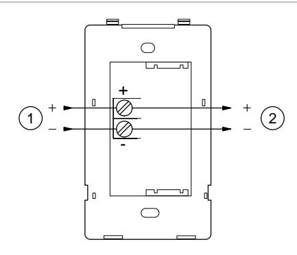
- 1. From compatible fire alarm control panel
- 2. To next appliance, EOL, or return to source
Note: Polarity is shown in the alarm condition.
Maintenance
Caution: To maintain the required agency listings, do not change factory applied finishes.
This unit is not serviceable or repairable. Should the unit fail to operate, contact the supplier for replacement.
Perform a visual inspection and an operational test twice a year or as directed by the local authority having jurisdiction.
Specifications
| 24 VDC or 24 VFWR nominal |
| See Table 7 |
| See Table 3 and Table 4 |
| See Table 5 and Table 6 |
| Selectable at 15, 30, 75, and 110 cd |
|
Maximum allowed resistance between any
two devices is 20 Ω. Refer to specifications for the synchronization control module, this strobe, and the control panel to determine allowed wire resistance. |
| 1 flash per second (fps) |
| 12 to 18 AWG (0.75 to 2.50 mm²) |
|
2-1/2 in. (64 mm) deep single-gang box
4 in. square box 1-1/2 in. (38 mm), 2-gang 4 in. octagonal with G1T or G1RT trim accessory |
|
32 to 120°F (0 to 49°C)
0 to 93% noncondensing |
Table 3: UL Ratings, temporal output
| Signal and voltage | Low | High |
|---|---|---|
| Temporal | 76.0 | 81.4 |
| Continuous | 80.1 | 85.5 |
UL 464: Sound level output at 10 ft. (3.05 m) measured in a reverberant room at 16 V.
Table 4: Sound level output (dBA, temporal tone)
| Voltage | High | Low | |
|---|---|---|---|
| 16 VDC | 97.6 | 93.8 | |
| 24 VDC | 101.4 | 97.3 | |
| 33 VDC | 103.8 | 99.7 | |
| 16 VFWR | 101.3 | 97.3 | |
| 24 VFWR | 104.2 | 100.4 | |
| 33 VFWR | 106.0 | 102.7 |
CAN/ULC-S525: Meets or exceeds 85 dBA in an anechoic chamber at 10 ft. (3.05 m)
Table 5: Audible directional characteristics (horizontal pattern)
| Angle (°) [1] | Output (dB) [2] |
|---|---|
| 0 | 0 |
| +18 | −3 |
| +42 | −6 |
| -50 | −3 |
| -75 | −6 |
[1] Angles are measured from a perpendicular axis; positive angles to the right.
[2] Peak output at 16 VDC, set for steady tone
Table 6: Audible directional characteristics (vertical pattern)
| Angle (°) [1] | Output (dB) [2] |
|---|---|
| 0 | 0 |
| +20 | −3 |
| +45 | −6 |
| −20 | −3 |
| −52 | −6 |
[1] Angles are measured from a perpendicular axis; positive angles are up.
[2] Peak output at 16 VDC, set for steady tone.
Table 7: Operating horn-strobe current in RMS (A)
| Voltage | Strobe (cd) | Operating current |
|---|---|---|
| VDC | 15 | 0.129 |
| 30 | 0.167 | |
| 75 | 0.281 | |
| 110 | 0.337 | |
|
VFWR
15 30 75 110 |
0.176 | |
| 0.230 | ||
| 0.397 | ||
| 0.443 |
VDC = Volts direct current, regulated and filtered VFWR = Volts full wave rectified
Operating currents shown above were measured by UL at 16 VDC and 16 VFWR and high dB setting.
Figure 4: UL 1971 minimum light output (% of rating vs. angle)
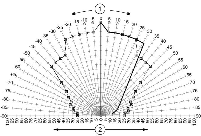
1. Angle
2. Minimum UL required candela light output ____ % of rated candela vertical specification
- - - - % of rated candela horizontal specification
Figure 5: Typical horizontal light output profile, 110 cd setting
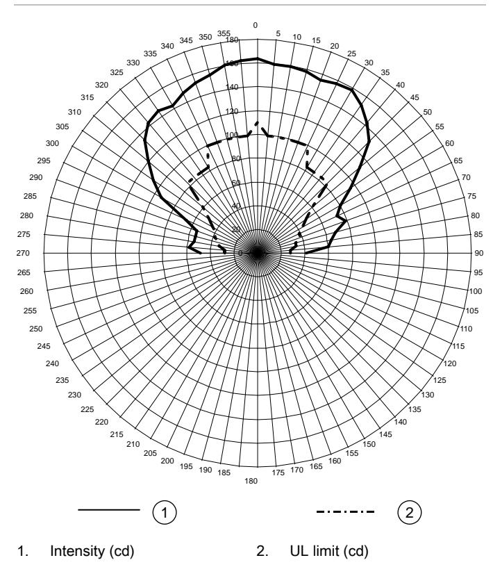
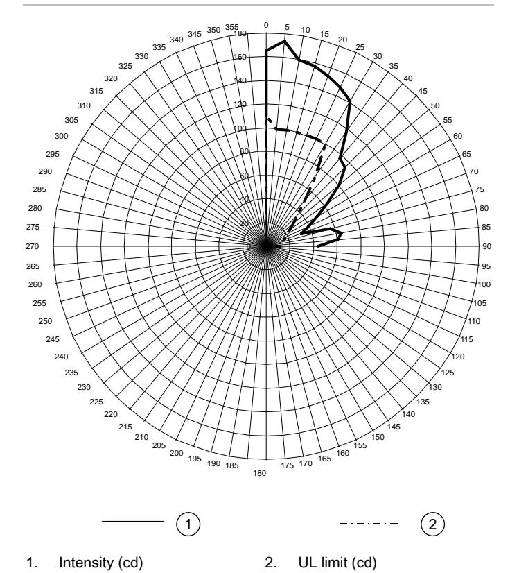
Figure 6: Typical vertical light output profile, 110 cd setting
Regulatory information
| Manufacturer |
Edwards, A Division of UTC Fire & Security
Americas Corporation, Inc. 8985 Town Center Parkway, Bradenton, FL 34202, USA |
|
Year of
manufacture |
The first two digits of the date code (located on
the product identification label) are the year of manufacture. |
| UL rating | Regulated 24 DC and 24 FWR |
|
North American
standards |
Meets UL requirements for standards UL 464,
UL 1638 and UL 1971 (see Figure 1) and Canadian requirements for standards ULC-S525 and ULC-S526. |
Contact information
For contact information, see www.utcfireandsecurity.com.