Edwards Signaling Genesis Temporal Horn Installation Sheet
Open the original PDF document
View PDF

Genesis Temporal Horn Installation Sheet
Description
The Genesis Temporal Horn is an audible fire alarm notification appliance designed for indoor walls. See Table 1 for a list of model numbers.
The horn includes field configurable jumper options for selecting:
- Temporal or steady horn output (see Figure 1 item 1)
- High dB or low dB output (see Figure 1 item 2)
Table 1: Models
| Description | Number | |
|---|---|---|
|
Temporal horn,
white |
ADTG1-HD
EG1-HD G1-HD G1-HD-LG |
MG1-HD
XLSG1-HD ZG1-HD |
|
Temporal horn,
white, with FIRE marking |
ADTG1F-HD
EG1F-HD G1F-HD G1F-HD-LG |
MG1F-HD
XLSG1F-HD ZG1F-HD |
|
Temporal horn,
red |
ADTG1R-HD
EG1R-HD G1R-HD G1R-HD-LG |
MG1R-HD
XLSG1R-HD ZG1R-HD |
|
Temporal horn,
red, with FIRE marking |
ADTG1RF-HD
EG1RF-HD G1RF-HD G1RF-HD-LG |
MG1RF-HD
XLSG1RF-HD ZG1RF-HD |
|
Trim plate,
white |
ADTG1T
EG1T G1T G1T-LG |
MG1T
XLSG1T ZG1T |
|
Trim plate,
white, with FIRE marking |
ADTG1T
EG1T G1T G1T-LG |
MG1T
XLSG1T ZG1T |
|
Trim plate,
red |
ADTG1RT
EG1RT G1RT G1RT-LG |
MG1RT
XLSG1RT ZG1RT |
|
Trim plate,
red, with FIRE marking |
ADTG1RT
EG1RT G1RT G1RT-LG |
MG1RT
XLSG1RT ZG1RT |
Installation
Install this device in accordance with applicable requirements in the latest editions of the NFPA codes and standards; the National Building Code of Canad a; the Canadian Electrical Code, Part 1 , Section 32, and in accordance with the local authorities having jurisdiction.
Caution: Electrical supervision requires breaking the wire run at each terminal. Do not loop the signaling circuit field wires around the terminals.
To install the horn:
- 1. Remove the cover by depressing both tabs on the top of the unit with a small screwdriver and twisting slightly.
- 2. Set the horn signal and sound output level to desired settings. See Figure 1.
- 3. Connect the horn terminals to the signal circuit field wiring. Observe polarity for the unit to function properly. See Figure 1.
- 4. Mount the unit onto a compatible electrical box, making sure not to overtighten the mounting screws.
- 5. Replace the cover by aligning at the bottom, then snapping in at the top.
- 6. Test the unit for proper operation.
Figure 1: Horn settings
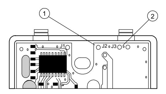
- 1. To change the horn signal from temporal to steady, cut from circle J2 to edge of circuit board
- 2. To change the horn sound output level from high dB to low dB. cut J3 by snipping the board trace between holes
Figure 2: Wiring diagram
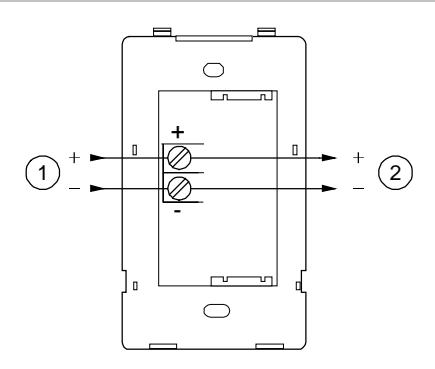
1. From NAC output
2. To next NAC output
Note: Polarity is shown in the alarm condition.
Maintenance
Caution: To maintain the required agency listings, do not change factory applied finishes.
This unit is not serviceable or repairable. Should the unit fail to operate, contact the supplier for replacement.
Perform a visual inspection and an operational test twice a year or as directed by the local authority having jurisdiction.
Table 2: Sound level output (dBA)
| Signal and voltage | Low | High | ||
|---|---|---|---|---|
| Temporal | 16 VDC | 76.0 | 81.4 | |
| 24 VDC | 79.4 | 84.4 | ||
| 33 VDC | 82.1 | 86.3 | ||
| Continuous | 16 VDC | 80.1 | 85.5 | |
| 24 VDC | 83.5 | 88.6 | ||
| 33 VDC | 86.5 | 90.4 | ||
UL 464: Sound level output at 10 ft. (3.05 m) measured in a reverberant room.
Table 3: Sound level output (dBA, temporal tone, peak)
| Tonal and voltage | High |
|---|---|
| 16 VDC | 98.8 |
| 24 VDC | 102.7 |
| 33 VDC | 104.3 |
| 16 VFWR | 102.4 |
| 24 VFWR | 105.0 |
| 33 VFWR | 106.9 |
CAN/ULC-S525: Meets or exceeds 85 dBA in an anechoic chamber at 10 ft. (3.05 m)
Table 4: Operating current in RMS (A)
| Voltage | High | Low |
|---|---|---|
| 16 VDC | 0.026 | 0.019 |
| 24 VDC | 0.036 | 0.027 |
| 33 VDC | 0.041 | 0.033 |
| 16 VFWR | 0.051 | 0.037 |
| 24 VFWR | 0.069 | 0.052 |
| 33 VFWR | 0.076 | 0.070 |
VDC = Volts direct current, regulated and filtered
VFWR = Volts full wave rectified
Table 5: Audible directional characteristics (horizontal pattern)
| Angle (°) [1] | Sound output (dBA) [2] | |
|---|---|---|
| −90 | 94 | |
| −45 | 97 (−6) | |
| −30 | 100 (−3 ) | |
| 90 | 103 | |
| 30 | 100 (3 ) | |
| 45 | 97 (6 ) | |
| 90 | 96 |
[1] Angles are measured from a perpendicular axis; positive angles to the right
[2] Peak output at 24 VDC, set for temporal tone.
Table 6: Audible directional characteristics (vertical pattern)
| Angle (°) [1] | Sound output (dBA) [2] |
|---|---|
| −90 | 94 |
| −40 | 97 (−6) |
| −25 | 100 (−3) |
| 90 | 103 dBA |
| 35 | 100 (3) |
| 45 | 97 (6) |
| 90 | 96 |
[1] Angles are measured from a perpendicular axis; positive angles are up.
[2] Peak output at 24 VDC, set for temporal tone.
Specifications
| Operating Voltage | Regulated 16 to 33 VDC, 16 to 33 VFWR |
| Current | |
| Alarm | 40 mA at 24 VDC |
| Operating | See Table 4 |
| Sound level output | See Table 2 and Table 3 |
|
Audible directional
characteristics |
See Table 5 and Table 6 |
| Wire size | 12 to 18 AWG (0.75 to 2.50 mm²) |
|
Compatible electrical
boxes |
North American 2-1/2 in. (64 mm) deep
single-gang box Standard 4 in. square box 1-1/2 in. (38 mm) deep box European 100 mm² box |
| Operating environment | |
| Temperature | 32 to 120°F (0 to 49°C) |
| Relative humidity | 0 to 93% noncondensing |
Note: This device was tested to the regulated 24 DC/FWR operating voltage limits of 16 V and 33 V. Do not apply 80% and 110% of these values for system operation.
Certification and compliance
| Manufacturer |
Edwards, A Division of UTC Fire & Security
Americas Corporation, Inc. 8985 Town Center Parkway, Bradenton, FL 34202, USA |
|
Year of
manufacture |
The first two digits of the date code (located on
the product identification label) are the year of manufacture. |
| UL rating | Regulated 24 DC and 24 FWR |
|
North American
standards |
CAN/ULC-S525 and UL 464 |
|
European Union
directives |
1999/5/EC (R&TTE directive): Hereby, UTC Fire
& Security declares that this device is in compliance with the essential requirements and other relevant provisions of Directive 1999/5/EC. |
|
2002/96/EC (WEEE directive): Products marked
with this symbol cannot be disposed of as unsorted municipal waste in the European Union. For proper recycling, return this product to your local supplier upon the purchase of equivalent new equipment, or dispose of it at designated collection points. For more information see: www.recyclethis.info. |
|
|
2004/108/EC (EMC directive): Non-European
manufacturers must designate an authorized representative in the Community. Our authorized manufacturing representative is: |
|
|
UTC Fire & Security B.V.
Kelvinstraat 7, 6003 DH Weert, Netherlands |
Contact information
For contact information, see www.edwardsutcfs.com.