Edwards Signaling Genesis Low Frequency (520 Hz) Horn Installation Sheet
Open the original PDF document
View PDF

Genesis Low Frequency (520 Hz) Horn Installation Sheet
Description
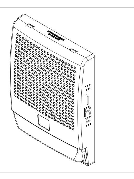
The Genesis Low Frequency (520 Hz) horn can be used for applications where a low frequency alarm notification appliance is required. The device is designed for indoor use only and can be mounted on the wall or ceiling. See Table 1 for a list of model numbers.
The horn includes field-configurable jumper options for selecting:
- Temporal or steady horn output
- High dB or low dB output
Table 1: Models
| Description | Number |
|---|---|
|
Low frequency (520 Hz) horn, white housing,
no FIRE marking |
G4LFWN-H |
|
Low frequency (520 Hz) horn, white housing,
with FIRE marking |
G4LFWF-H |
|
Low frequency (520 Hz) horn, red housing, no
FIRE marking |
G4LFRN-H |
|
Low frequency (520 Hz) horn, red housing,
with FIRE marking |
G4LFRF-H |
| Surface mount box, white housing | G4B |
| Surface mount box, red housing | G4RB |
Installation
Install and wire this device in accordance with applicable national and local codes, ordinances, and regulations.
Note: Electrical supervision requires that you break the wire run at each terminal. Do not loop wires around the terminals.
To install the horn:
- 1. Remove the cover by using a screwdriver to depress and slightly twist both tabs on top of the unit.
- 2. Set the horn signal and sound output level to desired settings. See Figure 1.
To change the horn output level from high dB to low dB, cut jumper JP3.
To change the horn signal from temporal to steady, cut jumper JP2.
3. Mount the horn as follows.
Note: Route the signal circuit field wiring through the cutout in the center of the horn.
Flush mount: Mount the horn and flush mount spacer onto a compatible electrical box (Figure 2), making sure not to overtighten the mounting screws. See "Specifications" for compatible electrical boxes.
Surface mount: Mount the G4B or G4RB surface mount box on the wall or ceiling (Figure 3), and then secure the appliance to the box using the screws provided with the box.
- 4. Connect the signal circuit field wiring to the horn terminals (Figure 4). Observe polarity for the unit to function properly.
- 5. Replace the cover by aligning it at the bottom, and then snapping it in at the top (Figure 2 and Figure 3).
- 6. Test the unit for proper operation.
Figure 1: Horn settings
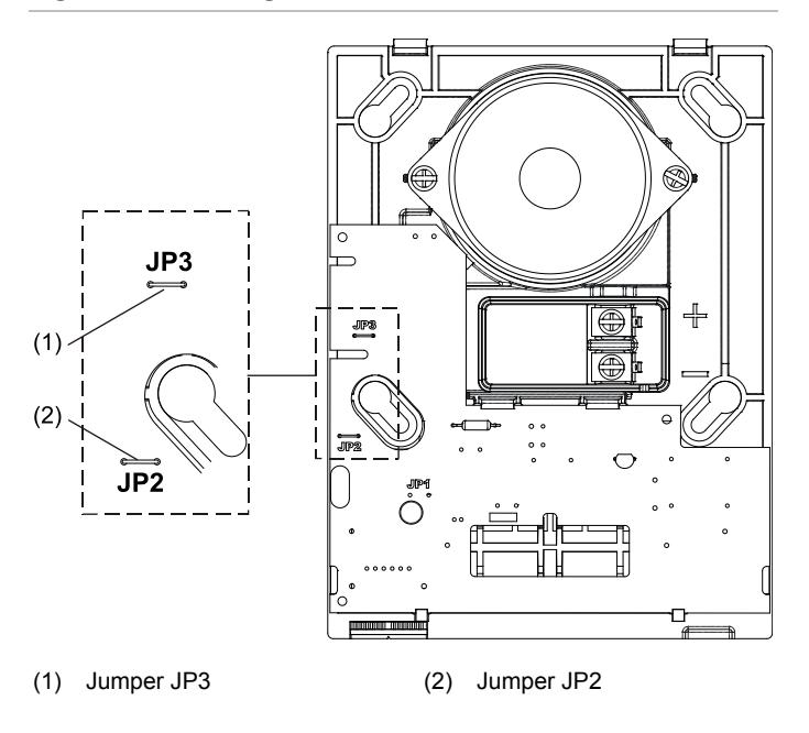
Figure 2: Flush mount
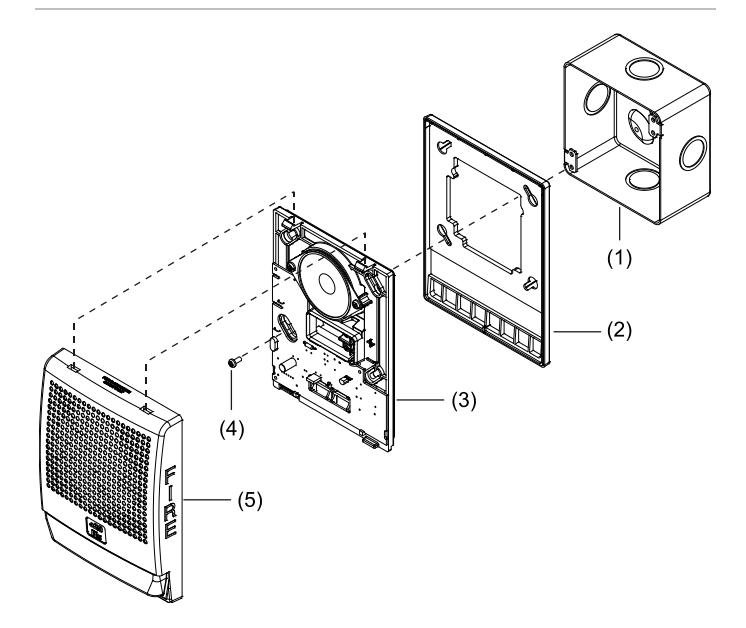
- (1) Compatible electrical box
- (2) Flush mount spacer
- (3) Horn
- (4) 8-32 x 1 in. screw 2X (provided)
- (5) Cover
Figure 3: Surface mount
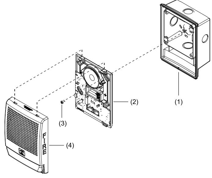
- (1) Surface mount box (G4B or G4RB)
- (2) Horn
- (3) Screw 4X (provided with G4B or G4RB box)
- (4) Cover
Figure 4: Wiring diagram
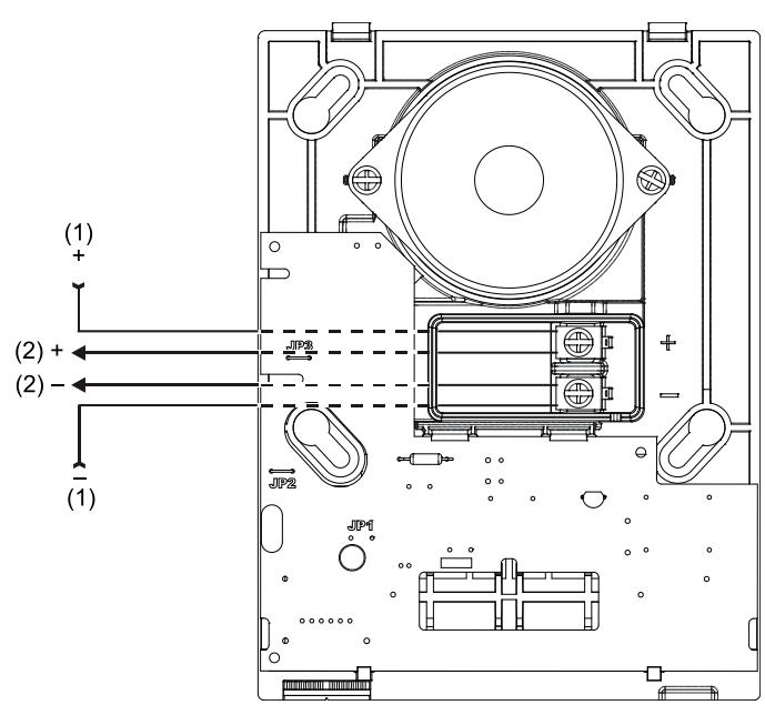
- (1) From NAC output
- (2) To next device or EOL
Note: Polarity is shown in the active condition.
Maintenance
Caution: To maintain the required agency listings, do not change factory-applied finishes.
This unit is not serviceable or repairable. Should the unit fail to operate, contact the supplier for a replacement.
Perform a visual inspection and an operational test twice a year or as directed by the local authority having jurisdiction.
Specifications
| Operating voltage | 24 VDC or 24 VFWR [1] | |
|---|---|---|
| Current | ||
| Alarm | 166 mA at 16 VDC, 215 mA at 16 VFWR | |
| Operating | See Table 4 | |
| Sound level output | See Table 2 and Table 3 | |
|
Audible directional
characteristics |
See Table 5 and Table 6 | |
| Wire size | 12 to 18 AWG (1.0 to 4.0 mm²) | |
|
Compatible electrical
boxes |
Standard 4 in. square box 1-1/2 in. (38 mm),
2-1/8 in. (54 mm) deep box, or G4B/G4RB surface mount box |
|
| Operating environment | ||
| Temperature | 32 to 120°F (0 to 49°C) | |
| Relative humidity | 0 to 93% noncondensing | |
[1] This device was tested to the Regulated 24 DC/FWR operating voltage limits of 16 V and 33 V. Do not apply 80% and 110% of these values for system operation.
Table 2: UL sound level output (dBA) [1]
| Signal and voltage | Low | High | |
|---|---|---|---|
| 16 VDC | 72.4 | 76.0 | |
| 24 VDC | 72.3 | 75.7 | |
| 33 VDC | 73.3 | 75.4 | |
| 16 VDC | 75.7 | 79.8 | |
| 24 VDC | 76.1 | 78.6 | |
| 33 VDC | 75.4 | 78.8 | |
[1] UL 464: Sound level output at 10 ft. (3.05 m) measured in a reverberant room
Table 3: Nominal sound level output (dBA, temporal tone) [1]
| Voltage | Low | High | |
|---|---|---|---|
| 16 VDC | 84.0 | 85.5 | |
| 24 VDC | 83.9 | 85.4 | |
| 33 VDC | 83.7 | 85.5 | |
| 16 VFWR | 83.7 | 86.1 | |
| 24 VFWR | 83.9 | 85.9 | |
| 33 VFWR | 84.0 | 85.9 | |
[1] Measured in an anechoic chamber at 10 ft. (3.05 m)
Table 4: Nominal operating current in RMS (mA)
| Signal and voltage | Low | High | |
|---|---|---|---|
| Temporal | 16 VDC | 86 | 166 |
| 24 VDC | 43 | 112 | |
| 33 VDC | 36 | 87 | |
| 16 VFWR | 97 | 215 | |
| 24 VFWR | 78 | 159 | |
| 33 VFWR | 76 | 140 | |
| Continuous | 16 VDC | 36 | 160 |
| 24 VDC | 45 | 109 | |
| 33 VDC | 36 | 86 | |
| 16 VFWR | 92 | 212 | |
| 24 VFWR | 80 | 168 | |
| 33 VFWR | 77 | 141 | |
VDC = Volts direct current, regulated and filtered
VFWR = Volts full wave rectified
Table 5: Audible directional characteristics (horizontal pattern)
| Angle (°) [1] | Output (dB) [2] |
|---|---|
| 0 | 85 |
| +90 | 82 |
| -90 | 82 |
[1] Angles are measured from a perpendicular axis; positive angles to the right.
[2] Peak output at 16 VDC, set for steady tone.
Table 6: Audible directional characteristics (vertical pattern)
| Angle (°) [1] | Output (dB) [2] |
|---|---|
| 0 | 85 |
| +90 | 82 |
| −90 | 82 |
[1] Angles are measured from a perpendicular axis; positive angles are up.
[2] Peak output at 16 VDC, set for steady tone.
Regulatory information
| Manufacturer |
Edwards, A Division of UTC Fire & Security
Americas Corporation, Inc. 8985 Town Center Parkway, Bradenton, FL 34202, USA |
|---|---|
|
Year of
manufacture |
The first two digits of the date code (located on
the product identification label) are the year of manufacture. |
| UL | Regulated 24 DC and 24 FWR |
|
North American
standards |
UL 464 |
Contact information
For contact information, see www.edwardsutcfs.com.