Edwards Signaling Genesis Chime Installation Instructions
Open the original PDF document
View PDFProduct information
The Genesis Chime is an audible fire alarm notification appliance designed for indoor walls. See Table 1 for a list of model numbers.
The chime includes field configurable jumper options for selecting the desired dB output, steady or temporal chime output, and constant non-coded voltage or single-stroke coded voltage operation. A Genesis Signal Master is required when chimes are configured for coded operation. See Table 2 for a list of compatible synchronization modules.
Install this device in accordance with applicable requirements in the latest editions of the NFPA codes and standards and in accordance with the local authorities having jurisdiction.
Table 1: Model numbers
| Model description | Model numbers | |
|---|---|---|
|
Chime,
white |
ADTG1-C
EG1-C G1-C G1-C-LG |
MG1-C
XLSG1-C ZG1-C |
|
Chime,
white, with FIRE marking |
ADTG1F-C
EG1F-C G1F-C G1F-C-LG |
MG1F-C
XLSG1F-C ZG1F-C |
|
Chime,
red |
ADTG1R-C
EG1R-C G1R-C G1R-C-LG |
MG1R-C
XLSG1R-C ZG1R-C |
|
Chime,
red, with FIRE marking |
ADTG1RF-C
EG1RF-C G1RF-C G1RF-C-LG |
MG1RF-C
XLSG1RF-C ZG1RF-C |
|
Trim plate,
white |
ADTG1T
EG1T G1T G1T-LG |
MG1T
XLSG1T ZG1T |
Table 1: Model numbers
| Model description | Model numbers | |
|---|---|---|
|
Trim plate,
red |
ADTG1RT
EG1RT G1RT G1RT-LG |
MG1RT
XLSG1RT ZG1RT |
Table 2: Compatible synchronization modules
| Model names | Model numbers | |
|---|---|---|
|
Auto-Sync Output
Module |
SIGA-CC1S |
SIGA-MCC1S
SIGA-CC1S-LG SIGA-MCC1S-LG |
|
Signal Master
snap-on piggyback (1-gang) |
ADTG1M
EG1M G1M G1M-LG |
MG1M
XLSG1M ZG1M |
|
Signal Master - Remote
Mount |
ADTG1M-RM
EG1M-RM G1M-RM G1M-RM-LG |
MG1M-RM
XLSG1M-RM ZG1M-RM |
Note: Synchronization module requirements are determined by your application
Specifications
Operating voltage
Regulated 16 to 33 Vdc, 16 to 33 Vfwr
This device was tested to the regulated 24 Vdc/fwr operating voltage limits of 16 V and 33 V. Do not apply 80% and 110% of these values for system operation.
Operating current: See Table 2 Sound level output: See Table 3
Signals
Steady: 60 strokes per minute Temporal: 3-stroke pattern
Coded: Maximum 60 strokes per minute
Operating modes
Non-coded: Continuous voltage
Coded: Single-stroke controlled by voltage
Default settings Signal: Steady
Sound level output: High db Operation: Non-coded
Wire size: 12 to 18 AWG (2.50 to 0.75 sq mm)
Compatible electrical boxes
North American 2-1/2 in (64 mm) deep 1-gang box Standard 4 in square box 1-1/2 in (38 mm), 2-gang, or 4 in
octagonal with G1T or G1RT trim accessory
Operating temperature range: 32 to 120 °F (0 to 49 °C)
Operating humidity range: 0 to 93% RH
Agency listings: Meets or exceeds UL464 Seventh Edition for private mode
Table 2: Operating current in (Amp RMS)
| High db | Low db | |
|---|---|---|
| 16 Vdc | 0.030 | 0.019 |
| 24 Vdc | 0.043 | 0.026 |
| 33 Vdc | 0.045 | 0.027 |
| 16 Vfwr | 0.060 | 0.040 |
| 24 Vfwr | 0.076 | 0.049 |
| 33 Vfwr | 0.081 | 0.055 |
Vdc = Volts direct current, regulated and filtered Vfwr = Volts full wave rectified.
Table 3: Sound level output (dBA)
| Signal and vo | oltage | High db | Low db |
|---|---|---|---|
| Temporal | 16 Vdc | 56.9 | 52.5 |
| 24 Vdc | 59.8 | 54.8 | |
| 33 Vdc | 60.1 | 55.0 | |
| Steady | 16 Vdc | 58.2 | 52.8 |
| 24 Vdc | 60.8 | 55.6 | |
| 33 Vdc | 61.3 | 56.1 |
dBA = Decibels, A-weighted
UL464: Sound level output at 10 ft (3.05 m) measured in a reverberant room.
Installation instructions
Caution: Electrical supervision requires the wire run to be broken at each terminal. Do not loop the signaling circuit field wires around the terminals.
To install the chime:
- Remove the cover by depressing both tabs on the top of the unit with a small screwdriver and twisting slightly.
- Set the chime signal, sound output level, and desired operation settings. See Figure 1.
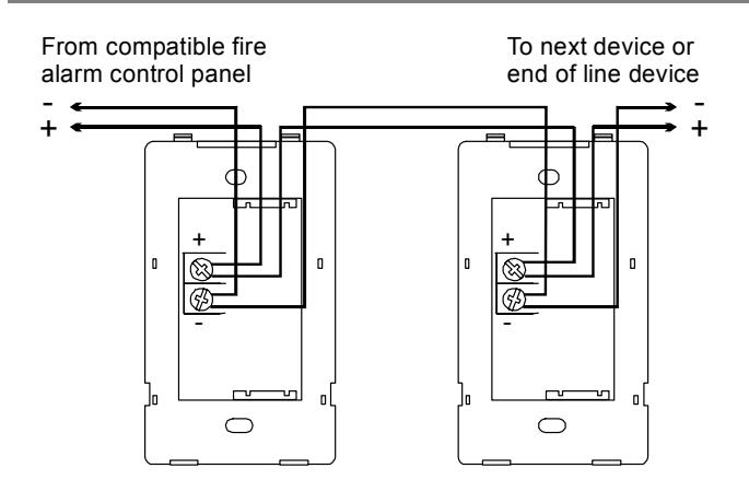
- Connect the chime terminals to the signal circuit field wiring. You must observe polarity for the unit to function properly.
For constant non-coded voltage operation, see Figure 2. For single-stroke coded voltage operation, see Figure 3.
- Mount the unit onto a compatible electrical box, making sure not to over tighten the mounting screws.
- 5. Replace the cover by aligning at the bottom, then snapping in at the top.
- 6. Test the unit for proper operation.
Maintenance
This unit is not serviceable or repairable. Should the unit fail to operate, contact the supplier for replacement.
Perform a visual inspection and an operational test twice a year or as directed by the local authority having jurisdiction.
from steady to temporal cut from circle J1 to edge of circuit board output level from high dB to low dB cut J3 trace between holes
To change the chime operation from non-coded to coded (single-stroke) cut from circle J2 to edge of circuit board
To change the chime sound
Figure 1: Chime settings
To change the chime signal
Note: Polarity shown in alarm condition
Figure 2: Constant non-coded voltage operation
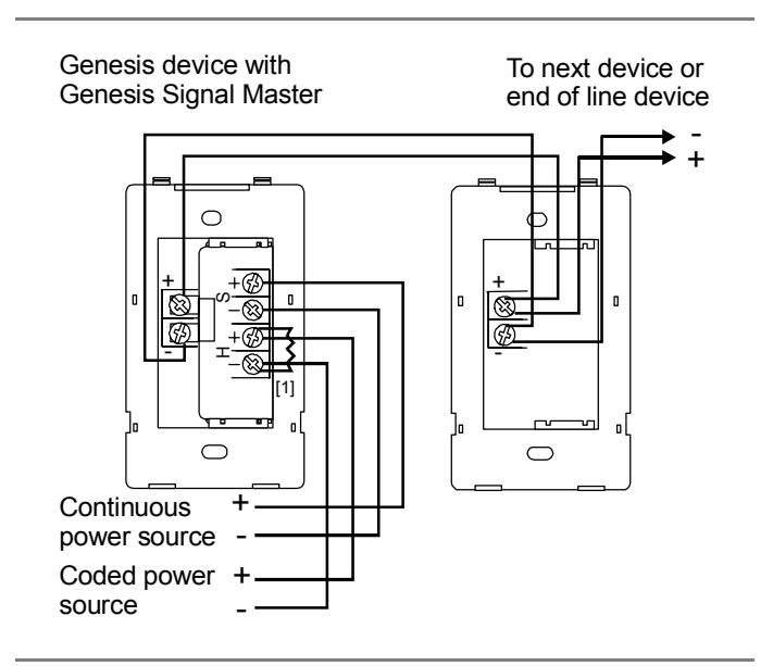
Figure 3: Single-stroke coded voltage operation