Edwards Signaling FireShield 1 Zone Installation Manual
Open the original PDF document
View PDFFireShield Single-Zone Panel Installation and Operating Instructions
Product description
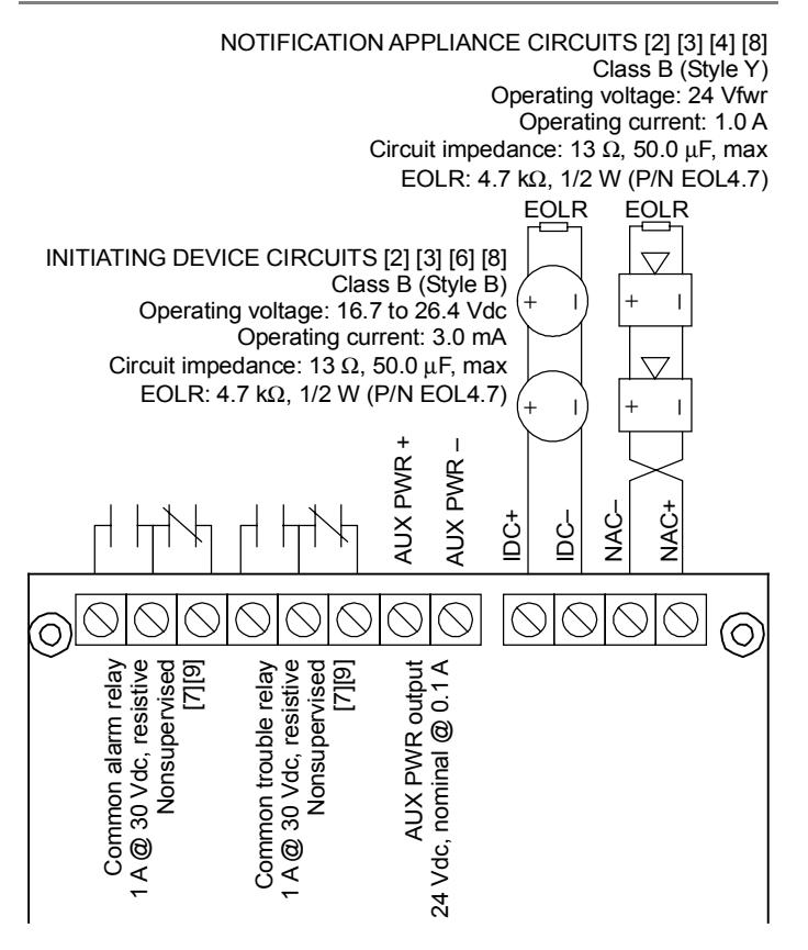
The FireShield single-zone panel has one initiating device circuit (IDC) and one notification appliance circuit (NAC). The panel is configured for Class B operation only.
Specifications
IDC zones: 1 Class B NAC zones: 1 Class B NAC voltage rating: 24 Vfwr NAC max current: 1.0 A
Auxilliary power: 24 Vdc at 0.1 A auxiliary power with reset
option
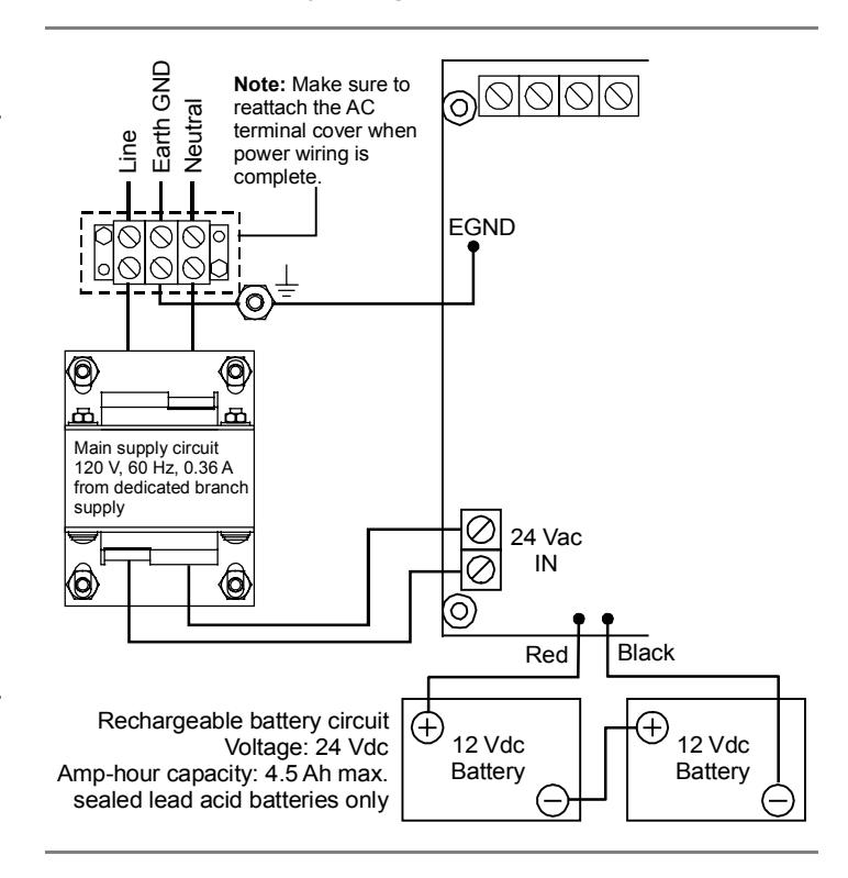
Primary power: 120 Vac 60 Hz, 0.36 A
Alarm contact: Form C 30 Vdc at 1 A (resistive load) Trouble contact: Form C 30 Vdc at 1 A (resistive load)
Standby batteries: 4.5 Ah max.
Operating environment
Temperature: 32 to 120 °F (0 to 49 °C) Humidity: 93% RH, noncondensing
Controls and indicators
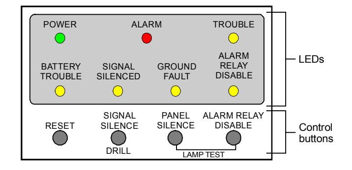
LEDs
Power: On when the panel has AC power.
Alarm: On steady (latched) when there is an active alarm event on the IDC.
Trouble: On when there is a fault with a monitored circuit or system component, or when a circuit is disabled.
Battery Trouble: Flashes for charger or low battery trouble. Steady means placement trouble. Also places the panel in the trouble state.
Signal Silenced: On steady indicates that the NAC circuit is turned off (silenced) but the panel is still in alarm.
Ground Fault: On steady during an active ground fault. (Also places the panel in the trouble state.)
Alarm Relay Disable: On when there is a disabled circuit. (Also places the panel in the trouble state.)
Control buttons
Reset: Resets the panel.
Signal Silence and Drill
Alarm mode: Silences active notification appliances. Pressing Signal Silence a second time unsilences the NAC. The Signal Silenced LED indicates when the panel is in alarm and operating with notification appliances silenced. Visible appliances may or may not turn off when Signal Silence is pressed depending on JP1/JP2 settings.
Normal mode: Activates the drill function. Turns notification appliances on according to JP1/JP2 settings but does not place the panel in alarm or activate the alarm relay. Pressing Drill a second time turns off the drill function.
Panel Silence: Silences the panel sounder during an active trouble or alarm event.
Alarm Relay Disable: Deactivates the alarm relay and prevents it from activating in a future alarm event. Pressing Alarm Relay Disable places the panel in the trouble state.
Lamp test
Panel Silence and Alarm Relay Disable: Press the Panel Silence and Alarm Relay Disable buttons simultaneously to do a panel lamp test. This lets you verify proper operation of the LEDs.
Installation checklist
- Prepare the site: Make sure the installation location is free from construction dust and debris and extreme temperature ranges and humidity.
- Unpack the equipment
- Install the cabinet: See "Installing the cabinet."
- Remove the metal terminal shield: Remove and save the four screws that hold the terminal shield in place.
- Set the panel jumpers: See "Jumper setup."
- Review wire routing: See "Wire routing."
- Connect the field wiring: See "Wiring diagrams" or the panel label. Meter for opens, grounds, and shorts before connecting.
- Connect AC power and ground: See "Wiring diagrams" or the panel label. The panel can not be started on batteries only.
WARNING: Make sure that the AC power circuit breaker is off before connecting wires to the terminal block.
- Connect batteries: See "Wiring diagrams" or the panel label.
- Install the metal terminal shield: Be careful to align the terminal shield correctly over the LEDs and buttons. Use the four screws that you removed earlier.
- Test for proper operation: See "Operating the panel."
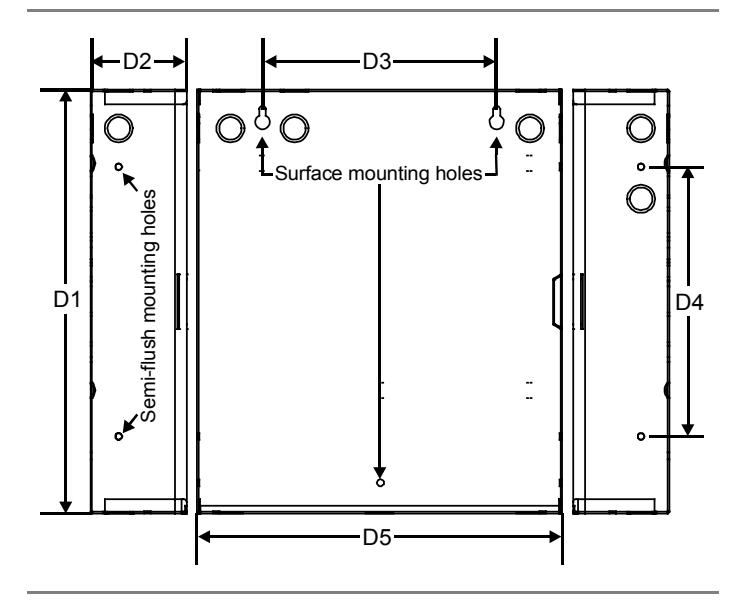
Installing the cabinet
Cabinets can be surfaced mounted. See the figure and table below for framing and mounting dimensions.
To surface mount the cabinet:
- 1. Position the cabinet on the finished wall surface.
- 2. Fasten the cabinet to the wall surface where indicated.
| D1 | D2 | D3 | D4 | D5 |
|---|---|---|---|---|
| 13.0 in | 3.0 in | 6.0 in | 7.0 in | 11.0 in |
| (33.0 cm) | (7.6 cm) | (15.2 cm) | (17.8 cm) | (28.0 cm) |
Jumper setup
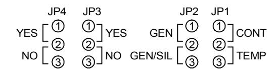
Jumper layout as seen on the circuit board
JP1 and JP2: NAC output type
Description: Controls the output of the NAC.
Default: Genesis (with horn silence), with no jumper installed.
Options (choose one)
Continuous Genesis Temporal Genesis (with horn silence)
Continuous: For strobes and notification appliances that selfgenerate a temporal pattern or where temporal pattern is not required.
Temporal: Universal 3-3-3 pattern required for evacuation signals by NFPA 72. Used when notification appliances are not capable of self-generating a temporal pattern.
Genesis: Used with Genesis and Enhanced Integrity horns and strobes. Genesis and Enhanced Integrity appliances maintain
strobe synchronization per UL 1971. Both horns and strobes will silence when alarm silence is activated.
Genesis (with horn silence): Used with Genesis and Enhanced Integrity horns and strobes. Genesis and Enhanced Integrity appliances maintain synchronization per UL 1971. For Genesis devices, this allows connected horns to be silenced while strobes on the same 2-wire circuit continue to flash until the panel is reset. For Enhanced Integrity devices, both horns and strobes will remain activated until the panel is reset.
JP3: Aux power reset
Description: Causes a temporary interruption of aux power when Reset is pressed. This is so that four-wire smoke detectors can be reset. If this is not set, pressing Reset has no effect on the aux power output.
Default: No aux reset, with no jumper installed.
Options
1 2 3 Yes (aux reset) No (no aux reset)
Aux reset: Resettable 24 Vdc on AUX PWR terminals.
No aux reset: Continuous 24 Vdc on AUX PWR terminals.
JP4: IDC type
Description: Selects the type and functionality of the IDC.
Default: No alarm verification, with no jumper installed.
Options
1 2 3 Yes (verify alarm) No (no alarm verification)
Verify alarm: For circuits with smoke detectors and contact devices. 2-wire smoke detector activations are verified (delayed and confirmed) before activating an alarm. 4-wire smoke detectors and contact devices are not verified and immediately considered as alarms. A circuit can not be restored until devices are restored to normal and the panel is reset. See the FireShield Single Zone ULI and ULC compatibility lists (P/N 3100592) for restrictions.
No alarm verification: For circuits with smoke detectors and contact devices. All activations are immediately considered as alarms. A circuit cannot be restored until devices are restored to normal and the panel is reset.
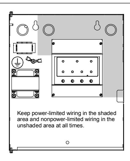
Wire routing
All wiring is power-limited except for AC power and battery wiring. All wiring is supervised unless noted otherwise.
Wiring diagrams
The following diagrams show field wiring, AC power and battery wiring, and RTU wiring.
Field wiring
AC power and battery wiring
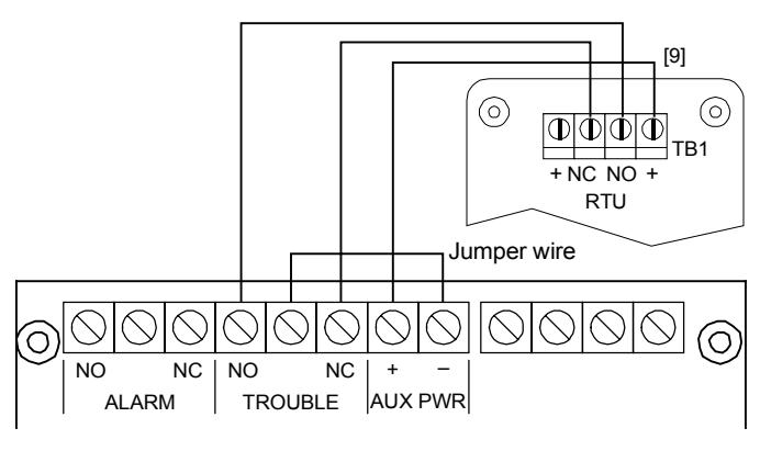
RTU wiring
Notes
The following notes match the wiring label notes inside the panel, and are not numbered sequentially.
- [2] Class B wiring only
- [3] Listed EOLRs must be installed as shown for proper supervision
- [4] Marking indicates output signal polarity when the circuit is active. Polarity reverses when the circuit is not active. Wire notification appliances accordingly. Notification appliance polarity shown in active state.
- [6] When the IDC is programmed for alarm verification, both automatic and manually activated alarm initiating devices can be connected simultaneously. Manually initiated devices will not be verified (delayed).
- [7] Relay circuits can only be connected to power-limited sources
- [8] Installation limits under jurisdiction of local authority
- [9] Contacts shown in normal condition
Operating the panel
The panel operates in normal mode in the absence of any alarm or trouble events. In normal mode, the control panel monitors the system.
The panel operates in off-normal mode any time an event is introduced into the system. When this happens, the panel:
- Changes contact positions on appropriate common relays
- Activates alarm outputs (for alarm events only)
- Turns on the appropriate LEDs and the panel buzzer
- Executes the appropriate output response for the input that signaled the event
Resetting the panel
Pressing Reset places the panel in the reset state. The panel should not be reset until the appropriate authority has determined that the hazard is no longer present.
When you reset the panel:
- All LEDs on the panel light for two seconds
- The trouble and power LEDs remain on for the remainder of the reset
- When reset is complete, the trouble relay returns to the normal state and the trouble LED turns off
In this state:
- All panel indicators are temporarily cleared
- All notification appliances are turned off
- All latched IDCs are cleared
- Alarm and trouble relays are returned to the inactive state
- Auxiliary power (if programmed as resettable) momentarily turns off
At the conclusion of the reset, if the IDC is in an off-normal state, the panel treats the event as a new event and activates the responses described above.
To reset the panel:
1. Press the Reset button.
Silencing the panel buzzer
Pressing the Panel Silence button silences the buzzer on the panel. Once panel silence is initiated, and the trouble that caused the buzzer to activate has not restored (if it's nonlatching), the buzzer reactivates automatically after 24 hours.
To silence the panel buzzer:
- 1. Press the Panel Silence button.
- 2. Determine the type of condition that caused the buzzer to sound: alarm or trouble.
- 3. Determine the cause of the condition.
Silencing notification appliances
Pressing the Signal Silence button turns off all audible devices.
When you silence the signals, the Signal Silenced LED lights, indicating that the notification appliances are off. The panel does not indicate a trouble condition. If GENESIS with horn silence is set, Signal Silence silences only the horns.
WARNING: The notification appliances should not be silenced until the building is fully evacuated and the cause of the alarm has been determined.
To silence notification appliances:
1. Press the Signal Silence button.
Re-sounding an alarm condition (NACs)
Pressing the Signal Silence button again turns the audible devices back on if they were silenced.
To re-sound notification appliances:
1. Press the Signal Silence button again.
Disabling the alarm relay
Pressing the Alarm Relay Disable button deactivates the alarm relay and prevents the relay from responding to any status change from the IDC. When you disable the alarm relay:
- The Alarm Relay Disable LED lights
- The panel buzzer activates
- The trouble relay changes state
Resetting the panel has no effect on the disabled relay, but removing all power from the panel clears the disable and enables the relay.
To disable the alarm relay:
1. Press the Alarm Relay Disable button.
To re-enable the alarm relay:
1. Press the Alarm Relay Disable button.
Using the drill command
You can use the drill command to activate the notification appliance circuit. Pressing Signal Silence & Drill activates all audibles and visibles, but does not activate the Alarm relay. Drill will not operate with an active alarm event at the panel.
To perform a fire drill:
- 1. Press the Signal Silence & Drill button.
- 2. To stop the drill, press the Signal Silence & Drill button.
Battery calculation worksheet
Use this worksheet to determine the minimum amperage capacity required for the panel's standby battery. You can obtain operating current requirements for notification appliances from their respective installation sheets.
|
Standby
Current (mA) |
Alarm
Current (mA) |
||||
|---|---|---|---|---|---|
| Base panel [1] | 50 | 165 | |||
| RTU (Aux current) | 10 | 13 | |||
| IDC detector current [2] [3] [4] [6] | 75 | ||||
| NAC load [see NAC voltage drop] | 0 | ||||
| Total current | |||||
| Required standby and alarm time | × |
Enter
standby time in hours |
× | Alarm time |
5 min = 0.083 hr
10 min = 0.167 hr 15 min = 0.250 hr 30 min = 0.500 hr |
|
mAh
+ |
mAh
= |
mAh | |||
| Battery amp hour total = |
÷ 1000
Ah × 1.2 |
||||
| Minimum battery size [5] = | Ah |
Notes
- [1] Base panel includes main controller board with no load, only EOL resistors (standby current: 50 mA, alarm current: 85 mA)
- [2] See the FireShield UL and ULC Compatibility List (P/N 3100592) for the maximum number of detectors per IDC
- [3] See the FireShield UL and ULC Compatibility List (P/N 3100592) for detector current ratings
- [4] Maximum supervisory IDC current can not exceed 3.0 mA
- [5] The maximum battery size the panel can charge is 4.5 Ah
- [6] Use maximum value or actual calculated value (Detector quantity x detector current (mA) = Total standby current for IDC). An active pull station draws 75 mA.
Notification appliance voltage drop calculation
| NAC voltage drop calculations | ||||||
|---|---|---|---|---|---|---|
| Circuit length | Total circuit current [2] | Wire resistance per 1000 ft [1] | Voltage drop | |||
| feet | x | amps | x | Ω | ÷ 1000 = |
| Panel voltage | Voltage drop | End of line voltage [3] | Voltage drop | Panel voltage | Voltage drop % | ||||
|---|---|---|---|---|---|---|---|---|---|
| [4] | – | = | ÷ | [4] | = |
Notes
- [1] Use 3.5 Ω for 12 AWG and 2.5 sq mm wire, 5.2 Ω for 14 AWG and 1.5 sq mm wire, 8.0 Ω for 16 AWG and 1.0 sq mm wire, and 13.0 Ω for 18 AWG and 0.75 sq mm wire
- [2] Use the 20 Vfwr Average Operating Current ratings found on the installation or catalog sheet of each device
- [3] Cannot drop below 17 Vdc
- [4] 18.9 V min. NAC output voltage
Notification appliance circuit maximum wire length calculation
Use this worksheet to determine the maximum wire length of a notification appliance circuit.
Wire length matrix
Wire lengths in the following table are based on a voltage drop of 1.9 volts or 10% of the total load at the end of the line.
| Maximum wire length | ||||||
|---|---|---|---|---|---|---|
|
Current
required |
18 AWG | 16 AWG | 14 AWG | 12 AWG | ||
| 0.25 | 584 | 950 | 1460 | 2170 | ||
| 0.50 | 292 | 474 | 730 | 1084 | ||
| 0.75 | 194 | 316 | 486 | 722 | ||
| 1.00 | 146 | 236 | 364 | 542 | ||
| Maximum signal loss allowed [1] | V | |
|---|---|---|
| × | 1000 | |
| Wire resistance per 1000 ft/pair [2] | ÷ | Ω |
| Total operating current required [3] | ÷ | A |
| Maximum circuit length | ft |
Notes
- [1] 1.9 V max. voltage drop
- [2] Use 3.5 Ω for 12 AWG and 2.5 sq mm wire, 5.2 Ω for 14 AWG and 1.5 sq mm wire, 8.0 Ω for 16 AWG and 1.0 sq mm wire, and 13.0 Ω for 18 AWG and 0.75 sq mm wire
- [3] Use the 20 Vfwr Average Operating Current ratings found on the installation or catalog sheet of each device
Preventive maintenance
Before commencing testing, notify all areas where the alarm sounds and off-premises locations that receive alarm and trouble transmissions that testing is in progress.
- Records of all testing and maintenance shall be kept as required by the authority having jurisdiction.
-
Required tools:
- -Slotted screwdriver, insulated
- -Digital multimeter
- -1.1 kΩ, 1 W resistor
- -12 in (30.5 cm) jumper lead with alligator clips
- -Panel door key
- -Sound level meter
- A complete check of installed field wiring and devices should be made at regular intervals in accordance with NFPA 72, Canadian Electrical Code Part I, ULC S524, and S536 requirements. This includes testing all alarm initiating devices and circuits and any off-premises connections.
- Panel operation should be verified in the alarm and trouble modes.
- To ensure that the panel can be powered when primary power is lost, the batteries should be periodically inspected, tested, and replaced (at a minimum) every four years.
Preventive maintenance schedule
Refer to NFPA 72, Chapter 7 Inspection, Testing, and Maintenance, Canadian Electrical Code Part I, ULC S524, or ULC S536 for more information on required inspection and testing methods and frequency of fire alarm systems and devices. For detector sensitivity and functionality testing, refer to the detector manufacturer's installation instructions.
Canadian tests for grounds, opens, and shorts
ULC requires that you test ground fault, open circuit, and short circuit indications.
For ground fault tests, directly short one leg of the circuit to chassis ground. The Ground Fault and Trouble LEDs must light.
For NAC and IDC open circuit tests, remove the EOL resistor from the last device on the circuit. The Trouble LED must light.
For NAC short circuit testing, place a short across the NAC output. The trouble LED must light.
For AUX power short circuit testing, place a short across the +24 V and -24 V at the panel. The trouble LED must light.
Contact information
Phone: (941) 739-4200
FireShield Single-Zone Fire Alarm Control Panel Operating Instructions
For additional information, refer to the FireShield Single-Zone Panel Installation and Operating Instructions P/N 3100589.
RESPONDING TO ALARM SIGNALS
- 1. Evacuate the area.
- 2. Notify the proper authorities immediately and state the nature and location of the emergency.
- 3. Be prepared to provide directions to firefighters when they arrive.
TO SILENCE ALARM NOTIFICATION SIGNALS
WARNING! Alarm notification signals should not be silenced until after all occupants have been evacuated.
Note: Panel programming may not allow visual notification appliances to turn off until the panel is reset.
1. Press Signal Silence & Drill.
The Signal Silenced LED turns on and all audible notification circuits turn off. New alarm events turn the notification circuits back on.
TO RETURN THE SYSTEM TO NORMAL AFTER AN ALARM EVENT
- 1. Make sure all smoke detectors are free from smoke and all manual pull stations are reset.
- 2. Press Reset.
TO INITIATE A FIRE DRILL
1. Press Signal Silence & Drill.
All audible notification circuits turn on.
TO PERFORM A LAMP TEST
1. Press and hold the Panel Silence and Alarm Relay Disable buttons simultaneously.
RESPONDING TO TROUBLE SIGNALS
- 1. Silence the panel buzzer.
- 2. Investigate the cause of the trouble and notify the authorized service personnel immediately.
TO SILENCE THE PANEL BUZZER
1. Press Panel Silence.
The buzzer turns off. Any new events turn the buzzer back on. Trouble conditions not cleared resound the buzzer after a predetermined time.
WARNING! Trouble conditions may affect the panel's ability to provide early detection and indication of a fire. Clear trouble conditions immediately.
PERIODIC TEST RECOMMENDATIONS
See "Preventive Maintenance," in the FireShield Single-Zone Panel Installation and Operating Instructions for test instructions and references.
| Installed by |
|---|
| Name: |
| Company: |
| Address: |
| Phone: |
| Per NFPA 72 |
| Protected Premises Fire Alarm System, Local |
| Date: |
| For service contact |
| Company: |
| Address: |
| Phone: |
| Acceptance Inspection by |
| Date: |