Edwards Signaling FSC Quick Reference Card
Open the original PDF document
View PDFE-FSC c o n v e n t i o n a l s m a l l b u i l d i n g f i r e a l a r m s o l u t i o n s
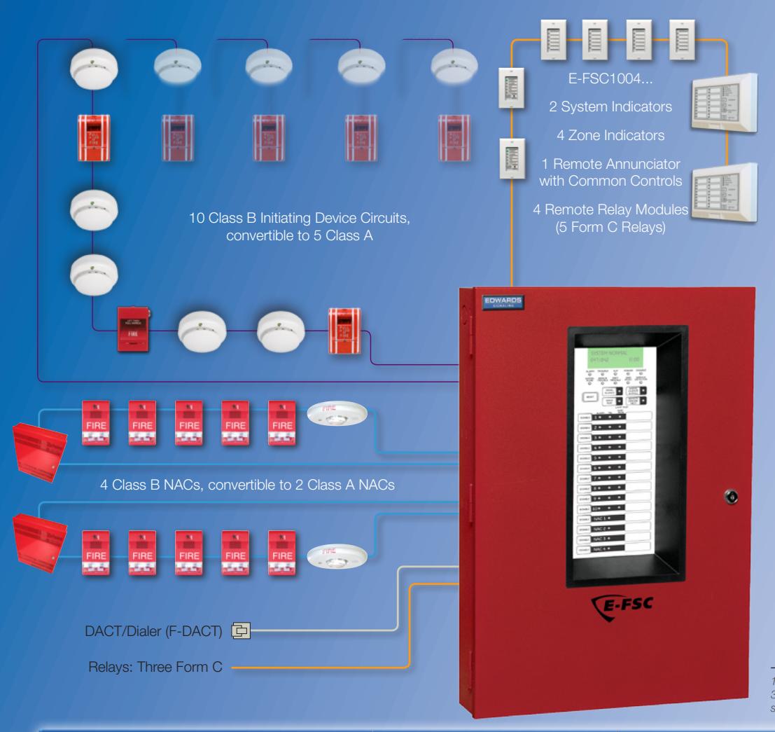
The simplicity of conventional wiring with valuable features found only among high-end systems.
- CleanMe® feature provides remote annunciation if compatible detector drifts out of UL limits
- Automatic drift compensation extends detector life
- Precision UL 1971 signal synchronization and optional audible silence over just two wires
- Up to 7 amps available NAC power cuts equipment costs
- Fully integrated upload/download communications enables PC programming and off-premise monitoring
- Zone or NAC pairs convertible to single Class A circuits
- Combination Waterflow and Supervisory zones
- NACs programmable by zone and individually selectable for continuous, temporal or coded outputs, or Genesis protocol
10-zone model illustrated. 5-zone and 3-zone models also available.See table for specifications.
| Specifications | E-FSC1004 | E-FSC502 | E-FSC302 | ||||||||
|---|---|---|---|---|---|---|---|---|---|---|---|

Quick Reference
Consult relevant literature for full listing of available models and options.
| Control Par | Control Panels | ||||
|---|---|---|---|---|---|
| E-FSC1004RD |
Conventional Fire Alarm Control
Panel with dialer, 10 Class B IDCs and 4 Class B NACs |
||||
| E-FSC502RD |
Conventional Fire Alarm Control
Panel with dialer, 5 Class B IDCs and 2 Class B NACs |
||||
| E-FSC302RD |
Conventional Fire Alarm Control
Panel with dialer, 3 Class B IDCs and 2 Class B NACs |
||||
| F-TRIM10R |
Semi-Flush Mount Trim Kit for
E-FSC1004R |
||||
| F-TRIM35R |
Semi-Flush Mount Trim Kit for
E-FSC502R and E-FSC302R |
||||
| BC-1R | Battery Cabinet, red | ||||
| 12V6A5 | 7.2 Ah Batteries | ||||
| 12V10A | 11.0 Ah Batteries | ||||
| 12V17A | 18 Ah Batteries | ||||
| Option Cards | |||
|---|---|---|---|
| F-XTR120 |
Expander X-Former, 120 Vac,
E-FSC1004RD only |
||
| CTM | City Tie Module (Requires 4" sq. box or 2-gang) | ||
| RPM |
Reverse Polarity Module, Requires
MFC-A or other listed FA enclosure |
||
| FSRRM24 |
Remote Relay Module – 5 Form C
relays, Config. IDCs 1-5, or 6-10, or common system indicators, Requires MFC-A or other listed FA enclosure |
||
| Remote | Annunciation | |
|---|---|---|
| FSRSI |
Remote System Indicator – Power,
Alarm, Super., Trouble, and Grnd LEDs (Single Gang trim included) |
|
| FSRZI-A |
Remote Zone Indicator – 5 Red
LEDs for 5 IDCs (Single Gang trim included) |
|
| FSRZI-SA |
Remote Zone Indicator – 5 Bi-Color
LEDs (Red/Yellow) for 5 IDCs (Single Gang trim included) |
|
| FSAT-2 | Ann. Trim Plate, 2-Gang | |
| FSAT3 | Ann. Trim Plate, 3-Gang | |
| FSRA10 |
Remote Annunciator 10-Zone Bi-
Color LEDs (Red/Yellow) w/ System Indicators for E-FSC1004RD (4" sq. box mnt.) |
|
| FSRA10C |
Remote Annunciator
10-Zone Bi-Color LEDs (Red/ Yellow) w/ System Indicators & Controls for E-FSC1004RD (4" sq. box mnt.) |
|
| FSUIM | Graphic Drive/Interface providing | |
| Power Su | pplies |
|---|---|
| EBPS6A | 6.5 Amp Booster Power Supply |
| EBPS6A | 6.5 Amp Booster Power Supply |
| EBPS10A | 10 Amp Booster Power Supply |
| 12V6A5 | 7.2 Ah Batteries |
| 12V10A | 11.0 Ah Batteries |
| BC-1R - Red | Battery Cabinet |
System Indicators and Controls
| 2-Wire De | etectors and Bases | |
|---|---|---|
| 511C | Photoelectric Smoke Detector, Base | |
| included | ||
| EO4D | Photoelectric Smoke with CleanME | |
| 521B | Feature, Base included | |
| Conventional photoelectric smoke | ||
| TS7-2 | detector, 6" 3-terminal base, | |
| 12/24VDC. 3-terminal base 701U. | ||
| TS7-2T | Conventional photoelectric smoke | |
| detector, FS & RoR heat, remote | ||
| alarm/trouble LED., 12/24VDC. | ||
| Heat Detectors | ||||
|---|---|---|---|---|
| 281B-PL | 135* Fixed / RoR Heat Detector | |||
| 282B-PL | 194* Fixed / RoR Heat Detector | |||
| 302-AW-135 |
135* Fixed / RoR Moisture Proof
Heat Detector |
|||
| 302-AW-194 |
194* Fixed / RoR Moisture Proof
Heat Detector |
|||
| 2-Wire Duct Detectors | ||||
|---|---|---|---|---|
| SD-2W | Conventional SuperDuct Detector | |||
| SD-Txx | Sampling Tubes for SuperDuct | |||
| SD-TRK4 | Remote Test Stations for SuperDuct | |||
| Manual Stations | |||
|---|---|---|---|
| 278B-1110 | Double Action Pull Station, Term., | ||
| 2700 1110 | Tool Reset, Lexan | ||
| 278B-1120 | Double Action Pull Station, Term., | ||
| Key Reset, Lexan | |||
| 276B-RSB | Surface Mount Box, Red | ||
| MPSR1- | Weatherproof Manual Station, | ||
| S45W-GE | c/w backbox | ||
| Strobes, F | lorns |
|---|---|
| EG1RF-VM |
Wall Strobe, 15-110 cd, Marked
"Fire", 24VDC, red |
| EG1RF-HDVM |
Wall Horn/Strobe, 15-110 cd,
Marked "Fire", 24VDC, red |
| EG1RF-HD |
Wall Horn, Temporal, High/Low dB,
Marked "Fire", 24VDC, Red |
| EG1RT | Genesis Trim Plate (for 2-gang or 4" sq. boxes), red |
| EGCF-VM |
Ceiling Multi-cd Strobe, 15-95 cd,
Marked "Fire", red |
| EGCF-VMH |
Ceiling Multi-cd Strobe, 95-177 cd
Marked "Fire", red |
| EGCF-HDVM |
Ceiling Multi-cd Horn-Strobe, 75-
95 cd, Marked "Fire", red |
| EGCF-HDVMH |
Ceiling Multi-cd Horn-Strobe,
95-177 cd, Marked "Fire", red |
| CS405-8A-T | Weatherproof Strobe, 110 cd |
|
2452THS-
110-R |
Weatherproof Horn/Strobe, 110 cd |
| 449 | Weatherproof Box for CS405 strobes |
| 2459WPB-R | Weatherproof Surface Box, red |
| Doorhold | ers |
|---|---|
| 1501-AQN5 | Single Door, Floor Mounted |
| 1502-AQN5 | Double Door, Floor Mounted |
| 1504-AQN5 | Long Catch Plate, Flush Wall Mnt. |
| 1505-AQN5 | Short Catch Plate, Flush Wall Mnt. |
| 1508-AQN5 | Surface, Wall Mounted |
| Single SPDT relay. Contact Rating |
| 10 Amps @ 115Vac and Coil Power |
| 24 Vac, 24Vdc, 115Vac or 230Vac. |
| Single DPDT relay. Contact Rating |
| 10 Amps @ 115Vac and Coil Power |
| 24 Vac, 24Vdc, 115Vac or 230Vac. |
| Encapsulated SPDT relay. Contact |
| Rating 10 Amps @ 115Vac and Coil |
| Power 24 Vac, 24Vdc, or 115Vac. |
For complete product specifications and ordering information, see Data Sheet S85005-0126 - E-FSC Conventional Fire Alarm Control Panels.
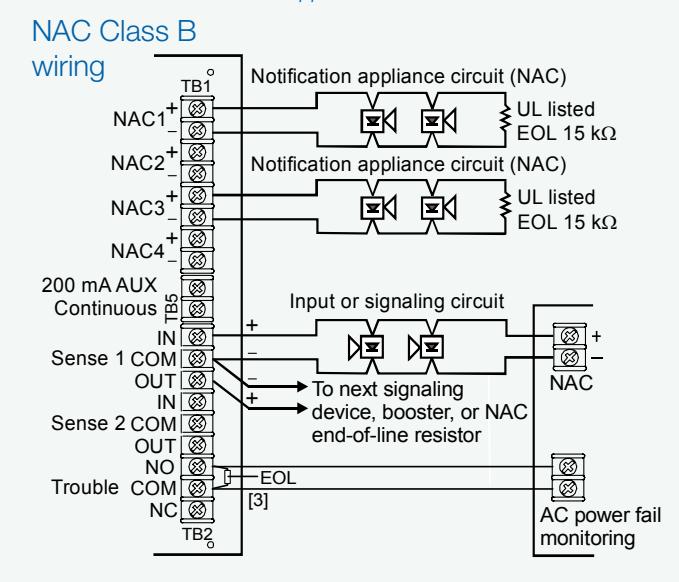
Booster Power Supply
Consult relevant literature for application details.
| Specifications | EBPS6A - 6.5 amp Booster | EBPS10A - 10 amp Booster | |||
|---|---|---|---|---|---|
| AC Line | 120VAC 50/60Hz 390 watts | 120VAC 50/60Hz 580 watts | |||
| Voltage | |||||
| NAC Ratings | 24Vdc nominal | 24Vdc nominal | |||
| 6.5A max total all NACs | 10A max total all NACs | ||||
| Trouble Relay | 2 Amp | s @ 30Vdc | |||
| Auxiliary | Four individually configurable of | utputs can replace NACs 1, 2, 3 or | |||
| Outputs | 4 as auxi | liary outputs. | |||
| 200 mA dedicated auxiliary for use with E-NAC module. | |||||
| Input Current | 6mA @ 24Vdc (from an existing NAC) | ||||
| Current | 70mA (Booster Internal Supervisory) | ||||
| Maximum | 10 Amp Hours (2 of 12V10A) in cabinet | ||||
| Battery Size | up to 24 Amp hours with external battery cabinet (p/n BC-1R) | ||||
| Paige Wire | Twisted nonshielded FPLP #14 AWG - 4719A or #12 AWG - 4725A | ||||
| (THHN or TFN in conduit can be used on NAC) | |||||
| Environmental | Temperature 32° to 120°F (0° to 49°C), | ||||
| Humidity 0 to 93% non condensing @ 32°C | |||||
| NAC Wiring | (4) Class B or (2) Class A | ||||
| Output Signal | Continuous, 3-3-3 temporal, | ||||
| Rates | or follow installed panel's NAC. | ||||
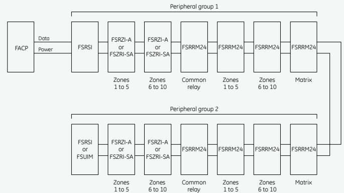
Annunciator Bus
Consult relevant literature for application details.
Notes
- Install only one FSRRM24 configured for common relay operation (jumper installed on JP5) per peripheral group.
- Install zone indicator modules only for zones 6 to 10 on ten-zone control panels.
- For ten-zone control panels, install an F-series remote annunciator in place of the FSRSI and the two zone indicator modules (FSRZI-A or FSRZI-SA).
- If the remote modules require more power than the control panel can provide, use a power-limited and regulated 24 VDC auxiliary/booster power supply that is UL/ ULC Listed for fire protective signaling systems to power all or some of the remote