Edwards Signaling ESL 500N Series Smoke Detector Installation Sheet
Open the original PDF document
View PDF

ESL 500N Series Smoke Detector Installation Sheet
Description
Note: This document is intended for licensed electricians or alarm installers. We cannot provide technical support to unqualified persons. If you have any questions, contact us using the "Contact information" on page 8.
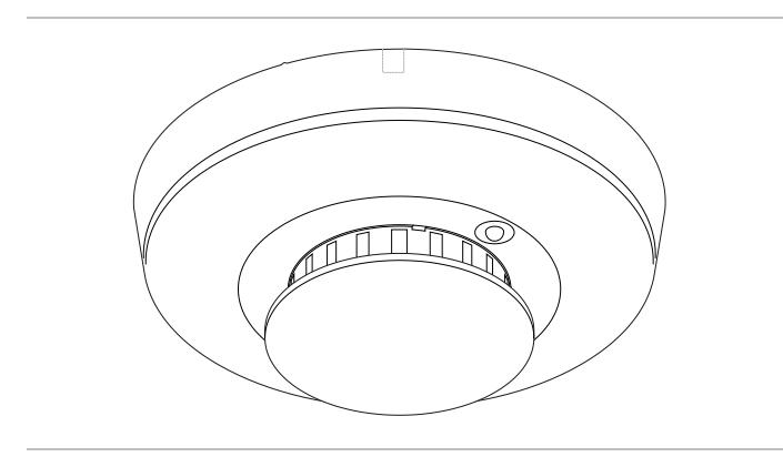
The ESL 500N Series conventional two-wire and four-wire photoelectric smoke detectors have intelligent software and digitally processed sensing capabilities. This intelligence, coupled with the ESL patented optical sensing chamber, means the ESL 500N Series quickly and accurately detects smoke. CleanMe compatible software, self-diagnostics, and dust (drift) compensation are standard in every unit. The ESL 500N Series offers application flexibility with optional auxiliary relays, rate-of-rise/fixed temperature heat sensors, isolated heat sensors and/or 85 dBA temporal-three sounders.
Standard features
All models ship standard with the features described below.
Detector-base lock: Discourages unauthorized removal of the smoke detector by requiring a screwdriver to remove the detector from the base.
Self-diagnostics: Includes automatic sensitivity testing. Once a day and immediately upon first power up, each 500N Series detector performs a full diagnostic test that includes a dynamic test of the sensing chamber and internal electronics. This meets NFPA 72 field sensitivity testing requirements without the need for external meters.
Drift compensation (dust compensation): The detectors automatically adjust sensitivity, up to a maximum of 1.0%/ft., as the detectors become dirty.
Automatic voltage range selection for UL two-wire compatibility: The two-wire 500N Series detectors automatically determine if the detector is connected to a 6/12 V panel or a 12/24 V panel. There are no switches to set.
Additional features
Depending on the model, the smoke detector may also provide the following features.
CleanMe: Enables a CleanMe compatible control panel to receive a warning signal, indicating that the optical chamber needs to be replaced. This feature is available on the 500N Series two-wire detectors only.
The 500N Series two-wire detectors enable the CleanMe function by recognizing voltage polarity at installation. If the + and − terminal connections are reversed, the CleanMe function is enabled. New 500N Series detectors are compatible on the same loop with previous 500 Series detectors if proper wiring is observed. See "Wiring" on page 4.
Integral temporal-three sounder: In the 500N models with sounder, a piezoelectric horn produces an interrupted 85 dBA tone when the detector alarms or when the polarity is reversed. Sounder follows input voltage in reverse polarity.
In order for all sounders to activate when the panel alarms, the panel must reverse the supply voltage polarity to the loop on alarm. If the panel does not implement polarity reversal, an ESL 405 Polarity Reversal Relay Module must be used. (Refer to the installation sheet for the ESL 405 Polarity Reversal Relay Module.)
Auxiliary and end-of-line relays: Auxiliary relays are Form C and operate at 1 A at 30 VDC to allow for the addition of auxiliary notification devices to the smoke loops. Products with an "R" in the suffix signify the auxiliary relay feature.
An end-of-line relay operates as a power supervision relay and is normally energized and will release with the loss of power. Products with an "E" in the suffix signify the end-of-line feature.
Heat sensors: Some models come with rate-of-rise or fixed temperature heat sensors which allow the unit to detect changes in temperature that may signal a fire event. Models with an "XT" in the suffix have a heat sensor included.
Some models are available with an isolated heat sensor. If the unit senses a temperature change it will alert the panel and signal an alarm independent of smoke in the photoelectric chamber. The heat alarm output is on the alarm relay and the smoke detector output is on the auxiliary relay. Models with an "H" in the suffix have an isolated heat sensor which is both rate of-rise and fixed temperature.
Compatibility
Please refer to the ESL Compatibility Index for a complete listing of control panels and proper identifiers. For a copy of the compatibility index, see "Contact information" on page 8. Remember, four-wire smoke detectors do not require a compatibility listing.
Selecting a location
Selecting a suitable location is critical to the operation of smoke detectors. This equipment should be installed in accordance with NFPA 72. Figure 1 shows required and additional locations.
Figure 1: Detector location
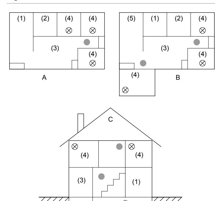
- (1) Dining Room
- (4) Bedroom
- (2) Kitchen
- (5) TV Room
- (3) Living Room
- (6) Basement
- Required smoke detectors
- Additional alarms required for new construction
(6)
Where to locate the required smoke detectors in existing construction. The major threat from fire in a family living unit occurs at night when everyone is asleep. The principal threat to persons in sleeping areas comes from fires in the remainder of the unit. Therefore, a smoke detector is best located between the bedroom areas and the rest of the unit. In units with only one bedroom area on one floor, the smoke detector should be located as shown in Figure 1-A.
In family living units with more than one bedroom area or with more than one floor, more than one smoke detector is required, as shown in Figure 1-B.
In addition to smoke detectors outside of the sleeping areas, the installation of a smoke detector on each additional story of the family living unit, including the basement, is required.
These installations are shown in Figure 1-C. The living area smoke detector should be installed in the living room or near the stairway to the upper level, or in both locations. The basement smoke detector should be installed in close proximity to the stairway leading to the floor above. Where installed on an open-joisted ceiling, the alarm should be placed on the bottom of the joists. The alarm should be positioned relative to the stairway to intercept smoke coming from a fire in the basement before the smoke enters the stairway.
Where to locate the required smoke detectors in new construction. All of the smoke detectors specified for existing construction are required and, in addition, a smoke detector is required in each bedroom.
Are more smoke detectors desirable? The required number of smoke detectors might not provide reliable early warning protection for those areas separated by a door from the areas protected by the required smoke detectors. For this reason, it is recommended that the householder consider the use of additional smoke detectors for those areas for increased protection. The additional areas include the basement, bedrooms, dining room, furnace room, utility room, and hallways not protected by the required smoke detectors. The installation of smoke detectors in kitchens, attics (finished or unfinished), or garages is not normally recommended, as these locations occasionally experience conditions that can result in improper operation.
Note: Regulations pertaining to smoke detector installation vary from state to state. For more information, contact your local fire department or local authority having jurisdiction.
Additional considerations. In addition to NFPA 72, use the following location guidelines to optimize performance and reduce the chance of false alarms from the detector:
- Locate ceiling-mounted smoke detectors in the center of a room or hallway at least 4 in. (10 cm) from any walls or partitions.
- Locate wall-mounted smoke detectors so the top of the alarm is 4 to 12 in. (10 to 31 cm) below the ceiling.
- Do not locate detectors in or near bathrooms or kitchens.
- Locate smoke alarms in a suitable environment with temperature and humidity as defined in "Specifications" on page 8.
- Locate smoke detectors away from air conditioners, heating registers, and any other ventilation source that may interfere with smoke entering the alarm.
- Mount smoke detectors on a firm, permanent surface.
Installing the detector
All wiring must conform to the National Electric Code (NEC) and/or local codes having jurisdiction. Use 12 to 24 AWG (16 to 22 AWG recommended) wire to install the detector.
- 1. If you are using the detector-base lock, remove the detector knockout and break off the tab on the mounting base. See Figure 2.
- 2. Remove the red plastic cover from the detector. The detector is shipped with a cover for protection against construction site dust.
- 3. Run system wiring to the detector location and mount electrical boxes if necessary. The detector fits standard single-gang boxes and 3-1/2 in. and 4 in. round ceiling boxes.
- 4. Line up and attach the mounting base to the electrical box, wall, or ceiling using the screws provided. Use wall anchors if necessary. See Figure 3.
- 5. Strip the system wires and connect them to the appropriate terminals on the detector. See "Wiring" on page 4.
-
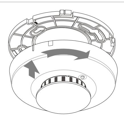
6. Attach the detector to the mounting base as follows:
- a. Line up the raised tab on the side of the detector with the arrow on the mounting base. See Figure 4.
- b. Insert the smoke detector into the base and turn clockwise approximately 15 degrees. It should snap firmly into place.
- 7. Apply power and test the detector. See "Smoke testing" on page 5.
Figure 2: Detector-base lock
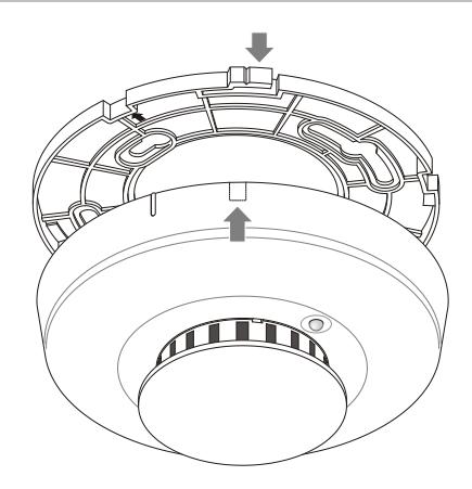
Figure 3: Detector installation
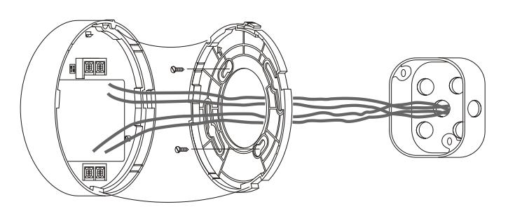
Figure 4: Mounting
Removing the detector
To remove the detector from the mounting base: Grasp the detector and turn it counterclockwise approximately 15 degrees. The detector should snap off of the mounting base.
To remove the detector from the mounting base when the detector-base lock is used: Insert a small screwdriver into the locking tab slot on the side of the base and press in while simultaneously turning the detector counterclockwise 15 degrees. See Figure 5.
Figure 5: Unlocking the detector
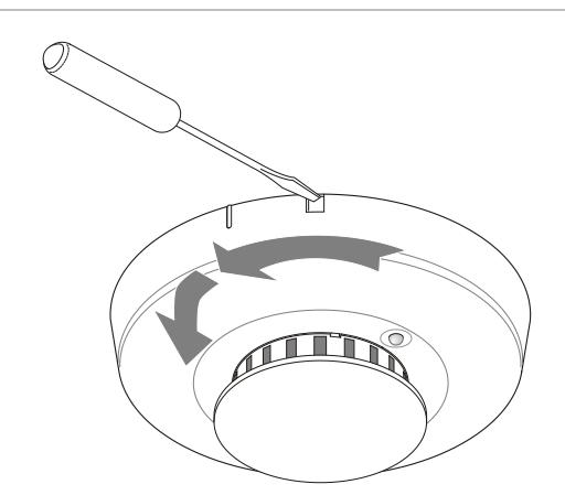
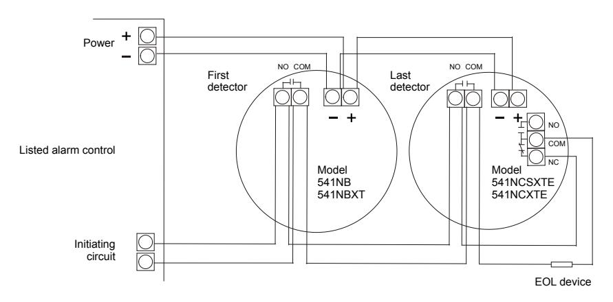
Figure 6: 500N Series two-wire wiring
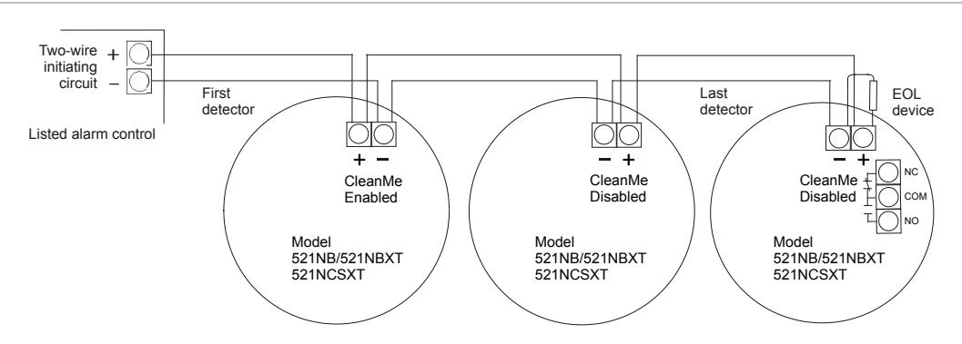
Caution: Risk of system failure. The system may not operate if the detector is not connected to the control unit initiating device circuit as specified in the detector or control unit literature.
Note: The 500N Series two-wire detectors are polarity sensitive.
Note: CleanMe is enabled by wiring units in reverse polarity.
Figure 7: 500N Series four-wire wiring
Note: The 500N Series four-wire detectors are not CleanMe compatible.
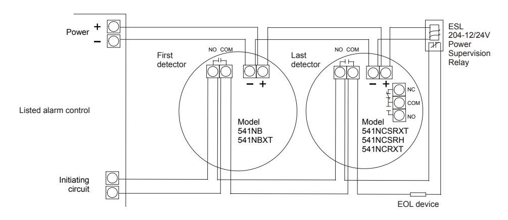
Figure 8: 500N series four-wire E model wiring
Note: The 500N Series four-wire detectors are not CleanMe compatible.
Understanding the LED
The LED on the detector indicates the status of the detector as follows.
- Flashing every 9 seconds = Normal operation
- On = Detects smoke, sending an alarm
- Off or flashing once every 1.5 seconds = Trouble or maintenance is required. Test the detector. See "Sensitivity testing" below.
Smoke testing
Smoke detectors should be tested in place annually using one of the following methods:
- Use Smoke! In A Can (P/N SM-200), a canned aerosol simulated smoke, and follow the directions on the can.
- Hold a smoldering punk or cotton wick close to the unit and gently direct the smoke into the detector for 20 seconds or until an alarm is indicated.
Be sure to extinguish the smoke source after testing!
The detector LED should stay on and an alarm should be indicated at the control panel. Use the system reset switch to reset the detector.
Sensitivity testing
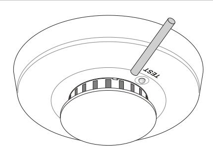
The detector provides a sensitivity test that allows you to check the detector sensitivity using a test magnet and the LED indicator on the detector as follows:
- 1. Hold the test magnet up to the raised TEST letters on the top of the detector for 2 seconds. See Figure 9. Once the test starts, the alarm LED flashes one to nine times.
- 2. Count the number of times the LED flashes and use the following table to determine the status of the detector sensitivity and what action to take, if any.
| Flashes | Indication | Action |
|---|---|---|
| 0 to 1 |
Unserviceable
hardware fault |
Reset and rerun the sensitivity test. If
the error persists, replace the unit. |
| 2 to 3 |
Unit is becoming
insensitive |
Clean and reset the unit. Rerun the
sensitivity test. If the error persists, replace the unit. |
| 4 to 7 |
Unit is within normal
sensitivity range |
N/A |
| 8 to 9 |
Unit is becoming
too sensitive |
Verify that the optical chamber is
snapped down securely. Clean the unit. |
After the test:
- If the sensitivity is within limits and all other tests pass, the detector goes into alarm and must be reset from the control panel.
- If the sensitivity is not within limits or an unserviceable hardware fault has been detected, the detector LED flashes every 1.5 seconds until the detector is serviced.
Figure 9: Testing the detector
Cleaning the detector
Clean the detector cover with a dry or damp (water) cloth as needed to keep it free from dust and dirt.
When necessary, clean the detector interior and replace the optical chamber as follows:
- 1. Disconnect the alarm notification appliances, service release devices, and extinguishing systems.
- 2. Slide a flat-blade screwdriver into the slot on the detector cap and gently push the handle down to pry the cap up and off. See Figure 10.
- 3. Press in on the sides of the optical chamber and pull it up and away from the detector and discard. See Figure 11.
- 4. Use a vacuum to remove dust and dirt from the optical chamber base.
- 5. Line the new optical chamber up with the optical chamber base and snap it down into place.
-
6. Replace the detector cap as follows:
- a. Line the tabs on the cap with the slots on the detector.
- b. Insert the cap into the smoke detector and turn clockwise approximately 15 degrees. It should snap firmly into place.
- 7. Test the detector sensitivity (See "Sensitivity testing" above).
- 8. Reconnect all alarm notification appliances, service release devices and extinguishing systems.
Note: The control panel alarm and all auxiliary functions should be verified for a complete test of the system.
Figure 10: Removing the detector cap
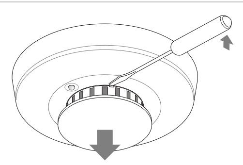
Figure 11: Removing the optical chamber
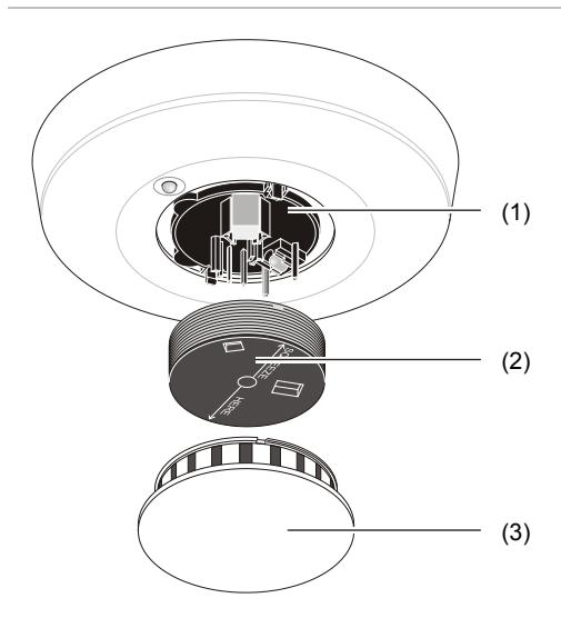
- (1) Optical chamber base
- (2) Optical chamber
- (3) Detector cap
Maintenance
These smoke detectors are designed for easy field service and maintenance. When installed and used properly, they require minimal maintenance.
The smoke detector should be tested monthly. See "Sensitivity testing" and "Smoke testing" on page 5.
Fire prevention and escape
The purpose of an early warning smoke detector is to detect the presence of fire in its early stages and sound an alarm giving the occupants time to exit the premises safely.
Avoid fire hazards
No detection device can protect life in all situations. Therefore, safeguards should be taken to avoid potentially dangerous situations as follows:
- Do not smoke in bed.
- Do not leave children home alone.
- Never clean with flammable liquids such as gasoline.
- Properly store materials. Use general good housekeeping techniques to keep your home neat and tidy. A cluttered basement, attic, or other storage area invites fire.
- Use combustible materials and electrical appliances carefully and only for their intended uses.
- Do not overload electrical outlets.
- Do not store explosive and/or fast burning materials in your home.
- Even after proper precautions have been taken, fires can start. Be prepared.
In case of fire
In the event of a fire, do the following:
- Leave immediately. Don't stop to pack or search for valuables.
- In heavy smoke, hold your breath and stay low, crawl if necessary. The clearest air is usually near the floor.
- If you have to go through a closed door, carefully feel the door and doorknob to see if undue heat is present. If they seem cool, brace your foot against the bottom of the door with your hip against the door and one hand against the top edge. Open it slightly. If you feel a rush of hot air, slam the door quickly and latch it. Unvented fire tends to build up considerable pressure. Be sure all members of the household realize and understand this danger.
- Use your neighbor's phone or a street fire alarm box to call the fire department. The job of extinguishing the fire should be left to the professionals.
Be prepared
Practice the following steps to prepare you and your family in the event of a fire:
- Perform fire drills regularly. Use them to assure recognition of an alarm signal.
- Draw a floor plan and show two exits from each room. It is important that children be instructed carefully, because they tend to hide in times of crisis.
- Establish one meeting place outside the home. Insist that everyone meet there during an alarm. This will eliminate the tragedy of someone reentering the house for a missing member who is actually safe.
- If you have children or physically challenged people residing in your household, use window decals to help emergency personnel identify the sleeping quarters of these individuals.
Limitations of smoke detectors
WARNING: Risk of personal injury or death. Smoke detectors cannot provide warnings for fires resulting from explosions, smoking in bed or other furniture, ignition of flammable liquids, vapors, and gases, or children playing with matches or lighters. Failure to properly install, test, and maintain a smoke detector system may cause it to fail resulting in loss of life or property.
Smoke detectors are very reliable, but may not work under all conditions. No fire alarm provides total protection of life or property. Smoke detectors are not a substitute for life insurance.
Smoke detectors require a source of power to work. This smoke detector will not operate and the alarm will not sound if the detector is not installed properly.
Smoke detectors may not be heard. A sound sleeper or someone who has taken drugs or alcohol may not awaken if the detector is installed outside a bedroom. Closed or partially closed doors and distance can block sound. This detector is not designed for the hearing impaired.
Smoke detectors may not always activate and provide warning early enough. Smoke detectors only activate when enough smoke reaches the detector. If a fire starts in a chimney, wall, roof, on the other side of closed doors, or on a different level of the property, enough smoke may not reach the detector for it to alarm.
Smoke detectors are a significant help in reducing loss, injury, and even death. However, no matter how good a detection device is, nothing works perfectly under every circumstance and we must warn you that you cannot expect a smoke detector to ensure that you will never suffer any damage or injury.
Current studies have shown smoke detectors may not awaken all sleeping individuals. It is the responsibility of individuals in the household that are capable of assisting others to provide assistance to those who may not be awakened by the alarm sound, or to those who may be incapable of safely evacuating the area unassisted.
Model numbers
Figure 12: Model number codes

| B | 6 to 33 V operation |
| C | 8.5 to 33 V operation |
| E | End-of-line relay |
| H | Isolated rate-of-rise and fixed temp. sensors |
| N | New style |
| R | Auxiliary relay |
| S | 85 dBA sounder |
| XT | Multiple criteria algorithm, rate-of-rise and fixed temp. sensors |
Product ordering
| Model | Description |
Alarm
current (mA) |
Reverse
polarity (mA) |
|---|---|---|---|
| 521NCRXT | Two-wire, photoelectric, 8.5 to 33 VDC, fixed temperature and rate-of-rise heat, aux. relay, S11A | 25 | – |
| 521NCSXT |
Two-wire, photoelectric, 8.5 to 33 VDC, fixed temperature and rate-of-rise heat, temporal-three
sounder |
13 | |
| 541NB | Four-wire, photoelectric, 6 to 33 VDC | 20 | – |
| 541NBXT | Four-wire, photoelectric, 6 to 33 VDC, fixed temperature and rate-of-rise heat | 20 | – |
| 541NCSRXT |
Four-wire, photoelectric, 8.5 to 33 VDC, fixed temperature and rate-of-rise heat, aux. relay,
temporal-three sounder |
35 | 13 |
| 541NCSXTE |
Four-wire, photoelectric, 8.5 to 33 VDC, fixed temperature and rate-of-rise heat, built-in end-of
line relay, temporal-three sounder |
45 | 28 |
| 541NCSRH |
Four-wire, photoelectric, 8.5 to 33 VDC, isolated fixed temperature and rate-of-rise heat, aux.
relay, temporal-three sounder, nonlatching LED with automatic reset |
13 | |
| 541NCRXT | Four-wire, photoelectric, 8.5 to 33 VDC, fixed temperature and rate-of-rise heat, aux. relay | 25 | – |
| 541NCXTE |
Four-wire, photoelectric, 8.5 to 33 VDC, fixed temperature and rate-of-rise heat, built-in end-of
line relay |
25 | – |
| 541NCSXT |
Four-wire, photoelectric, 8.5 to 33 VDC, fixed temperature and rate-of-rise heat, temporal-three
sounder |
30 | 13 |
Specifications
|
For standard 6/12 V operation (6 to 20 VDC),
polarity sensitive |
|
|
For standard 12/24 V operation (8.5 to
33 VDC), polarity sensitive |
|
| 10% (Vp-p) | |
| 70 µA | |
|
Up to 60 mA maximum if not limited by
control panel |
|
| 1 A at 30 VDC; Form C | |
| 500 mA at 36 VDC (resistive) | |
| 2.0% +1.08 −1.02 | |
| 32 to 100°F (0 to 37°C) | |
| 0 to 95% noncondensing | |
| 20 V/m minimum; 0 to 1,000 MHz | |
| White head and base | |
| 12 to 24 AWG (16 to 22 AWG recommended) | |
|
Fits standard single-gang and 3-1/2 in. and
4 in. round ceiling electrical boxes |
|
| 10 detectors per carton | |
|
15°F/min and >105°F (8.3°C/min and
>40.6°C) 135°F (57.2°C) |
|
| S09A, S10A, S11A | |
| 1.0%/ft. max. | |
|
5.5 in. (14.0 cm) diameter; 2 in. (5.0 cm)
deep |
|
|
5.25 in. (13.3 cm) diameter; 0.3 in. (0.8 cm)
deep |
|
Regulatory information
| Listings | CSFM,MEA |
|---|---|
| State of Maryland | |
| UL 268 and CAN/ULC-S531 |
Contact information
For contact information, see www.interlogix.com.