Edwards Signaling EC-50R-100R Installation Instruction
Open the original PDF document
View PDFReflective Optical Beam Smoke Detector User Guide
1. Installation
- IMPORTANT NOTE: The infrared beam path MUST be kept clear of obstructions at all times! Failure to comply may result in the system initiating a Fire or Fault signal
- Detector installation must comply with local regulations. UL listed products must comply with NFPA72
- Ensure clear line of sight between Detector and Reflector it is recommended at least 0.5m radius of clear space be maintained around the centre of the beam path
- Mount securely to solid structural surfaces
- Position beam as high as possible, but with a minimum distance of 0.5m from Detector to ceiling. For installations complying with UL268/NFPA72, the maximum distance of Detector and Reflector from the ceiling must be 10% of the distance between floor and ceiling
- Mount Detector and Reflector directly opposite each other
- Do NOT position Detector where personnel or objects can enter beam path
- Do NOT position two Detectors facing each other
- Do NOT install the Detector or Reflector in environments where condensation or icing are likely to occur
- For ranges between 5m and 50m, use a 50m Detector with 1 Reflector.
- For ranges between 50m and 100m, use a 100m Detector with 4 Reflectors.
2. User Configuration Settings
Access to the configuration settings is through the back plate of the Detector Head. Factory default configuration settings are marked .
| Dip switch | |||||
|---|---|---|---|---|---|
| Function | 1 | 2 | 3 | 4 | |
| Auto Reset Fire Relay (5 seconds) | ON | | |||
| Latching Fire Relay | |||||
| Fire Relay Enable, On Compensation Limit | OFF | | |||
| Fire Relay Disable, On Compensation Limit | ON | ||||
| 50% Threshold | OFF | OFF | |||
| 35% Threshold | OFF | ON | | ||
| 25% Threshold | ON | OFF | |||
| 12% Threshold (Use for extreme sensitivity | ON | ON | |||
| requirements) | |||||
- The Detector is set to Latching Mode or Auto Reset Mode using DIP Switch 1. If in Auto Reset Mode, the Detector will automatically recover from a Fire state when the fire condition has been removed. If in Latching Mode, it will remain in Fire state until either the Detector is placed in Prism Targeting Mode or Alignment Mode, then back to Operating Mode, OR power is removed from the Detector for 10 seconds.
- Fire Relay Enable/Disable on Compensation Limit is set with DIP Switch 2. This mode selects whether Fire activation is still enabled during an AGC Compensation Fault.
- The Sensitivity of the Detector is set using DIP Switches 3 and 4.
- Do not use the 12% or 25% Alarm threshold for UL listed 100m Detectors, as this will not conform to UL268
3. Wiring Diagram
For connection of a single conventional Detector to a zone:
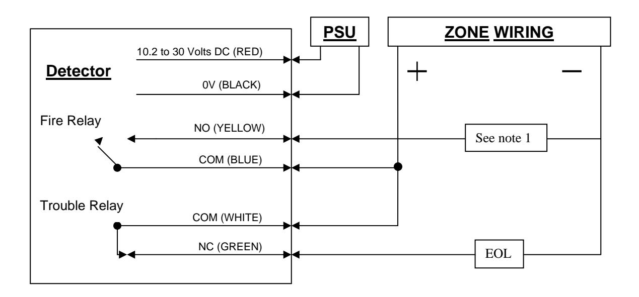
Note 1 – This component is the Fire Resistor, and its value is specified by the Fire Control Panel Manufacturer. For US installations it is typically a short circuit.
EOL – End of Line component – supplied by the Fire Control Panel manufacturer
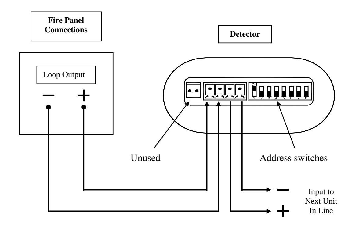
For Analogue Addressable variants:
For connection of multiple conventional Detectors to a zone:
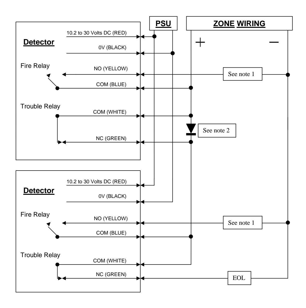
Note 1 – This component is the Fire Resistor, and its value is specified by the Fire Control Panel Manufacturer. For US installations it is typically a short circuit.
Note2 – Schottky Diode (60Volt, 1 Amp typical; must be UL listed for installations meeting NFPA72)
EOL – End of Line component – supplied by the Fire Control Panel manufacturer
4. Prism Targeting Mode
Apply power to the Detector. After 5 seconds the RED LED will flash once to indicate that the model is a 50m detector, or twice to indicate a 100m detector.
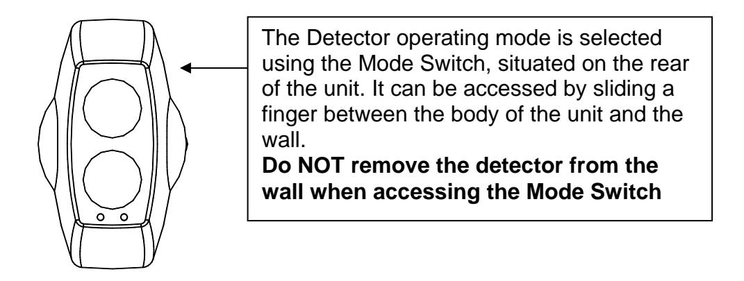
Select Prism Targeting Mode by moving the Mode Switch to the upper position.
Find the prism by adjusting the horizontal and vertical thumbwheels until the AMBER LED is continuously ON. The AMBER LED will be OFF when no signal is being received, then will flash at an incrementing rate to determine the target position. The faster the flash the nearer you are to the target (prism).
At this point it is essential to test that the prism and not another surface is reflecting the beam. Cover the prism with a non-reflective material and confirm that the AMBER LED turns OFF.
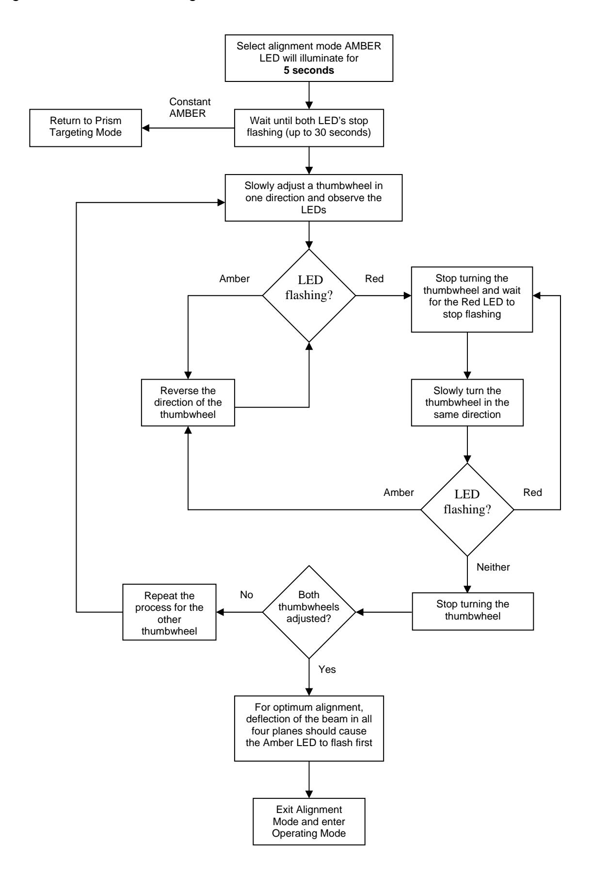
5. Alignment Mode
Select Alignment Mode by moving Mode Switch to the middle position. The Detector will automatically adjust its infrared beam power and receiver sensitivity to give an optimum receiver signal strength. The progress of this is indicated by the LEDs on the front of the detector:
- CONTINUOUSLY AMBER : The Detector is not receiving a signal. Go back to prism targeting mode.
- FLASHING RED : The Detector is receiving too much signal and is attempting to reduce the infrared power output to compensate . Wait at this point until the LED is OFF , this may take up to 20 seconds depending on the distance between Detector and Prism, the shorter the distance the longer the time.
- FLASHING AMBER : The Detector is receiving a weak signal and is attempting to increase the infrared power output.
- OFF : The Detector has optimised the infrared power and receiver gain for the current orientation of the Detector and Prism. This does not mean that the Detector to Prism alignment is at its optimum , i.e. if the power is too high, a misaligned Detector may be receiving a fringe reflection from another object.
- FLICKERING RED/AMBER : This state can occur sometimes. It means that the infrared power is stepping through the optimum setting.
Continue to flow diagram for procedure.
6. Operating Mode
Select Operating Mode by moving the Mode Switch to its lower position.
On exiting alignment mode the Detector will perform an internal calibration check. Do not block the beam whilst this internal calibration takes place. The Amber LED will flash once a second, for up to sixty seconds, and then go out. If this fails, which would be due to bad alignment or either electrical/optical noise, the detector will indicate a Fault condition. In this case the alignment procedure must be repeated.
If the internal calibration check completes satisfactory, the Detector will now be in normal operating mode.
7. System Testing
After successful installation and alignment the System will require testing for both alarm and fault conditions.
Fault (Trouble) Test
Using a non-reflective object, quickly cover the entire prism(s). The Detector will indicate a fault within 10 seconds by activating the FAULT LED and operating the Fault Relay. The fault condition will automatically reset when the obstruction is removed.
Alarm (Smoke) Test
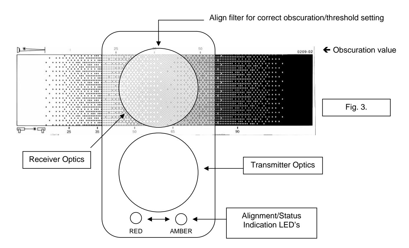
Taking note of the threshold selected during installation, select obscuration mark on filter to correspond with the Detector Alarm threshold (see fig. 3).
Place the filter over the receiver optics (Top of Detector Head opposite end to the status indication LED's) at the correct obscuration value determined by the threshold selected. For example, if a threshold of 35% has been selected position the filter just past the 35% obscuration value on the filter (see fig 3.). Take care not to cover the transmitter optics.
8. Servicing and Maintenance
During Operating Mode, the following states will be indicated:
- Normal (no Fault or Fire) Amber LED will flash every 10 seconds (EN approved model) or not flash at all (UL approved model)
- Fire/Alarm Red LED will be on continuously, and Fire Relay will close
- Fault Amber LED on continuously, and Fault Relay will open
- Compensation Fault Amber LED flashes every 2 seconds
A Compensation Fault will occur when the Detector can no longer compensate for signal loss due to dust/dirt build-up on the lenses and/or Reflector. A Compensation Fault can be cleared by cleaning the Reflector and Detector lenses using a dry lint-free cloth, and then realigning the beam. Compensation Faults can be avoided by periodic cleaning of the Reflector and Detector before compensation limit is reached.
9. Technical Data
| | Operating Range (50 metre Detector) | 5 to 50 metres |
|---|---|---|
Operating Range (100 metre Detector) 50 to 100 metres
Supply Voltage limits 10.2Vdc to 30Vdc
Quiescent Current (no LED's illuminated) <4mA
Alarm/Fault Current <15 mA
Power Down Reset Time 10 seconds
Operating Temperature (EN) -10C to 55C
Operating Temperature (UL) 32F to 100F
Relative Humidity 93% (non-condensing)
Tolerance to Beam Misalignment at 35% Detector 1.0, Prism 5.0
Fire Alarm Thresholds 2.50dB (25%), 3.74dB (35%), 6.02dB (50%)
Optical Wavelength 880nm
Head Maximum Size Width 130mm, Height 210mm, Depth 120mm
Weight 770 gms
IP rating IP50