Edwards Signaling E-RLY Modules Connected to MR Series Multivoltage Control Relays Technical Bulletin
Open the original PDF document
View PDF

Field Notes Bulletin
TECHNICAL SUPPORT FNN 10021E • ISS 07SEP10
eFSA: E-RLY Modules Connected to MR Series Multivoltage Control Relays
Introduction
This bulletin informs you of an issue with E-RLY modules connected to MR Series Multivoltage Control Relays, and tells you how to resolve it.
Issue
Due to a change by Air Products, the 120 VAC input circuits on MR-100, -200, and -800 Series Multivoltage Control Relays present a capacitive load to the E-RLY, instead of a resistive load. As a result, the E-RLY contacts do not reliably change state when activated, even though the red "Active" LED turns on. E-RLY activation is not affected when using the 24 V input control voltages on the control relay.
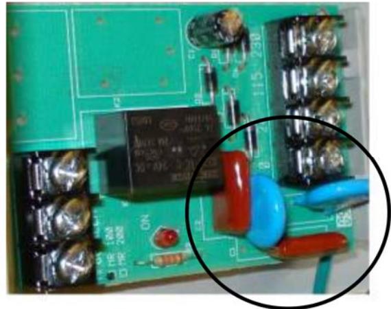
Figure 1 on page 2 shows the difference between new board layouts (with capacitors) and old board layouts (without capacitors). We are attempting to find out when Air Products changed their product design. Until then, use Figure 1 on page 2 to determine if this change affects you.
Note: Other Signature modules that have contacts rated for 120 VAC at 500 mA, Pilot Duty (inductive or resistive loads only) may also be affected. Typically, the E-RLY module is used in this type of application. In addition, other control relays such as the PAM-1 may be affected.


Solution
If you are using E-RLY modules to transfer 120 V in order to energize MR Series Multivoltage Control Relays, determine if the MR Series Multivoltage Control Relays have capacitors as shown in Figure 1. If they do, we recommend that you do one of the following:
- Eliminate the MR Series Multivoltage Control Relay by controlling the 120 V directly with the E-RLY (provided the load meets the contact ratings for the E-RLY).
- Use 24 VDC from the nearest existing power supply to energize the MR Series Multivoltage Control Relay.
- Use 24 VAC to energize the MR Series Multivoltage Control Relay. This requires the addition of a 24 VAC power source that is UL/ULC Listed for fire protective signaling services. Note: If you use this option, the relay will not be energized in the event of a power failure.
At installations where it isn't practical to install a 24 VDC power supply or run new wiring from an existing power source, we recommended using a Model 592 Low Voltage Class 2 Signaling Transformer from Edwards Signaling to step the 120 VAC down to 24 VAC. See Figure 2 and Figure 3 on page 3.
The Model 592 transformer mounts directly onto an MR-101 enclosure. If you need to mount the Model 592 transformer into a two-gang electrical box, you need to use a Model 593 mounting bracket. Both the transformer and the mounting bracket may be purchased through Customer Service.
For more information on the Model 592 Low Voltage Class 2 Signaling Transformer, visit www.edwards-signals.com.
Figure 2: Model 592 transformer mounted onto an MR-101
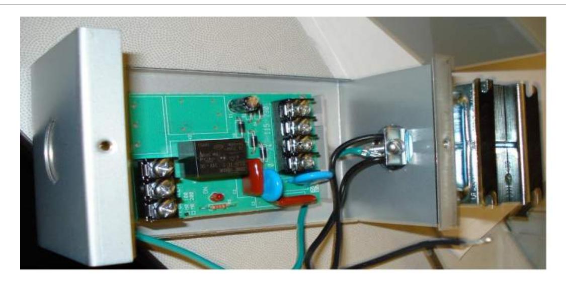
Figure 3: 24 VAC wiring diagram
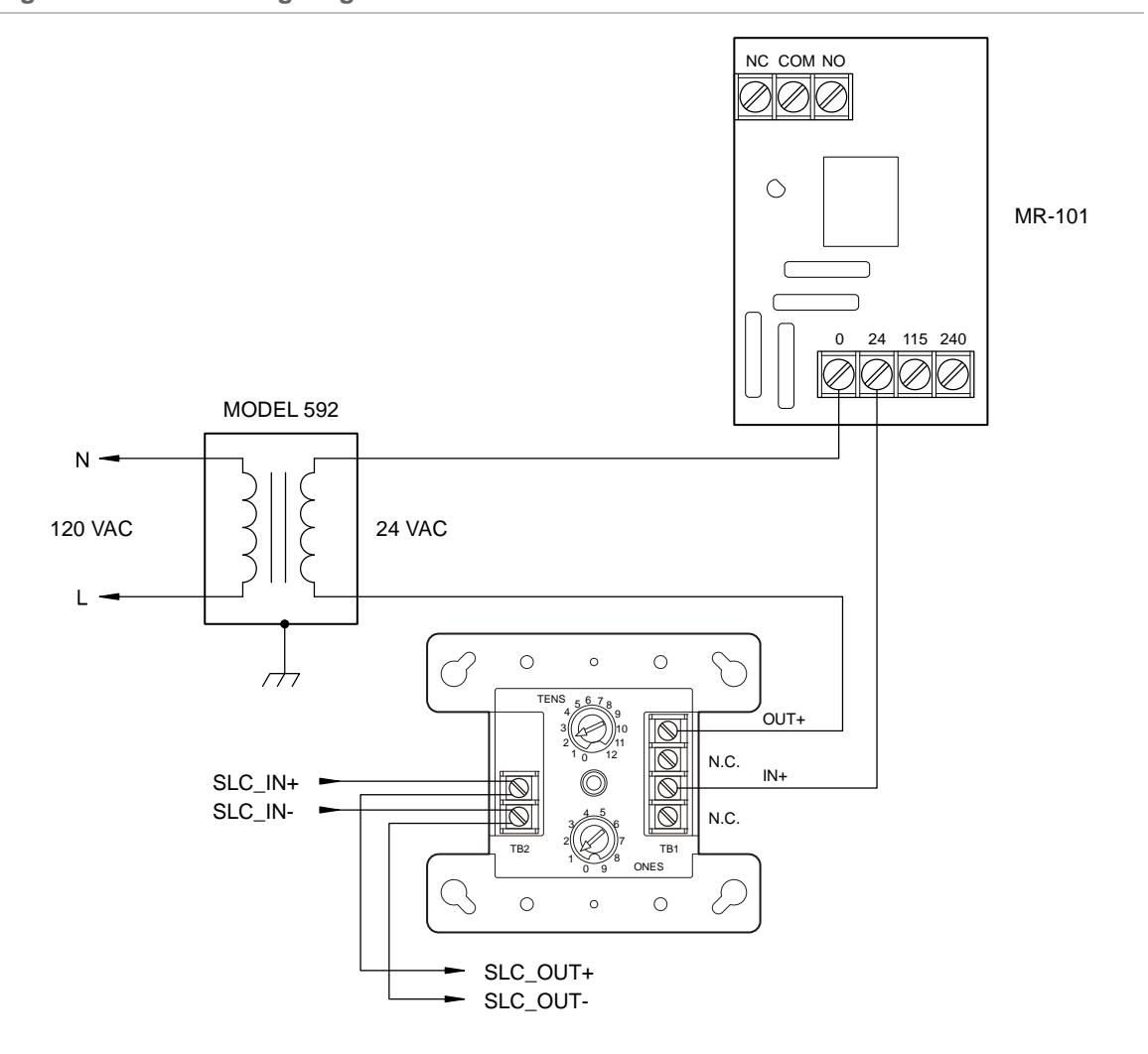
Note: The MR Series relay shown in Figure 3 is energized. Activating the E-RLY module in this configuration de-energizes the MR Series relay.
For loads with unknown electrical characteristics, or 120 VAC current exceeding 500 ma, we recommend using 24 VAC as the input control voltage.
If you have further questions regarding E-RLY applications, please contact Technical Support at the number listed below.
Contacting support
UTC Fire & Security 8985 Town Center Parkway Bradenton, FL 34202
T (800) 336-4206 F (860) 793-5188 E signaling.techsupport@fs.utc.com