Edwards Signaling Data Sheets Genesis Ceiling Speaker Strobes
Open the original PDF document
View PDF

Field Configurable Ceiling Speaker -strobes
Genesis Series

Overview
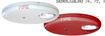
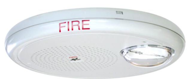
Genesis life safety ceiling speaker-strobes are small, compact, and attractive audible-visible emergency signaling devices. Protruding no more than 1.6" (41 mm) from the ceiling, Genesis speakerstrobes blend with any decor.
Life safety appliances feature textured housings in architecturally neutral white or eye-catching life safety red.
Thanks to patented breakthrough technology, Edwards Genesis strobes do not require bulky specular reflectors and lenses. Instead, an exclusive cavity design conditions light to produce a highly controlled distribution pattern. FullLight strobe technology produces a smooth light distribution pattern without the spikes and voids characteristic of specular reflectors. This ensures the entire coverage area receives consistent illumination from the strobe flash.
Depending on the model, Genesis clear-lens speaker-strobes feature 15 to 95, or 95 to 177 candela output (see ordering information), which is selectable with a conveniently-located switch. The candela output setting remains clearly visible even after final installation, yet it is locked in place to prevent unauthorized movement after installation.
Standard Features
• Field configurable – no need to remove the device!
- Select ¼, ½, 1, or 2 watt operation
- 15/30/75/95 cd and 95/115/150/177 cd clear strobe lens models available
- Switch settings remain visible even after the unit is installed
• Unique low-profile design
- 30 per cent slimmer profile than comparable signals
- Available with white or red housings
• Unparalleled performance
- loud 90 dBA output ensures clear, crisp audio
- Precision timing electronics meet tough synchronizing standards for strobes when used with compatible modules
- 25 VRMS and 70 VRMS models available, all supplied with a DC blocking capacitor for audio circuit supervision
• Easy to install
- Fits all standard 4" square electrical boxes with plenty of room for extra wire – no extension ring or trim plate needed
- #18 #12 AWG terminals ideal for long runs, existing wiring
• Approved for public and private mode applications
- UL 1971-listed as signaling devices for the hearing impaired
- UL 1638-listed as protective visual signaling appliances
- UL 1480-listed as life safety speaker
- UL/ULC listed for ceiling or wall use
Strobe Application
Genesis strobes are UL 1971 or 1638 listed for indoor use. Prevailing codes require strobes to be used where ambient noise conditions exceed specified levels, where occupants use hearing protection, and in areas of public accommodation. Consult with your Authority Having Jurisdiction for details.
All Genesis strobes exceed UL synchronization requirements (within 10 milliseconds over a two-hour period) when used with a synchronization source. Synchronization for multiple strobe lights in a single field of view is required.
Speaker Application
The suggested sound pressure level for each signaling zone used with alert or alarm signals is a minimum of 15 dB above the average ambient sound level or 5 dB above the maximum sound level having a duration of at least 60 seconds, whichever is greater. This is measured 5 feet (1.5 m) above the floor.
Doubling the distance from the signal to the ear will theoretically cause a 6 dB reduction in the received sound pressure level. The actual effect depends on the acoustic properties of materials in the space. Doubling the power output of a device (e.g.: a speaker from 1 W to 2 W) will increase the sound pressure level by 3 dBA. A 3 dBA difference represents a barely noticeable change in volume.
Combination audible/visual signals must be installed in accordance with guidelines established for strobes.
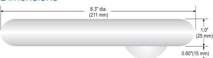
Dimensions
Sound Level Output
| Wattage | 25V | 25V | 70V | 70V |
|---|---|---|---|---|
| UL Rated* | Typical | UL Rated* | Typical | |
| ¼ W | 80 dBA | 80.7 dBA | 80 dBA | 81.1 dBA |
| ½ W | 84 dBA | 83.7 dBA | 84 dBA | 83.5 dBA |
| 1 W | 87 dBA | 87 .1 dBA | 87 dBA | 87.2 dBA |
| 2 W | 90 dBA | 90.1 dBA | 91 dBA | 90.2 dBA |
*Sound level output notes: dBA = Decibels, A-weighted. UL1480: Sound level output at 10 ft (3.05 m) measured in a reverberant room using 400 to 4,000 Hz band limited pink noise. ULC-S541: Meets or exceeds 85 dBA in an anechoic chamber at 10 ft (3.05 m). Directional characteristics: Within 6 dB of on-axis sound level when measured 90° off-axis (horizontal).
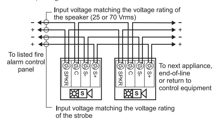
Wiring
Field wiring terminals accommodate #18 to #12 AWG (0.75 mm² to 2.5 mm²) wiring.
Installation and Mounting
All models are intended for indoor ceiling or wall applications only. Speaker-strobes are mounted to a flush North-American 4" square electrical box, 21 /8" (54 mm) deep.
Genesis ceiling speakerstrobes simply unlatch and hinge down to open. This gains access to mounting screws and the selectable candela wattage tap switches. The shallow depth of Genesis devices leaves ample room behind the signal for extra wiring. Once installed with the cover in place, no mounting screws are visible.
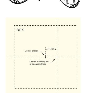
Installation Note:
When installed, these devices are not centered on the electrical box. Make
sure boxes are mounted to compensate for this difference. Use the mounting template provided with installation sheet 3100614.
Field Configuration
Genesis ceiling speakerstrobes may be set for ¼, ½, 1, or 2 watt operation. Depending on the model, Genesis ceiling speaker-strobes have multi-candela output (see ordering information).
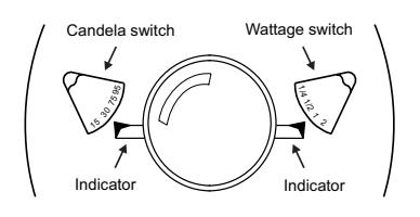
Output settings are changed by simply opening the device and sliding the switches to the desired settings. The speaker-strobe does not have to be removed to change the output settings. The settings remain visible through small windows on the front of the device after the cover is closed.
Typical Sound Output (dBA)
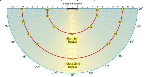
Measured at 2 watts setting in anechoic chamber
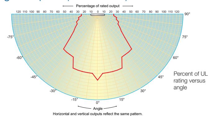
Light output - (effective cd)
Current Draw
| UL Nameplate Rating | els) | UL Nameplate Rating (high cd output mod | ||||||
|---|---|---|---|---|---|---|---|---|
|
See
note 1 |
"15" or
"D" |
"30" or
"C" |
"75" or "B" "95" or "A" |
"95" or
"D" |
"115" or
"C" |
"150" or
"B" |
"177" or
"A" |
|
| RMS | RMS | RMS | RMS | RMS | RMS | RMS | RMS | |
| 16 Vdc | 109 | 151 | 281 | 318 | 330 | 392 | 502 | 565 |
| 16 Vfwr | 131 | 194 | 379 | 437 | 432 | 518 | 643 | 693 |
| 16 Vfwr | 131 | 194 | 379 | 437 | 432 | 518 | 643 | 693 |
|---|---|---|---|---|---|---|---|---|
| Typical Current | Typical Current (high cd output models) | |||||||
|
See
note 1 |
"15" or
"D" |
"30" or
"C" |
"75" or "B" "95" or "A" | 95 cd | 115 cd | 150 cd | 177 cd | |
| RMS | RMS | RMS | RMS | RMS | RMS | RMS | RMS | |
| 16 Vdc | 94 | 140 | 273 | 325 | 333 | 392 | 499 | 551 |
|
See
note 1 |
"15" or
"D" |
"30" or
"C" |
"75" or "B" "95" or "A" | 95 cd | 115 cd | 150 cd | 177 cd | |
|---|---|---|---|---|---|---|---|---|
| RMS | RMS | RMS | RMS | RMS | RMS | RMS | RMS | |
| 16 Vdc | 94 | 140 | 273 | 325 | 333 | 392 | 499 | 551 |
| 20 Vdc | 74 | 108 | 205 | 244 | 259 | 303 | 378 | 429 |
| 24 Vdc | 63 | 90 | 168 | 194 | 212 | 245 | 306 | 342 |
| 33 Vdc | 48 | 70 | 124 | 139 | 155 | 180 | 211 | 236 |
| 16 Vfwr | 126 | 187 | 368 | 403 | 484 | 570 | 673 | 724 |
| 20 Vfwr | 108 | 156 | 281 | 333 | 380 | 438 | 537 | 604 |
| 24 Vfwr | 97 | 139 | 240 | 270 | 318 | 361 | 434 | 484 |
| 33 Vfwr | 89 | 119 | 197 | 214 | 245 | 269 | 308 | 338 |
els)
|
"15" or
"D" |
"30" or
"C" |
"75" or "B" "95" or "A" |
"95" or
"D" |
"115" or
"C" |
"150" or
"B" |
"177" or
"A" |
|
|---|---|---|---|---|---|---|---|
| RMS | RMS | RMS | RMS | RMS | RMS | RMS | RMS |
| 109 | 151 | 281 | 318 | 330 | 392 | 502 | 565 |
| 131 | 194 | 379 | 437 | 432 | 518 | 643 | 693 |
| Typical Current | Typical Current (high cd output models) | ||||||||
|---|---|---|---|---|---|---|---|---|---|
|
"15" or
"D" |
"30" or
"C" |
"75" or "B" "95" or "A" | 95 cd | 115 cd | 150 cd | 177 cd | |||
| RMS | RMS | RMS | RMS | RMS | RMS | RMS | RMS | ||
| 94 | 140 | 273 | 325 | 333 | 392 | 499 | 551 | ||
| 74 | 108 | 205 | 244 | 259 | 303 | 378 | 429 | ||
| 63 | 90 | 168 | 194 | 212 | 245 | 306 | 342 | ||
| 48 | 70 | 124 | 139 | 155 | 180 | 211 | 236 | ||
| 126 | 187 | 368 | 403 | 484 | 570 | 673 | 724 | ||
| 108 | 156 | 281 | 333 | 380 | 438 | 537 | 604 | ||
| 97 | 139 | 240 | 270 | 318 | 361 | 434 | 484 | ||
Notes
- 1. Light output switch settings for UL 1971 listed models are selectable by numeric candela value. ECS/MNS appliances are selectable by A, B, C, or D designations.
- 2. Current values are shown in mA.
Specifications
| Housing |
Textured UV stabilized, color impregnated engineered
plastic. Exceeds 94V-0 UL flammability rating. Red and white models available. |
|---|---|
| Mounting |
Flush mount to North American 4-inch square electrical
box, 2-1/8 (54 mm) inches deep, or 960A-4RF round flush box. No extension ring required. Suitable for indoor wall or ceiling applications. |
|
Wire con
nections |
Screw terminals: polarized inputs for speaker, #18 to #12
AWG (0.75 mm² to 2.5 mm²) wire size |
|
Operating
environment |
Indoor: 32-120° F (0-49° C) ambient temperature; 0-93%
relative humidity. |
|
Agency
listings/ approvals |
Meets ULC-S541, year 2004 UL requirements for
standards UL1638 and UL1971, FM, MEA, CSFM, and complies with UL1480 Fifth Edition. All speaker-strobes comply with ADA Code of Federal Regulation Chapter 28 Part 36 Final Rule. |
| Speaker | |
|
Input/Oper
ating Volts |
25 Vrms (Model EGC-S2VM) or 70 Vrms (Model EGC
S7VM). |
| Strobe | |
|
Strobe out
put rating |
UL 1971, UL 1638, ULC S526: selectable 15/30/75/95
cd (VM models) and 95/115/150/177 cd (VMH models) |
|
Strobe
operating voltage |
EGC-S2VM/-S7VM series speaker-strobes: non-coded,
filtered 16-33 Vdc or unfiltered 16-33 Vdc FWR |
|
Strobe flash
rate |
EGC-S2VM/-S7VM series speaker-strobes: one flash per
second synchronized with optional EG1M Genesis Sig nal Master indefinitely within 10 milliseconds. Temporal setting (private mode only): synchronized to temporal output of Genesis audible signals on same circuit |
|
Synchroni
zation |
Meets or exceeds UL 1971 requirements. Maximum
allowed resistance between any two devices is 20 Ohms. Refer to specifications for the synchronization control module, this strobe, and the control panel to determine allowed wire resistance. |
|
Synchro
nization Sources |
EG1M-RM, EBPS6A, EBPS10A, E-NAC, E-FSC, E-FSA |
| Lens | Optical grade polycarbonate |

Contact us...
Phone: 1-800-336-4206
Web: www.edwardssignaling.com
Edwards Signaling is an EDWARDS brand.
3 Farm Glen Boulevard Farmington, CT 06032
In Canada, contact Chubb Edwards... Email: inquiries@chubbedwards.com Web: <u>www.chubbedwards.com</u>
© 2013 UTC Fire & Security Americas Corporation, Inc. All rights reserved. Specifications subject to change without notice. Edwards is part of UTC Climate, Controls & Security, a unit of United Technologies Corporation.
Ordering Information
| Model |
Hous-
ing |
Mark-
ing |
Lens | Strobe | Speaker | Ship Wt. | ||
|---|---|---|---|---|---|---|---|---|
| Life safety Appliances (c/w running man icon screen printed on housing) | ||||||||
| EGC-S2VM | White | None | Selectable | |||||
| EGCF-S2VM | White | FIRE | 15, 30, 75, or 95 cd | 25 Volt | ||||
| EGC-S2VMH | White | None | Selectable High Output | 25 VOIL | 0.05 # | |||
| EGCF-S2VMH | White | FIRE | 95, 115, 150, or 177 cd | |||||
| EGC-S7VM | White | None | Clear | Calantabla | 2.25 lb. | |||
| EGCF-S7VM | White | FIRE |
Selectable
15, 30, 75, or 95 cd |
(1.0 kg.) | ||||
| EGCFR-S7VM | Red | FIRE | 15, 50, 75, 0f 95 Cd | |||||
| EGC-S7VMH | White | None | 1 | Selectable High Output | ||||
| EGCF-S7VMH | White | FIRE | 1 | 95, 115, 150, or 177 cd | ||||
Accessories
| EG1M-RM | Synchronization Output | 0.2 |
|---|---|---|
| EG IIVI-NIVI | Module (1-gang) | (0.1) |
All speaker-strobes include field-selectable 1/4, 1/2, 1, or 2 watt taps
WARNING: These devices will not operate without electrical power. As fires frequently cause power interruptions, further safeguards such as backup power supplies may be required.
Edwards recommends that these speakerstrobes always be installed in accordance with the latest recognized edition of national and local codes.