Edwards Signaling Data Sheet K85005-0137 – FX Series Intelligent Fire Alarm Systems
Open the original PDF document
View PDF

Technology that saves lives
Intelligent Fire Alarm Systems
FX-64, FX-1000


Overview
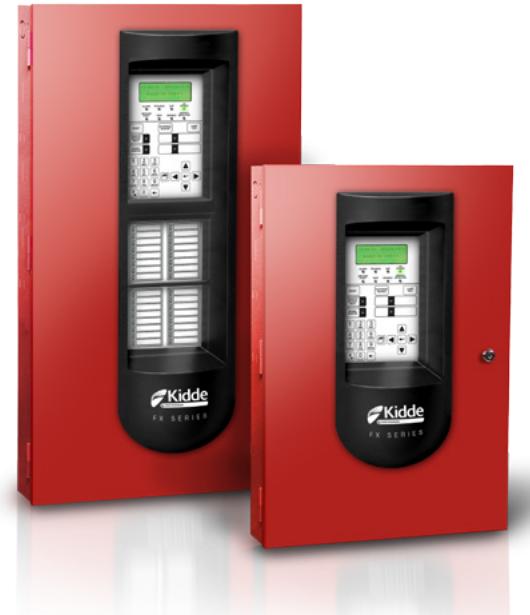
Kidde brand intelligent life safety systems offer the power of highend intelligent processing in configurations that deliver uncomplicated solutions for small to mid-sized applications. With intelligent detection, rotary addressing, automatic device mapping, optional Ethernet® connectivity, and a full line of easily-configured option cards and modules, these flexible systems offers offer versatility that benefits building owners and contractors alike.
The FX-64 provides one Class B intelligent device loop that supports up to 64 device addresses, and two Class B Notification Appliance Circuits (NACs). Optional Class A device wiring is available with the use of a module.
The FX-1000 provides one Class A or Class B intelligent device loop that supports up to 250 device addresses. Loop controller modules may be added in combination to expand total system capacity in 250-point increments to up to 1,000 device addresses. The FX-1000 panel includes four NACs that may be wired for either Class A or Class B operation.
The RZI16-2RS module adds even more capacity to FX installations by adding up to 16 conventional device circuits and two additional notification appliance circuits. This makes them an ideal retrofit solution that can accommodate new intelligent detectors, as well as existing conventional devices.
Features
- Auto-programming speeds installation time
- Form C contacts for alarm and trouble, Form A for supervisory
- Easy-to-configure rotary addressing
- Optional Ethernet port for diagnostics, programming and a variety of system reports
- Two programmable switches with LEDs and custom labeling
- Supports horn silence over two wires, and UL 1971-compliant strobe synchronization
- Class B or Class A wiring
- Ground fault detection by module
- Supports up to eight serial annunciators, (LCD, LED-only, and graphic interface)
- Can use existing wiring for most retrofit applications
- Upload/download remotely or locally
- Two-level maintenance alert reporting
- Pre-alarm and alarm verification by point
- Adjustable detector sensitivity
- 4 x 20 character backlit LCD display
- Optional earthquake hardening: seismic Importance Factor 1.5
- Standalone operation
- Transmission test frequency by hour
Application
Kidde FX Series life safety systems are powerful intelligent solutions for small to mid-sized buildings. Advanced analog technology delivers the benefits of flexible system installation, while clean and easy-to-operate user interfaces make panel operation and system maintenance quick and intuitive.
Reliability you can count on
The inherent fault-tolerant characteristics of Analog/Addressable Technology boosts the reliability of Kidde fire alarm systems. When combined with FX Series smoke and heat detectors, these systems deliver a level of dependability not previously available for small to mid-sized applications. All Kidde systems are built to exacting reliability benchmarks and meet international standards for quality, in addition to agency listings for dependability.
Flexibility built right in
Two fully-programmable front panel switch/LED combinations provide an added measure of flexibility. Their slide-in labels take the mystery out of custom applications, and present a clean finished appearance.
Perfect for retrofits
Kidde FX Series control panels are particularly well-suited to retrofit applications. All connections are made over standard wiring – no shielded cable required. This means that in most situations existing wiring can be used to upgrade a legacy control panel to FX technology without the expense or disruption of rewiring the entire building. FX control panels also support the ingenious RZI16-2RS
zone module, which adds up to 16 conventional circuits and two NACs. This combination easily accommodates new intelligent detection alongside existing conventional circuits, making it an unbeatable solution in the retrofit market.
Signals with a difference
Kidde FX Series NACs are configurable to fully support renowned Genesis Series notification appliances. When used with FX control panels these devices offer precision synchronization of strobes to UL 1971 standards — without the need for external modules. This feature also allows connected horns to be silenced while strobes on the same two-wire circuit continue to flash until the panel is reset.
Clear-cut remote annunciation
Remote annunciation is a strong suit of the FX Series fire alarm systems. Up to eight annunciators can be installed on a single system. Compatible annunciators include a range of LED and LCD models that provide zone or point annunciation, as well as common control capabilities.
FX control panels also supports graphic annunciation with optional Graphic Annunciator interface modules. Each interface provides common control, indicators, and 32 LEDs.
A complete line of accessories
FX Series life safety systems are supported by a complete line of analog/addressable detectors, modules and related equipment. Consult the Ordering Information section for details.
Programming and remote diagnostics
Kidde FX Series life safety systems are simple to set up, yet offer advanced programming features that put these small building panels into a class of their own. The auto programming feature quickly gets the panel operational using factory default settings. Basic zone and point settings can be programmed easily through the front panel interface, so the system is up and running in no time.
The FX series panels can also interface to a PC running the FX-CU configuration utility software. This option offers full system configuration in the familiar Windows® operating environment. Connection is typically made to a laptop through the panel's optional RS-232 communications port, which can also be used to connect a system printer.
Among the many innovative features of FX Series control panels is the optional network card. This module provides a standard 10/100 Base T Ethernet® network connection that permits access to the control panel from any remote location with the correct communications protocols. The connection can be used to download to the panel from the FX-CU, or upload and view system reports using the FX-CU.
Available system reports include:
- Correlation groups Device details
- Device maintenance History
- Internal status System configuration
- System status Walk test
- Dialer
Dimensions
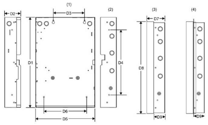
- (1) Surface Mounting Holes
- (3) Backbox with Door Attached
- (2) Semi-flush mounting Holes
- (4) Backbox with door and trim kit attached.
| Panel dimensions, in (cm) | |||||||||
|---|---|---|---|---|---|---|---|---|---|
| Model | D1* | D2 | D3 | D4 | D5* | D6 | D7 | D8 | D9 |
| FX-1000 | 28.0 | 3.85 | 9.0 | 22.0 | 15.75 | 10.25 | 3.9 | 28.2 | 2.7 |
| (71.1) | (9.8) | (22.8) | (55.8) | (40.0) | (26.0) | (9.9) | (71.6) | (6.8) | |
| FX-64 | 21.5 | 3.85 | 7.5 | 15.5 | 14.25 | 10.25 | 3.9 | 21.7 | 2.7 |
| (54.6) | (9.8) | (19.0) | (39.4) | (36.2) | (26.0) | (9.9) | (55.1) | (6.8) | |
* Add 1-1/2 in. (3.81 cm) to D1 and D5 dimensions for trim kit. The trim kit provides 0.75 inches (1.9 cm) of trim to the top, bottom, and sides of the backbox.
System Layout
FX-1000
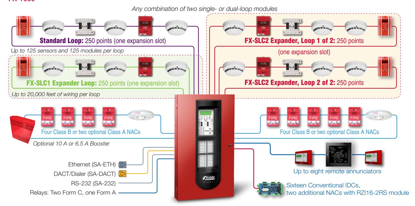
Each FX-1000 panel has room for up to two loop controller modules in any combination of single or dual 250-device loops. FX-1000 comes with one loop that supports up to 125 detectors and 125 modules.
FX-64
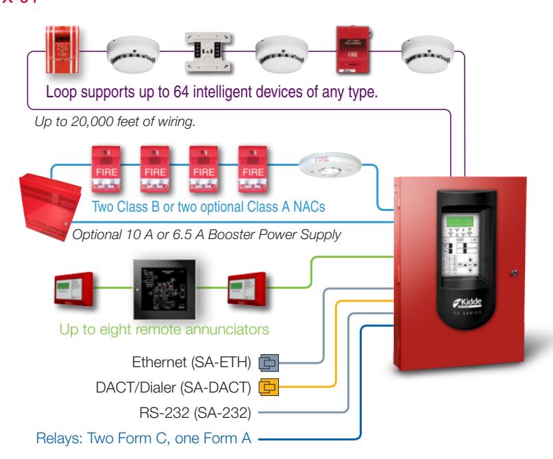
Each FX-64 panel ships with one loop controller that supports 64 devices of any type. This panel's device capacity cannot be expanded.
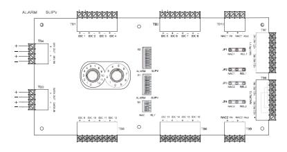
Panel Layout
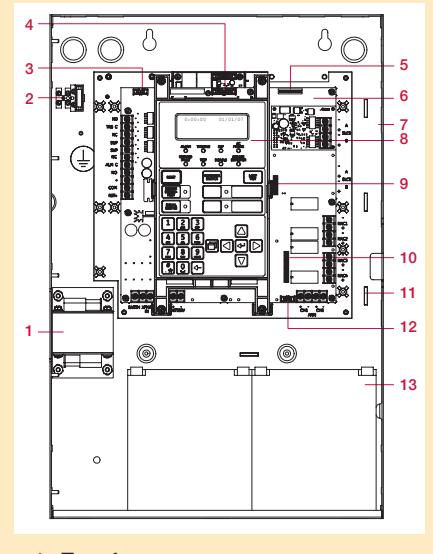
- 1 Transformer
- 2 Main AC wiring block & fuse holder
- 3 RS-232 card connector (J3)
- 4 Dialer card connection (J8)
- 5 Ethernet card connector (J1)
- 6 Main circuit board
- 7 Panel backbox enclosure
- 8 Operator interface
- 9 SLC card connector (J7)
- 10 Class A card connector (J2)
- 11 Tie wrap mounts
- 12 LED expander connector (J6)
- 13 Standby batteries
Wiring & Configuration
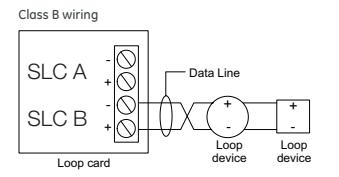
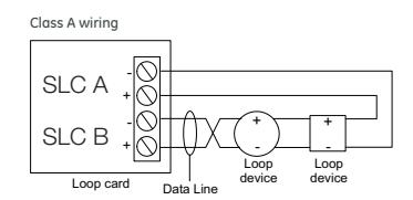
Device loop
The system provides one device loop circuit with a total capacity of 125 detectors and 125 module addresses. The loop circuit is supervised for opens, shorts, and grounds.
| Circuit specifications | FX-1000 | FX-64 |
|---|---|---|
| Device loops |
One Class B or A
loop, supporting 125 detectors and 125 modules. Expandable to four loops. |
One Class B or A loop,
supporting 64 devices of any kind. |
| Communication line voltage | Maximum 20 V peak-to-peak | |
| Circuit current | 0.5 A max | |
| Circuit impedance | 66Ω total, 0.5 μF, max | |
| Isolators | 64 maximum | |
|
Signal
Synchronization |
Supported on a system-wide basis (all device loop when using an FX-NAC addressable notification appliance circuit (NAC) module and Genesis or | |
| | ' ' | otification appliances. | |
Notification appliance circuits (TB2)
FX-1000 control panels come equipped with four notification appliance circuits. FX-64 control panels come with two NACs. Each circuit can be individually configured for continuous, temporal, synchronized, and coded output.
| Specifications | FX-1000 | FX-64 | |
|---|---|---|---|
| Circuit Type | 4 Class B or 2 Class A |
2 Class B or 2 Class A
with SA-CLA module |
|
| Voltage | 24 V | FWR | |
| Current |
6.0 A total, 2.5 A max.
per circuit at 120/230 VAC 60 Hz. 5.0 A total, 2.5 A max. per circuit at 230 VAC 50 Hz. |
3.75 A total, 2.5 A max.
per circuit at 120/230 VAC 60 Hz. 3.0 A total, 2.5 A max. per circuit at 230 VAC 50 Hz. |
|
| Impedance | 26 Ω total, 0.35 μF max | ||
| EOLR | 15 K Ω, ½ W | ||
| Synchronization | Supported system-wide | ||
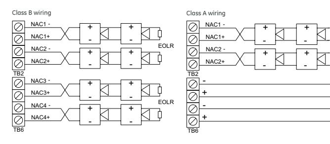
Marking indicates output signal polarity when the circuit is active. Polarity reverses when the circuit is not active. Wire notification appliances accordingly. Notification appliance polarity shown in active state.
Auxiliary & Smoke power outputs (TB3)
The control panel provides two auxiliary power outputs that can be used for powering ancillary equipment such as remote annunciators and two wire smoke detectors. Aux 2 can be software selected to operate continuously. The circuit is supervised for shorts and grounds.
| Circuit specification | ons |
|---|---|
| Circuit voltage range | 21.9 to 28.3 V |
|
Resettable circuit
(Aux power 2) |
24 VDC nominal at 500 mA Use this circuit for powering two-wire smoke detectors. |
| Continuous circuit (Aux power 1) | 24 VDC nominal at 500 mA. |
Note: Any current above 0.5 amp connected to both Aux 1 and 2 will reduce the total available NAC power by that amount.
Alarm, trouble, and supervisory relay (TB3)
The trouble relay is normally-open, held closed, and opens on any trouble event or when the panel is de-energized. The supervisory relay is normally-open, and closes on any supervisory event. The alarm relay changes over on any alarm event.
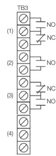
- (1) Trouble
- (2) Supervisory
- (3) Alarm
- (4) Smoke/Aux
Relay specifications
| Alarm | Trouble | Supervisory | |
|---|---|---|---|
| Type | Form C | Form A | |
| Voltage | 24 VDC at 1 A resistive | 24 VDC at | 1 A resistive |
Relay circuits can only be connected to power-limited sources.
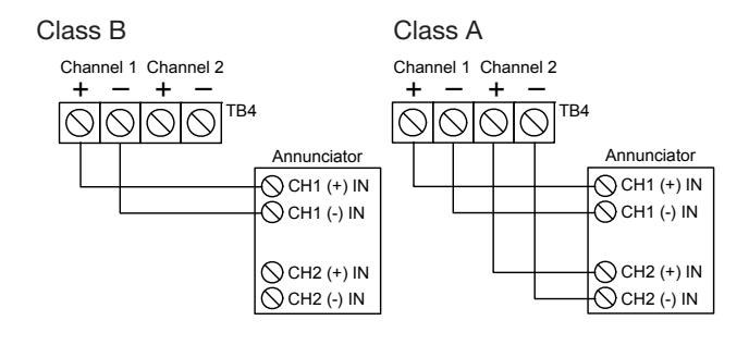
Annunciator loop (TB4)
The control panel provides a connection for up to eight serially driven and supervised remote annunciators.
Circuit specifications
| Device loops | Class B (Style Y) or Class A (Style Z) |
|---|---|
| Circuit voltage | 2.55 V |
| Circuit current | 30 mA max |
| Circuit | Up to 8 annunciators or 4000 feet |
| impedance |
Option Cards
Kidde FX Series panels are supported by a complete line of modules and related equipment that enhance performance and extend system capabilities. Option cards plug directly into the control panel main circuit board or are connected to it with a ribbon cable. After installation, terminals remain accessible. The cabinet provides ample room for wire routing, keeping wiring neat at all times.
Single and Dual Loop Controller Cards
The FX-SLC1 is a single loop controller card that can be used with the FX-64 as a replacement for the standard 64-point loop, or with the FX-1000 as a 250-point expansion module.
The FX-SLC2 is a 500-point dual loop controller card for the FX-1000 that provides two IDC circuits, each with 125 detector addresses and 125 module addresses.
| Specifications | FX-SLC1 | FX-SLC2 |
|---|---|---|
| Device Addresses | FX-1000: one loop, | FX-1000: two loops, |
| 250 device addresses | 500 device addresses | |
|
FX-64: 64 device
addresses |
||
| Wiring | Class B or Class A | |
| Operating Voltage | 24 VDC | |
| Operating Current | Standby: 55 mA | Standby: 45 mA |
| (fully loaded loop) | Alarm: 80 mA | Alarm: 70 mA |
| Note: These ratings do not include the use of two-wire smoke modules. | ||
| Communication Line | Max. 20.6 V peak-to-peak | |
| Voltage | ||
| Terminal Rating | 12 to 18 AWG (0.75 to 2.5 mm2 | ) |
| Circuit Current | 0.5 A max. | |
| Max total loop | 66 Ω | |
| resistance | ||
| Max total loop | 0.5 μF | |
| capacitance | ||
| Isolators | 64 isolators maximum per loop (total both | |
| isolator bases and modules) | ||
| Ground Fault | 0 to 5 kΩ | |
| Impedance | ||
| Operating | 32 to 120°F (0 to 49°C) | |
| Environment | 0 to 93% noncondensing at 90°F (32°C) | |
SA-ETH Ethernet Interface Card
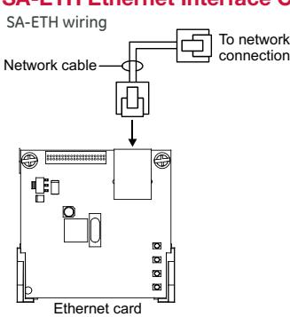
SA-ETH wiring The SA-ETH card provides a standard 10/100 Base T Ethernet network connection for connecting to an intranet, a local network, or the Internet. The card can be used to download configuration programming from the FX-CU to the panel over the network.
The Ethernet card is installed on the plastic assembly and connects to the main circuit board via a ribbon cable.
SA-ETH specifications
| Ethernet | 10/100 Base T |
| Operating environment | |
| Temperature | 32 to 120°F (0 to 49°C) |
| Humidity | 0 to 93% RH, noncondensing at 90°F |
| (32°C) |
RZI16-2RS Remote Zone Interface Module
The RZI16-2RS Addressable Remote Zone Interface Module is an addressable device that provides connections for sixteen Class B Initiating Device Circuits and two Class B Supervised Output Circuits. The inputs and outputs can be configured individually for several device types.
The device address is set using the two rotary switches located on the front of the module. The RZI16-2RS requires 18 consecutive addresses on the Signaling Line Circuit (SLC).
The RZI16-2RS incorporates two 8-segment DIP switches that are used to select the Alarm or Supervisory default device type for each of the 16 IDC circuits. The module also includes one 4-segment DIP switch used to select the default Relay or NAC output device type. Device types other than the default are accomplished through programming.
RZI16-2RS Specifications
|
Voltage
24V/Aux nominal: Supervisory current: Alarm current: 24V/Aux minimum: 24V/Aux maximum: NAC1, NAC2 nominal: |
24 VDC
250 mA at 24 VDC nominal 1000 mA 18.4 VDC 26.4 VDC 24 VDC |
| Current | |
|
Standby current
for 4.7 k EOL (U.S.) Standby current for |
4.8 mA/ circuit |
| 3.9 k EOL (Canada) | 5.7 mA/ circuit |
| Alarm current | |
| at nominal voltage | 31.1 mA/ circuit |
| Relay outputs | |
| Quantity | 2 |
| Type Rating (pilot duty) | Programmable 24 VDC at 2.5 A |
| Input circuit wiring | 25 Ω per wire |
| resistance | |
| Initiating device circuits | |
| Quantity | 16 |
| EOL resistor | 4.7 kΩ (U.S.); 3.9 kΩ Canada |
| Zone voltage | 22.78 V for 4.7 kΩ (U.S.) |
| 22.08 V for 3.9 kΩ (Canada) | |
| Alarm current | 31.1 mA/ channel at nominal voltage |
| Alarm impedance range | < 680 Ω |
| Trouble impedance range | > 5.55 kΩ |
|
Supervised output circuits
EOL resistor |
15 kΩ |
| Quantity | 2 |
| Short circuit detection | < 2.6 kΩ |
| Open circuit detection | > 61.9 kΩ |
| Contact ratings | 24 VDC at 2.5 A (5 A for two NACs) |
| Compatible cabinets | MFC(A), FX-1000, APS |
SA-DACT Dialer
The SA-DACT provides communications between the control panel and the central station over a telephone line system. It transmits system status changes (events) to a compatible digital alarm communicator receiver over the public switched telephone network. The dialer is capable of single, dual, or split reporting of events to two different account and telephone numbers. The modem feature of the SA-DACT can also be used for uploading and downloading panel configuration, history, and current status to a PC running the FX-CU.
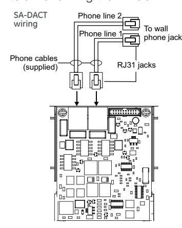
The dialer phone lines connect to connectors on the dialer's main circuit board. Phone line 1 connects to connector J4 and phone line 2 connects to connector J1.
The SA-DACT queues mes-
sages and transmits them based on priority (alarm, supervisory, trouble, and monitor). Activations are transmitted before restorations.
The SA-DACT is installed on the plastic assembly and connects to the main circuit board via a ribbon cable.
| SA-DACT specifications | |
|---|---|
| Phone line type | One or two loop-start lines on a public, |
| switched network | |
| Phone line connector | RJ-31/38X (C31/38X) |
| Communication formats | Contact ID (SIA DC-05) |
| Operating environment | |
| Temperature | 32 to 120°F (0 to 49°C) |
| Humidity | 0 to 93% RH, noncondensing at 90°F |
| (32°C) |
| Compatible DACRs | |||
|---|---|---|---|
| Receiver | Models | Formats | |
| Ademco | 685 | Contact ID | |
| FBII | CP220 | Contact ID | |
| Osborne-Hoffman | OH 2000 | Contact ID | |
| Bosch | D6600 | Contact ID | |
| Silent Knight | 9800 | Contact ID | |
| Sur-Gard | SG-MLR1, MLR2 | Contact ID | |
SA-232 RS-232 interface
SA-232 wiring The SA-232 card provides an RS-232 interface with FX panels. It can be used for connecting a printer to the control panel to print system events. The card also can be used for connecting a computer to download a configuration program from the FX-CU to the control panel.
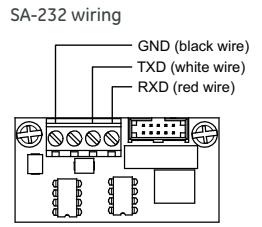
The RS-232 card is installed on the plastic assembly and connects to the main circuit board via a ribbon cable.
| SA-232 specifications | |
|---|---|
| Operating voltage | Standard EIA-232 |
| Terminal rating | 12 to18 AWG (0.75 to 2.5 sq mm) |
| Operating environment | |
| Temperature | 32 to 120°F (0 to 49°C) |
| Humidity | 0 to 93% RH, noncondensing at 90°F (32°C) |
SA-CLA Class A Module (FX-64 only)
The SA-CLA card provides Class A capability for NAC wiring. Its terminal block provides the wiring connection for NAC return wiring. The card is required for annunciator Class A wiring even though this wiring does not return to the SA-CLA card. The SA-CLA is compatible with FX-64 control panels only. FX-1000 panels are Class A Ready. The SA-CLA is installed directly to the control panel circuit board using its plastic standoffs and plug connection.
| SA-CLA specifications | |
|---|---|
| Operating voltage | 24 VFWR |
| Operating current |
3.75 A FWR total at 120/230 VAC 60 Hz
3.0 A FWR total at 230 VAC 50 Hz 2.5 A max per circuit |
| Circuit impedance | 26 ohms, 0.35uF |
| Terminal rating | 12 to18 AWG (0.75 to 2.5 sq mm) |
|
Operating environment
Temperature Humidity |
32 to 120°F (0 to 49°C)
0 to 93% RH, noncondensing at 90°F (32°C) |
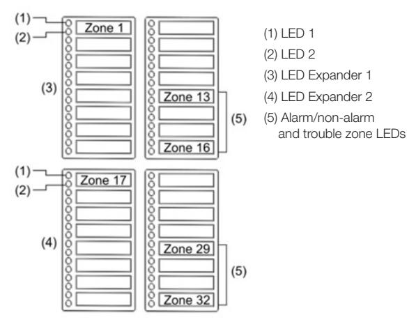
D16L-Fa LED Display Expander (FX-1000 only)
The D16L-FA LED Display Expander provides LED annunciation for up to 16 zones. It provides two LEDs for each zone. Two D16L-FA LED display expanders can be installed in each FX-1000 panel.
Specifications
| FX-64 | FX-1000 | ||
|---|---|---|---|
| Device loops |
1 loop Class B or Class A (Styles 4, 6, 7) supporting up to
64 device addresses (any combination of detectors and modules) |
1 loop, expandable to 4, Class A or B (Styles 4, 6, 7),
each loop supporting up to 250 device addresses (125 detectors and 125 modules max.). Addresses 1 to 125 are for detectors and addresses 126 to 250 are for modules |
|
|
Maximum T-taps: 63
(each device can be on its own branch) |
Maximum T-taps/loop: 124 | ||
| Notification appliance | 2 Class B (Style Y), Class A (Style Z) optional | 4 Class B (Style Y) or 2 Class A (Style Z) | |
| circuits | 3.75 A FWR total at 120/230 VAC 60 Hz | 6.0 A FWR total at 120/230 VAC 60 Hz | |
| 3.0 A FWR total at 230 VAC 50 Hz | 5.0 A FWR total at 230 VAC 50 Hz | ||
| 2.5 A FWR each max. per circuit | 2.5 A FWR each max. per circuit | ||
| Primary power | 120 VAC, 60 Hz, 1.3 A max. | 120 VAC, 60 Hz, 2.0 A max. | |
| 230 VAC, 50-60 Hz, 0.62 A max. | 230 VAC, 50-60 Hz, 0.97 A max. | ||
| Base panel current standby | 155 mA | 172 mA | |
| Base panel current alarm | 204 mA | 267 mA | |
| Input zones | 16 max. | 32 max. | |
| Remote annunciator | 8 drops max., RS-485 Class B, Class A is optional | 8 drops max., RS-485 Class A or B | |
| Data line length: 4,000 ft. (1,219 m) | Data line length: 4,000 ft. (1,219 m) | ||
| Operating voltage | 24 VDC panel | ||
|
Auxiliary power output
circuit |
Aux power 1: 500 mA, 24 VDC | ||
| Aux power 2: 500 mA, 24 VDC (1 A possible if you reduce total available NAC power by 500 mA) | |||
| Output: 28.3 to 21.9 VDC, special application | |||
| Note: For a list of compatible devices, see the FX-64 and FX-1000 Series Compatibility List (P/N 3102355-EN) | |||
| Loop circuit | Maximum loop resistance: 66 Ω | ||
| Maximum loop capacitance: 0.5 µF | |||
| Communication line voltage: Maximum 20.6 V peak-to-peak | |||
| Operating current (fully loaded loop) Stand by: 55 mA/45 mA | |||
| Alarm: 125 mA/115 mA (not including two-wire smoke modules) | |||
| Circuit current: 0.5 A max. Style 4, 6, and 7 wiring | |||
| Max. resistance between isolators: Limited only by overall wire run lengths | |||
| 64 isolators maximum per loop (total both isolator bases and modules) | |||
| Batteries | Type: Sealed lead acid | ||
| Voltage: 24 VDC | |||
| Charging current: 2.47 A max. Amp hour capacity: 26 Ah | |||
| Standby operation: 24 hour or 60 hour | |||
| 1000 control panel cabinet. If larger batteries are required, use an Kidde battery cabinet. | Placement: Up to two 10 Ah batteries will fit in the FX-64 control panel cabinet and two 18 Ah batteries will fit in the FX | ||
| SA-DACT dialer | Phone line type: One or two loop-start lines on a public, switched network | ||
| Phone line connector: RJ-31/38X (C31/38X) Communication formats: Contact ID (SIA DC-05) | |||
| Operating current Standby/Alarm: 41 mA Max.: 100 mA | |||
| FCC registration number: GESAL01BSADACT | |||
| Industry Canada Registration number: 3944A-SADACT | |||
| Ringer equivalence number: 0.1B | |||
| Ground fault impedance | 0 to 5 kΩ | ||
| Alarm contact | Form C N.O. 24 VDC at 1 A (resistive load) | ||
| Form C 24 VDC at 1 A (resistive load) | |||
| Trouble contact | |||
|
Supervisory contact
Environmental |
Form A N.O. 24 VDC at 1 A (resistive load)
Temperature: 0 to 49°C (32 to 120°F) Relative humidity: 0 to 93% noncondensing |
||

Technology that saves lives
Contact us...
Email: kidde.fire@fs.utc.com Web: Kidde.com/EngineeredSystems
Kidde is a UTC brand. 1016 Corporate Park Drive Mebane, NC 27302
© 2016 United Technologies Corporation. All rights reserved.
Ordering Information
| Part | Description |
|---|---|
| FX Fire Alarm Systems | |
| FX-1000D |
Four loop system with one 250-point loop installed, 1,000 point capacity max., includes
a two-line dialer, four NACs. Red door, surface mount enclosure. |
| FX-1000 |
Four loop system with one 250-point loop installed, 1,000 point capacity max. Four
NACs, red door, surface mount enclosure. Order dialer separately. |
| SA-TRIM2 | FX-1000 Flush mount trim, black. |
| FX-64RD |
One loop system with 64-points capacity, includes a two-line dialer, two NACs. Red
door, surface mount enclosure. |
| FX-64R |
One loop system with 64-point capacity. Two NACs, red door, surface mount enclosure.
Order dialer separately. |
| SA-TRIM1 | FX-64 Flush mount trim, black |
| Option Cards | |
| FX-SLC1 | Expansion module, one 250-device loop. |
| FX-SLC2 | Expansion module, two 250-device loops, 500 devices total. |
|
RZI16-2RS Remote Zone Interface Module. Sixteen Class B Initiating Device Circuits and two Class
B Supervised Output Circuits. Mounting bracket included. |
|
| SA-DACT | Dual Line Dialer/Modem, supports Contact ID, mounts in cabinet on base plate. |
| SA-232 | RS-232 Serial Port for connection to printers & computers, mounts in cabinet. |
| SA-ETH | Ethernet Port, Slave, mounts in cabinet on base plate. |
| SA-CLA |
Class A adapter module. Provides Class A capacity on NACs. Mounts in cabinet on
main board. FX-64 systems only. |
| D16L-FA |
LED Annunciator Module, 16 groups, 2 LEDs per group with insertable labeling. Mounts
in cabinet on FX-1000 systems only. |
| Accessories | |
| CTM |
City Tie Module. Mounts in 2-gang electric box. Provides connection to a
local energy fire alarm box. |
| MFC-A | Multifunction Fire Cabinet, 8" x 14" x 3.5" - RED. |
| MIR-PRT/S | System printer |
| BC-1 | Battery Cabinet. 14.0" x 18.25" x 7.25". Holds two 12V24A batteries. |
| BC-1R | Battery Cabinet - Red. 14.0" x 18.25" x 7.25". Holds two 12V24A batteries. |
| BC-1EQ |
Seismic hardening Kit for FX series panels. Includes battery hardening for
BC-1 enclosure and components to harden panel internal components. |
| Programming Tools | |
FX-CU FX Series configuration and diagnostics utility. 260097 RS232 cable, 4 conductor, DB9 PC interface
10-11-16