Edwards Signaling Data Sheet K85001-0641 – Ceiling Speakers Speaker-Strobes
Open the original PDF document
View PDF

Technology that saves lives
Ceiling Speakers, Speaker-Strobes
Genesis GC Series
See Specifications Section for listings details.
Overview
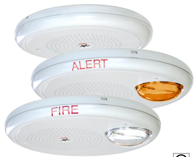
The Genesis line of ceiling life safety and emergency communications speakers and speaker-strobes combine high performance output with a low profile design to deliver a life safety signal solution that's as versatile as it is effective. While they are designed to mount inconspicuously overhead, these devices are also rated for wall-mounted applications.
Clear-lens speaker-strobes are available in high and low candela models, which feature 15 to 95, or 95 to 177 cd output (see ordering information). Ceiling speakers feature ¼ W to 2 W operation, which allows devices to be easily fine-tuned to achieve maximum benefit in exchange for the lowest possible system overhead.
Light output and wattage tap settings are selectable with conveniently-located switches. Settings remain clearly visible even after final installation, yet they are locked in place to prevent unauthorized movement after installation.
High fidelity models meet the NPFA 520 Hz requirements for newly construced commercial sleeping areas. They also produce crisp, clear voice audio output that is highly intelligible over large areas.
These low-profile appliances feature textured housings in architecturally neutral white or eye-catching life safety red. Optional ALERT or FIRE markings make them ideal for applications that require differentiation between life safety and mass notification alerts.
Standard Features
• High Fidelity 520 Hz speaker models available
Low frequency output meets NFPA standards for newly constructed commercial sleeping areas; increases sound fidelity and audio intelligibility.
• Field configurable – no need to remove the device
- Select ¼, ½, 1, or 2 watt operation
- 15/30/75/95 cd and 95/115/150/177 cd models available
- Switch settings remain visible even after the unit is installed
• Ideal for Mass Notification applications
– amber lens models available with optional ALERT markings
• Unique low-profile design
- 30 per cent slimmer profile than comparable signals
- Available with white or red housings
• Unparalleled performance
- loud 90 dBA output ensures clear, crisp audio
- Precision strobe timing meets UL synchronization standards
- 25 VRMS and 70 VRMS models available
• Easy to install
- Fits all standard 4-inch square electrical boxes with plenty of room for extra wire – no extension ring or trim plate needed
- #18 #12 AWG terminals ideal for long runs, existing wiring
• Approved for public and private mode applications
- UL 1971-listed as signaling devices for the hearing impaired
- UL 1638-listed as protective visual signaling appliances
- UL 1480-listed as life safety speaker
- UL/ULC listed for ceiling or wall use
Strobe Application
Genesis strobes are UL 1971 or 1638 listed for indoor use. Prevailing codes require strobes to be used where ambient noise conditions exceed specified levels, where occupants use hearing protection, and in areas of public accommodation. Consult with your Authority Having Jurisdiction for details.
All Genesis strobes exceed UL synchronization requirements (within 10 milliseconds over a two-hour period) when used with a synchronization source. Synchronization for multiple strobe lights in a single field of view is required. See the Specifications table for compatible synchronization sources.
Speaker Application
The suggested sound pressure level for each signaling zone used with alert or alarm signals is a minimum of 15 dB above the average ambient sound level or 5 dB above the maximum sound level having a duration of at least 60 seconds, whichever is greater. This is measured 5 feet (1.5 m) above the floor.
Doubling the distance from the signal to the ear will theoretically cause a 6 dB reduction in the received sound pressure level. The actual effect depends on the acoustic properties of materials in the space. Doubling the power output of a device (e.g.: a speaker from 1 W to 2 W) will increase the sound pressure level by 3 dBA. A 3 dBA difference represents a barely noticeable change in volume.
Combination audible/visual signals must be installed in accordance with guidelines established for strobes.
High Fidelity Models
Genesis G4HF Series High Fidelity appliances provide highly intelligible voice audio output. They are also effective in areas subject to high levels of ambient noise. These appliances are approved for use in sleeping areas under conditions described below.
Sleeping Room Applications
Genesis GCHF Series High Fidelity appliances are ideal for hotels, dormitories, and other residential occupancies where audible output must meet the 520 Hz signaling characteristics required by NFPA 72.
In sleeping areas, always ensure that the wattage tap of the speaker is set sufficiently high so that the sound pressure reaches at least 75 dBA-fast at the pillow.
These appliances are part of an end-to-end audio system approved for use in sleeping areas when used in conjunction with approved audio hardware and a factory-supplied 520 Hz tone. Check the System Compatibility List for other 520 Hz signaling requirements.
NOTE: Speakers driven by third-party audio systems are not UL approved for use in sleeping rooms.
Mass Notification Applications
Genesis Mass Notification appliances bring the same high-performance life safety features and unobtrusive design to mass notification applications. Models are available with optional ALERT housing labels, which make them ideal for applications that require
differentiation between life safety and mass notification alerts.
Application Notes - Canada
(Based in part on 1995 Canada National Building Code)
The signal sound pressure level shall not exceed 110 dBA in any normally occupied area. The sound pressure level from an audible signal in a floor area used for occupancies other than residential occupancies shall not be less than 10 dBA above ambient levels, and never less than 65 dBA. In sleeping rooms the sound pressure level from an audible signal shall not be less than 75 dBA when any intervening doors between the device and the sleeping room are closed.
Installation and Mounting
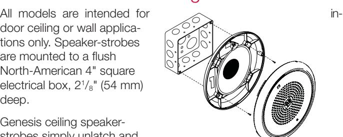
door ceiling or wall applications only. Speaker-strobes are mounted to a flush North-American 4" square electrical box, 21 /8" (54 mm) deep.
Genesis ceiling speakerstrobes simply unlatch and hinge down to open. This gains access to mounting screws and the selectable candela wattage tap switches. The shallow depth of Genesis devices leaves ample room behind the signal for extra wiring. Once installed with the cover in place, no mounting screws are visible.
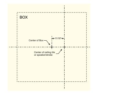
Installation Note:
When installed, these devices are not centered on the electrical box. Make
sure boxes are mounted to compensate for this difference. Use the mounting template provided with installation sheet 3100614.
Field Configuration
Genesis ceiling speakerstrobes may be set for ¼, ½, 1, or 2 watt operation. Depending on the model, Genesis ceiling speaker-strobes have multi-candela output (see ordering information).
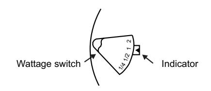
Output settings are changed by simply opening the device and sliding the switches to the desired settings. The speaker-strobe does not have to be removed to change the output settings. The settings remain visible through small windows on the front of the device after the cover is closed.
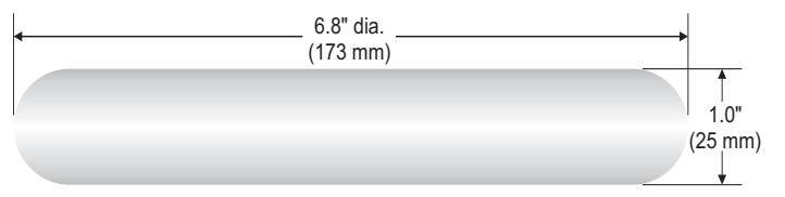
Dimensions
Typical Sound Output (dBA)
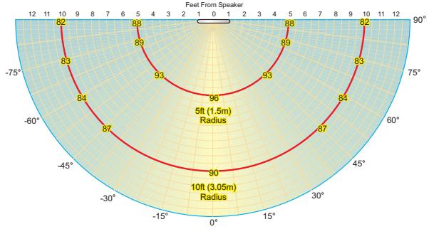
Measured at 2 watts setting in anechoic chamber
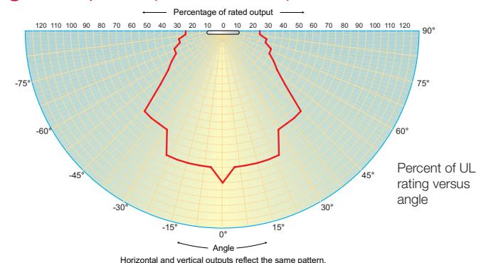
Light output - (effective cd)
|
Sound
Output |
Setting (nominal) | 5 - 1 - 1 - 1 - 1 - 1 - 1 - 1 - 1 - 1 - |
ULC-S541
Rating |
Anechoic (nominal) | |
|---|---|---|---|---|---|
| 520 Hz High Fidelity models (dBA) output at 3.05 m (10 ft.) | |||||
| 1/4 W | 0.25 W | 81.4 | 81.5 | 81 | |
| 25 | ½ W | 0.50 W | 84.5 | 84.3 | 84 |
| VRMS | 1 W | 1.00 W | 88.2 | 87.2 | 87 |
| 2 W | 2.00 W | 90.0 | 90.1 | 91 | |
| 1/4 W | 0.25 W | 81.5 | 81.9 | 81 | |
| 70 | ½ W | 0.50 W | 84.1 | 84.9 | 84 |
| VRMS | 1 W | 1.10 W | 87.9 | 87.9 | 87 |
| 2 W | 2.30 W | 90.8 | 90.8 | 91 | |
| Standard cd out | put models | |||
|---|---|---|---|---|
| Operating | VDC | 0.109 | 0.151 | |
| current, RMS (A) | VFWR | 0.131 | 0.194 | |
| Light output (cd) | Clear Lens | 15 | 30 | |
| Light output (ca) | Amber Lens | 13 | 26 | |
| High cd output r | nodels | |||
| Operating | VDC | 0.330 | 0.392 | |
| current, RMS (A) | VFWR | 0.432 | 0.518 | |
| Light output (ad) | Clear Lens | 95 | 115 | |
| Light output (cd) | Amber Lens | 82 | 100 | |
| VDC = Volts direct current, regulated and filtered | ||||
VFWR = Volts full wave rectified
Strobe Output and Current Draw
Operating currents shown above were measured at 16 VDC and 16 VFWR.
| Standar | d Hz model | s (dBA) at 3. | .05 m (10 ft.) |
|---|---|---|---|
| 1/4 W | 0.25 W | 81 | |
| 25 | ½ W | 0.50 W | 84 |
| VRMS | 1 W | 1.00 W | 87 |
| 2 W | 2.00 W | 90 | |
| 1/4 W | 0.25 W | 81 | |
|
70
VRMS |
½ W | 0.50 W | 84 |
| 1 W | 1.00 W | 87 | |
| 2 W | 2.00 W | 91 |
*Sound level output notes: dBA = Decibels, A-weighted. UL1480: Sound level output at 10 ft (3.05 m) measured in a reverberant room using 400 to 4,000 Hz band limited pink noise. ULC-S541: Meets or exceeds 85dBA in an anechoic chamber at 10 ft (3.05 m) on at least one setting per code. Directional characteristics: Within 6 dB of on-axis sound level when measured 90° off-axis (horizontal).
Current Draw
UL Nameplate Rating
|
See
note 1 |
"15" or
"D" |
"30" or
"C" |
"75" or "B" | "95" or "A' |
|---|---|---|---|---|
| RMS | RMS | RMS | RMS | |
| 16 Vdc | 109 | 151 | 281 | 318 |
| 16 Vfwr | 131 | 194 | 379 | 437 |
| UL Nam | eplate | Rating |
|---|---|---|
| (high cd | outpu | t models) |
|
"95" or
"D" |
"177" or
"A" |
|||
|---|---|---|---|---|
| RMS | RMS | RMS | RMS | |
| 330 | 392 | 502 | 565 | |
| 432 | 518 | 643 | 693 | |
Current Draw Notes
1. Light output switch settings for UL 1971 listed models are selectable by numeric candela value. ECS/MNS appliances are selectable by A, B, C, or D designations.
Candela switch setting
0.281
0.379
75
65
0.502
0.643
150
130
0.318
0.437
95
82
0.565
0.693
177 155
С
2. Current values are shown in mA.
| Typical Current | |||||||
|---|---|---|---|---|---|---|---|
|
See
note 1 |
"15" or
"D" |
"30" or
"C" |
"75" or "B" | "95" or "A" | |||
| RMS | RMS | RMS | RMS | ||||
| 16 Vdc | 94 | 140 | 273 | 325 | |||
| 20 Vdc | 74 | 108 | 205 | 244 | |||
| 24 Vdc | 63 | 90 | 168 | 194 | |||
| 33 Vdc | 48 | 70 | 124 | 139 | |||
| 16 Vfwr | 126 | 187 | 368 | 403 | |||
| 20 Vfwr | 108 | 156 | 281 | 333 | |||
| 24 Vfwr | 97 | 139 | 240 | 270 | |||
| 33 Vfwr | 89 | 119 | 197 | 214 | |||
Typical Current (high cd output models) 95 cd 150 cd 177 cd
| RMS | RMS | RMS | RMS |
|---|---|---|---|
| 333 | 392 | 499 | 551 |
| 259 | 303 | 378 | 429 |
| 212 | 245 | 306 | 342 |
| 155 | 180 | 211 | 236 |
| 484 | 570 | 673 | 724 |
| 380 | 438 | 537 | 604 |
| 318 | 361 | 434 | 484 |
| 245 | 269 | 308 | 338 |
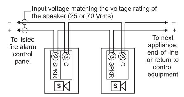
Wiring
Field wiring terminals accommodate #18 to #12 AWG (0.75 mm² to 2.5 mm²) wiring.
Specifications
| Housing |
Textured UV stabilized, color impregnated engineered plastic. Exceeds 94V-0 UL flammability rating. Red and white
models available. |
| Mounting |
Flush mount to North American 4-inch square electrical box, 2-1/8 (54 mm) inches deep, or 960A-4RF round flush box.
No extension ring required. Suitable for indoor wall or ceiling applications. |
| Wire connections | Screw terminals: polarized inputs for speaker, #18 to #12 AWG (0.75 mm² to 2.5 mm²) wire size. |
| Operating environment |
Indoor only: 32-120° F (0-49° C) ambient temperature;
0-93% relative humidity. |
|
Agency listings and
approvals, GC Models |
Meets ULC-S541, year 2004 UL requirements for standards UL1638 and UL1971. Complies with UL1480 Fifth Edition.
UL/ULC File Number: S2813. FM, MEA, CSFM approved. CSFM File Number: 7320-1657: 0211/0285. Speaker-strobes comply with ADA Code of Federal Regulation Chapter 28 Part 36 Final Rule. |
|
Agency listings and
approvals, Low Frequency GCHF Models |
UL 464 Listed for low frequency signaling applications. Meets ULC-S541, year 2004 UL requirements for standards
UL1638 and UL1971. Complies with UL1480 Fifth Edition. FM, MEA, CSFM pending. Speaker-strobes comply with ADA Code of Federal Regulation Chapter 28 Part 36 Final Rule. |
| Supervisory voltage | 30 V max. |
| Speaker | |
| Operating Voltage | 25 Vrms or 70 Vrms |
| Speaker response | 400 to 4,000 Hz |
| Output | See table on previous page. |
| Strobe | |
| Light output | Field selectable. See table on previous page. |
| Operating current | See table on previous page. |
| Strobe output rating | UL 1971, UL 1638, ULC S526: selectable 15/30/75/95 cd (VM models) and 95/115/150/177 cd (VMH models) |
| Strobe operating voltage |
16 to 33 VDC (24 VDC nominal)
or 16 to 33 VFWR (24 VFWR nominal) |
| Strobe flash rate |
One flash per second, default.
Temporal setting (private mode only): synchronized to temporal output of Genesis audible signals on same circuit. |
| Synchronization |
Meets or exceeds UL 1971 requirements. Maximum allowed resistance between any two devices is 20 Ohms. Refer
to specifications for the synchronization control module, this strobe, and the control panel to determine allowed wire resistance. |
| Synchronization Sources |
FACPs: VM and VS Series life safety systems, FX Series fire alarm control panels. Moduels: GSA-CC1S, GSA-MCC1S,
SIGA-CC2A, GSA-MCC2A, EG1M-RM. Power supplies: MIRBPS6A, MIRBPS10A, APS6A, APS10A. |
| Lens | Optical grade polycarbonate. |
Ordering Information
| Model |
High Fidelity
(520 Hz capable) |
Housing
Color |
Text
Marking |
Strobe
Output |
Speaker
Voltage |
Shipping
Weight |
|---|---|---|---|---|---|---|
| Life safety Appliances | ||||||
| GCHFRF-S2VMC | ü | Red | ||||
| GCHFWF-S2VMC | ü | FIRE | ||||
| GCF-S2VM | White | Selectable | ||||
| GC-S2VM | 15, 30, 75, or 95 cd | |||||
| GCHFRN-S2VMC | ü | Red | None | |||
| GCHFWN-S2VMC | ü | White | ||||
| GCHFRF-S2VMCH | ü | Red | ||||
| GCHFWF-S2VMCH | ü | FIRE | Selectable | |||
| GCF-S2VMH | White | 25 Volt |
1.62 lb. (0.73
kg.) |
|||
| GCHFRN-S2VMCH | ü | Red | 95, 115, 150, 177 | (Selectable | ||
| GCHFWN-S2VMCH | ü | None | ¼, ½, 1, or 2 watt) | |||
| GC-S2VMH | White | |||||
| GCHFRF-S2 | ü | |||||
| GCFR-S2 | Red | FIRE | ||||
| GCHFWF-S2 | ü | White | ||||
| GCHFRN-S2 | ü | Red | Speaker only models | |||
| GCHFWN-S2 | ü | None | ||||
| GC-S2 | White | |||||
| GCWN-S2 | ||||||
| GCHFRF-S7VMC | ü | Red | ||||
| GCHFWF-S7VMC | ü | FIRE | ||||
| GCF-S7VM | White | 15, 30, 75, or 95 cd | ||||
| GCHFRN-S7VMC | ü | Red | ||||
| GCHFWN-S7VMC | ü | White | None | |||
| GCHFRF-S7VMCH | ü | Red | ||||
| GCHFWF-S7VMCH | ü | FIRE | ||||
| GCF-S7VMH | White | 95, 115, 150, 177 | 70 V | |||
| GCHFRN-S7VMCH | ü | Red | (Selectable | |||
| GCHFWN-S7VMCH | ü | White | None | ¼, ½, 1, or 2 watt) | ||
| GCHFRF-S7 | ü | Red | ||||
| GCFR-S7 | Red | |||||
| GCHFWF-S7 | ü | FIRE | ||||
| GCF-S7 | White | Speaker only models | ||||
| GCHFRN-S7 | ü | Red | ||||
| GCHFWN-S7 | ü | None | ||||
| GC-S7 | White |

Technology that saves lives
Contact us...
Email: kidde.fire@fs.utc.com Web: <u>Kidde.com/EngineeredSystems</u>
Kidde is a UTC brand. 1016 Corporate Park Drive Mebane, NC 27302
2016 United Technologies Corporation. All rights reserved.
Ordering Information
| Model |
High
Fidelity |
Text
Marking |
Lens
Color |
Strobe
Output |
Speaker
Voltage |
Shipping
Weight |
|---|---|---|---|---|---|---|
| Mass Notification A | opliances, | white hous | ings | , | , | |
| GCHFWA-S2VMA | ✓ | AL EDT | ||||
| GCWA-S2VMA | ALERT | 13, 26, 65, | ||||
| GCHFWN-S2VMA | ✓ | Amber | or 82 cd | |||
| GCWN-S2VMA | None | |||||
| GCWN-S2VMC | ||||||
| GCHFWA-S2VMC | ✓ | Clear |
15, 30, 75,
or 95 cd |
|||
| GCWA-S2VMC | AL EDT | 01 93 Cd | 25 Volt | |||
| GCHFWA-S2VMHA | ✓ | ALERT | (Selectable | |||
| GCWA-S2VMHA | A | 82, 100, 130, | 1⁄4, 1⁄2, 1, or | |||
| GCHFWN-S2VMHA | ✓ | Amber | or 155 cd | 2 watt) | ||
| GCWN-S2VMHA | None | |||||
| GCWN-S2VMHC | ||||||
| GCHFWA-S2VMCH | ✓ | Clear |
95, 115, 150,
or 177 cd |
|||
| GCWA-S2VMHC | ALERT | OI 177 Cu | - | 1.62 lb. | ||
| GCHFWA-S2 | ✓ | ALERI | Speaker only models | |||
| GCWA-S2 | ||||||
| GCHFWA-S7VMA | ✓ | AL EDT |
13, 26, 65,
or 82 cd |
(0.73 kg.) | ||
| GCWA-S7VMA | ALERT | Amber | ||||
| GCHFWN-S7VMA | ✓ | |||||
| GCWN-S7VMA | None | |||||
| GCWN-S7VMC | ||||||
| GCHFWA-S7VMC | ✓ | Clear |
15, 30, 75,
or 95 cd |
|||
| GCWA-S7VMC | AL EDT | 01 93 Cd | 70 V | |||
| GCHFWA-S7VMAH | ✓ | ALERT | (Selectable | |||
| GCWA-S7VMHA | A l | 82, 100, 130, | 1/4, 1/2, 1, or | |||
| GCHFWN-S7VMAH | ✓ | Amber | or 155 cd | 2 watt) | ||
| GCWN-S7VMHA | None | |||||
| GCWN-S7VMHC | ||||||
| GCHFWA-S7VMCH | ✓ | Clear |
95, 115, 150,
or 177 cd |
|||
| GCWA-S7VMHC | AL EDT | or 177 ca | ||||
| GCHFWA-S7 | ✓ | ALERT | Const | or only models | ||
| GCWA-S7 | Speake | er only models |
Accessories
| EG1M-RM | Synchronization Output Module (1-gang) | 0.2 (0.1) |
|---|---|---|
| GSA-CC1S | Intelligent Synchronization Output Module (2-gang) | 0.5 (0.23) |
| GSA-MCC1S | Synchronization Output Module (Plug-in UIO) | 0.18 (0.08) |