Edwards Signaling Data Sheet K85001-0559 – Genesis Ceiling Horn-Strobes
Open the original PDF document
View PDF

Technology that saves lives
Field Configurable Ceiling Horn -Strobes
Genesis Series
One or more patents pending.
Overview
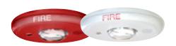
Genesis ceiling horn-strobes are small, compact, and attractive audible-visible emergency signaling devices. Protruding no more than 1.6" (41 mm), Genesis horn-strobes blend with any decor.
Thanks to patented breakthrough technology, Kidde Genesis strobes do not require bulky specular reflectors and lenses. Instead, an exclusive cavity design conditions light to produce a highly controlled distribution pattern. Significant development efforts employing this new technology have given rise to a new benchmark in strobe performance – FullLight technology.
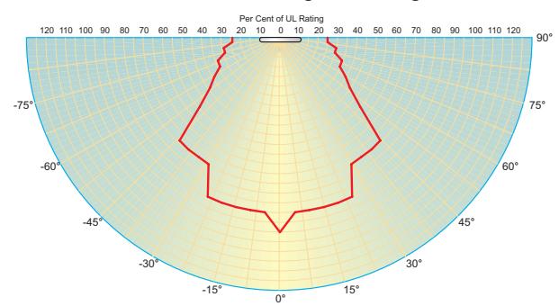
FullLight strobe technology produces a smooth light distribution pattern without the spikes and voids characteristic of specular reflectors. This ensures the entire coverage area receives consistent illumination from the strobe flash. As a result, Genesis strobes with FullLight technology go well beyond the minimum UL-required "cross" pattern.
Depending on the model, Genesis horn-strobes feature 15 to 95, or 95 to 177 candela output (see ordering information), which is selectable with a conveniently-located switch on the front of the device. The candela output setting is clearly visible even after final installation, yet it remains locked in place to prevent unauthorized movement after installation.
Genesis horn-strobes feature textured housings in architecturally neutral white or eye-catching fire alarm red. An ingenious iconographic symbol indicates the purpose of the device. This universal symbol is code-compliant and is easily recognized by all building occupants regardless of what language they speak. Models with "FIRE" markings are also available.
Standard Features
• Field configurable – no need to remove the device
- 15/30/75/95 cd and 95/115/150/177 cd models available
- Switch settings remain visible even after the unit is installed
- Low/high dB settings
• Unique low-profile design
- 30 per cent slimmer profile than comparable signals
- No visible mounting screws
- Available with white or red housings
• Easy to install
- Fits all standard 4" square electrical boxes with plenty of room behind the signal for extra wire – no extension ring or trim plate needed
- Pre-assembled with captive hardware no loose pieces
- #18 to #12 AWG terminals ideal for long runs or existing wiring
• Unparalleled performance
- Exclusive FullLight strobe technology produces the industry's most even light distribution
- Single high-efficiency microprocessor controls both horn and strobe
- Low current draw minimizes system overhead
- Independent horn control provided over a single pair of wires
- Highly regulated in-rush current allows the maximum number of strobes on a circuit
- 100 dB peak multiple frequency tone improves wall penetration
Application
Genesis strobes are UL 1971-listed for use indoors as ceiling- or wall-mounted public-mode notification appliances for the hearing impaired. Prevailing codes require strobes to be used where ambient noise conditions exceed 105 dBA (87dBA in Canada), where occupants use hearing protection, and in areas of public accommodation as defined in the Americans with Disabilities Act (see application notes – USA) .
Combination horn-strobe signals must be installed in accordance with guidelines established for strobe devices.
Strobes
Genesis strobes are UL 1971-listed for use indoors as ceiling- or wall-mounted public-mode notification appliances for the hearing impaired. Prevailing codes require strobes to be used where ambient noise conditions exceed specified levels, where occupants use hearing protection, and in areas of public accommodation. Consult with your Authority Having Jurisdiction for details.
All Genesis strobes exceed UL synchronization requirements (within 10 milliseconds other over a two-hour period) when used with a synchronization source. Synchronization is important in order to avoid epileptic sensitivity.
NOTE: The flash intensity of some visible signals may not be adequate to alert or waken occupants in the protected area. Research indicates that the intensity of strobe needed to awaken 90% of sleeping persons is approximately 100 cd. Kidde recommends that strobes in sleeping rooms be rated at at least 110 cd.
WARNING: These devices will not operate without electrical power. As fires frequently cause power interruptions, further safeguards such as backup power supplies may be required.
Horns
Genesis horn output reaches as high as 99 dB (peak) and features a unique multiple frequency tone that results in excellent wall penetration and an unmistakable warning of danger. All models may be configured for either coded or non-coded signal circuits. They can also be set for low dB output with a jumper cut that reduces horn output by about 5 dB.
The suggested sound pressure level for each signaling zone used with alert or alarm signals is at least 15 dB above the average ambient sound level, or 5 dB above the maximum sound level having a duration of at least 60 seconds, whichever is greater, measured 5 feet (1.5 m) above the floor. The average ambient sound level is, A-weighted sound pressure measured over a 24-hour period.
Doubling the distance from the signal to the ear will theoretically result in a 6 dB reduction of the received sound pressure level. The actual effect depends on the acoustic properties of materials in the space. A 3 dBA difference represents a barely noticeable change in volume.
Dimensions
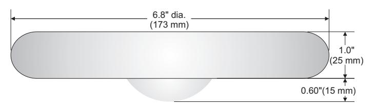
Installation and Mounting
All models are intended for indoor wall or ceiling applications only. Horn-strobes mount to any flush North-American 4" square electrical box.
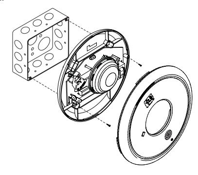
Genesis ceiling horn-strobes simply unlatch and twist to open. This gains access to mounting screws and the selectable candela switch. The shallow depth of Genesis devices leaves ample room behind the signal for extra wiring. Once installed with the cover in place, no mounting screws are visible.
Kidde recommends that these fire alarm horn-strobes always be installed in accordance with the latest recognized edition of national and local fire alarm codes.
Field Configuration
Depending on the model, Genesis horn-strobes may be set for 15 to 95, or 95 to 177 candela output (see ordering information). The output setting is changed by simply opening the device and sliding the switch to the desired setting. The horn-strobe does not have to be removed to change the output setting. The setting remains visible through a small window on the front of the device after the cover is closed.
The horn-strobe comes factory set for high dB output. Low dB output may be selected by cutting a jumper on the circuit board. This reduces the output by about 5 dB.
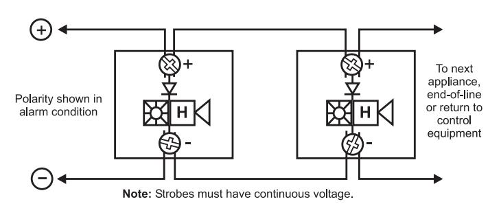
Wiring
Field wiring terminals accommodate #18 to #12 AWG (0.75 mm² to 2.5 mm²) wiring. Horn/strobes are interconnected with a single pair of wires as shown below.
Current Draw
| UL | 15 cd | 30 cd | 75 cd | 95 cd | 95 cd | 115 cd | 150 cd | 177 cd |
|---|---|---|---|---|---|---|---|---|
| Rating | RMS | RMS | RMS | RMS | RMS | RMS | RMS | RMS |
| 16 Vdc | 147 | 190 | 316 | 372 | 341 | 399 | 506 | 570 |
| 16 Vfwr | 189 | 253 | 417 | 451 | 487 | 578 | 670 | 711 |
| Typical | 15 cd | 30 cd | 75 cd | 95 cd | 95 cd | 115 cd | 150 cd | 177 cd | ||||||||
|---|---|---|---|---|---|---|---|---|---|---|---|---|---|---|---|---|
| Current | RMS | Mean | RMS | Mean | RMS | Mean | RMS | Mean | RMS | Mean | RMS | Mean | RMS | Mean | RMS | Mean |
| 16 Vdc | 111 | 95 | 152 | 143 | 281 | 276 | 333 | 328 | 324 | 322 | 377 | 374 | 477 | 474 | 554 | 551 |
| 20 Vdc | 91 | 80 | 124 | 117 | 219 | 214 | 257 | 251 | 258 | 256 | 299 | 296 | 369 | 366 | 417 | 414 |
| 24 Vdc | 80 | 71 | 108 | 101 | 185 | 180 | 212 | 207 | 220 | 217 | 252 | 249 | 304 | 301 | 341 | 338 |
| 33 Vdc | 69 | 62 | 89 | 84 | 144 | 140 | 160 | 156 | 172 | 169 | 188 | 185 | 223 | 220 | 244 | 241 |
| 16 Vfwr | 153 | 81 | 218 | 123 | 388 | 240 | 420 | 268 | 463 | 265 | 535 | 312 | 665 | 400 | 718 | 442 |
| 20 Vfwr | 141 | 70 | 190 | 100 | 325 | 188 | 378 | 219 | 392 | 211 | 439 | 240 | 517 | 287 | 587 | 334 |
| 24 Vfwr | 135 | 64 | 176 | 90 | 280 | 154 | 310 | 180 | 346 | 179 | 382 | 212 | 458 | 246 | 498 | 271 |
| 33 Vfwr | 139 | 61 | 167 | 80 | 241 | 122 | 254 | 133 | 296 | 142 | 323 | 152 | 358 | 178 | 387 | 194 |
| Typical | 15 cd | 30 cd | 75 cd | 95 cd | 95 cd | 115 cd | 150 cd | 177 cd | |||||||||
|---|---|---|---|---|---|---|---|---|---|---|---|---|---|---|---|---|---|
| Current | RMS | Mean | RMS | Mean | RMS | Mean | RMS | Mean | RMS | Mean | RMS | Mean | RMS | Mean | RMS | Mean | |
| 16 Vdc | 108 | 91 | 149 | 139 | 275 | 269 | 327 | 322 | 317 | 315 | 378 | 376 | 480 | 477 | 544 | 542 | |
| 20 Vdc | 87 | 75 | 120 | 113 | 214 | 209 | 250 | 245 | 252 | 250 | 292 | 290 | 364 | 362 | 414 | 411 | |
| 24 Vdc | 76 | 66 | 103 | 97 | 180 | 175 | 205 | 201 | 212 | 211 | 245 | 243 | 297 | 295 | 334 | 332 | |
| 33 Vdc | 64 | 57 | 85 | 80 | 138 | 135 | 153 | 150 | 159 | 157 | 181 | 179 | 215 | 213 | 234 | 232 | |
| 16 Vfwr | 141 | 76 | 204 | 118 | 384 | 239 | 418 | 265 | 461 | 265 | 521 | 305 | 656 | 396 | 705 | 432 | |
| 20 Vfwr | 127 | 65 | 176 | 95 | 312 | 181 | 371 | 214 | 381 | 208 | 437 | 242 | 508 | 285 | 576 | 326 | |
| 24 Vfwr | 118 | 60 | 162 | 82 | 262 | 149 | 301 | 171 | 335 | 172 | 370 | 195 | 440 | 235 | 485 | 264 | |
| 33 Vfwr | 127 | 56 | 155 | 73 | 229 | 118 | 249 | 129 | 285 | 134 | 308 | 149 | 349 | 169 | 373 | 186 | |
EGC-HDVM Temporal Horn-strobe: High dB Setting EGC-HDVMH High cd Temporal Horn-strobe: High dB Setting
| 15 cd | 30 cd | 75 cd | 95 cd | 95 cd | 115 cd | 150 cd | 177 cd |
|---|---|---|---|---|---|---|---|
| RMS | RMS | RMS | RMS | RMS | RMS | RMS | RMS |
| 147 | 190 | 316 | 372 | 341 | 399 | 506 | 570 |
| 189 | 253 | 417 | 451 | 487 | 578 | 670 | 711 |
EGC-HDVM Temporal Horn-strobe: High dB Setting EGC-HDVMH High cd Temporal Horn-strobe: High dB Setting
| 15 cd | 30 cd | 75 cd | 95 cd | 95 cd | 115 cd | 150 cd | 177 cd | |||||||||
|---|---|---|---|---|---|---|---|---|---|---|---|---|---|---|---|---|
| RMS | Mean | RMS | Mean | RMS | Mean | RMS | Mean | RMS | Mean | RMS | Mean | RMS | Mean | RMS | Mean | |
| 111 | 95 | 152 | 143 | 281 | 276 | 333 | 328 | 324 | 322 | 377 | 374 | 477 | 474 | 554 | 551 | |
| 91 | 80 | 124 | 117 | 219 | 214 | 257 | 251 | 258 | 256 | 299 | 296 | 369 | 366 | 417 | 414 | |
| 80 | 71 | 108 | 101 | 185 | 180 | 212 | 207 | 220 | 217 | 252 | 249 | 304 | 301 | 341 | 338 | |
| 69 | 62 | 89 | 84 | 144 | 140 | 160 | 156 | 172 | 169 | 188 | 185 | 223 | 220 | 244 | 241 | |
| 153 | 81 | 218 | 123 | 388 | 240 | 420 | 268 | 463 | 265 | 535 | 312 | 665 | 400 | 718 | 442 | |
| 141 | 70 | 190 | 100 | 325 | 188 | 378 | 219 | 392 | 211 | 439 | 240 | 517 | 287 | 587 | 334 | |
| 135 | 64 | 176 | 90 | 280 | 154 | 310 | 180 | 346 | 179 | 382 | 212 | 458 | 246 | 498 | 271 | |
| 139 | 61 | 167 | 80 | 241 | 122 | 254 | 133 | 296 | 142 | 323 | 152 | 358 | 178 | 387 | 194 | |
EGC-HDVM Temporal Horn-strobe: Low dB Setting EGC-HDVMH High cd Temporal Horn-strobe: Low dB Setting
| 15 cd | 30 cd | 75 cd | 95 cd | 95 cd | 115 cd | 150 cd | 177 cd | ||||||||
|---|---|---|---|---|---|---|---|---|---|---|---|---|---|---|---|
| RMS | Mean | RMS | Mean | RMS | Mean | RMS | Mean | RMS | Mean | RMS | Mean | RMS | Mean | RMS | Mean |
| 108 | 91 | 149 | 139 | 275 | 269 | 327 | 322 | 317 | 315 | 378 | 376 | 480 | 477 | 544 | 542 |
| 87 | 75 | 120 | 113 | 214 | 209 | 250 | 245 | 252 | 250 | 292 | 290 | 364 | 362 | 414 | 411 |
| 76 | 66 | 103 | 97 | 180 | 175 | 205 | 201 | 212 | 211 | 245 | 243 | 297 | 295 | 334 | 332 |
| 64 | 57 | 85 | 80 | 138 | 135 | 153 | 150 | 159 | 157 | 181 | 179 | 215 | 213 | 234 | 232 |
| 141 | 76 | 204 | 118 | 384 | 239 | 418 | 265 | 461 | 265 | 521 | 305 | 656 | 396 | 705 | 432 |
| 127 | 65 | 176 | 95 | 312 | 181 | 371 | 214 | 381 | 208 | 437 | 242 | 508 | 285 | 576 | 326 |
| 118 | 60 | 162 | 82 | 262 | 149 | 301 | 171 | 335 | 172 | 370 | 195 | 440 | 235 | 485 | 264 |
| 127 | 56 | 155 | 73 | 229 | 118 | 249 | 129 | 285 | 134 | 308 | 149 | 349 | 169 | 373 | 186 |
Notes and Comments
- 1. Current values are shown in mA.
- 2. UL Nameplate Rating can vary from Typical Current due to measurement methods and instruments used.
- 3. Kidde recommends using the Typical Current for system design including NAC and Power Supply loading and voltage drop calculations.
- 4. Use the Vdc RMS current ratings for filtered power supply and battery AH calculations. Use the Vfwr RMS current ratings for unfiltered power supply calculations.
- 5. Fuses, circuit breakers and other overcurrent protection devices are typically rated for current in RMS values. Most of these devices operate based upon the heating affect of the current flowing through the device. The RMS current (not the mean current) determines the heating affect and therefore, the trip and hold threshold for those devices.
- 6. Our industry has used 'mean' currents over the years. However, UL will direct the industry to use the 2004 RMS values in the future.
dBA output
| High dB | UL464 | Average | Peak | |
|---|---|---|---|---|
| Setting | Temporal | Steady |
Temporal/
Steady |
Temporal/
Steady |
| 16 Vdc | 79.8 | 83.2 | 90.6 | 93.6 |
| 24 Vdc | 83.3 | 85.4 | 93.6 | 96.6 |
| 33 Vdc | 85 | 87.8 | 95.7 | 98.7 |
| Low dB | UL464 |
Average
Peak |
|||||
|---|---|---|---|---|---|---|---|
| Setting | Temporal | Steady |
Temporal/
Steady |
Temporal/
Steady |
|||
| 16 Vdc | 75 | 79.3 | 86.3 | 88.7 | |||
| 24 Vdc | 78 | 83 | 88.8 | 92.4 | |||
| 33 Vdc | 80.9 | 85.9 | 91.8 | 95.1 | |||
Notes
1. All values shown are dBA measured at 10 feet (3.01m); 2. UL464 values measured in reverberation room; 3. Average and Peak values are measured in anechoic chamber.
Light output - (effective cd)
Percent of UL rating versus angle

Technology that saves lives
Contact us...
Email: kidde.fire@fs.utc.com Web: Kidde.com/EngineeredSystems
Kidde is a UTC brand. 1016 Corporate Park Drive Mebane, NC 27302
© 2016 United Technologies Corporation. All rights reserved.
Specifications
| Housing |
Textured UV stabilized, color impregnated engineered plastic. Exceeds 94V
0 UL flammability rating. Red and white models available. |
| Lens | Optical grade polycarbonate (clear) |
| Mounting |
North-American 4" square box, 2 1/8" (54 mm) deep (indoor wall or
ceiling applications only). |
| Wire connections |
Screw terminals: single input for both horn and strobe. #18 to #12
AWG (0.75 mm² to 2.5 mm²) wire size |
| Operating environment | Indoor: 32-120°F (0-49°C) ambient temperature. 93% relative humidity |
| Agency listings/approvals |
Meets or exceeds ULC-S525 & ULC-S526, year 2004 UL
requirements for standards UL1638 and UL1971, and complies with UL1480. All horn-strobes comply with ADA Code of Federal Regulation Chapter 28 Part 36 Final Rule. CSFM, MEA. FM pending. |
| Operating voltage |
EGC-HDVM series temporal-tone horn-strobes: non-coded, filtered
16-33 Vdc or unfiltered 16-33 Vdc FWR (or coded (audible NAC only) when used with optional EG1M Genesis Signal Master) |
| Strobe output rating |
UL 1971, UL 1638, ULC S526: selectable 15/30/75/95 cd (EGC
HDVM) and 95/115/150/177 cd (EGC-HDVMH) |
| Strobe flash rate |
EGC-HDVM series temporal-tone horn-strobes: one flash per second
synchronized with optional EG1M Genesis Signal Master indefinitely within 10 milliseconds (or self-synchronized within 200 milliseconds over thirty minutes on a common circuit without EG1M Genesis Signal Master) Temporal setting (private mode only): synchronized to temporal output of horns on same circuit |
| Synchronization Sources |
MEG1M-RM, GSA-CC1S, GSA-MCC1S, MIRMIRBPS6A,
MIRMIRBPS10A |
| Horn pulse rate |
EGC-HDVM series temporal-tone horn-strobes: temporal rate
synchronized with optional EG1M Genesis Signal Master indefinitely within 10 milliseconds (or self-synchronized within 200 milliseconds over thirty minutes on a common circuit without EG1M Genesis Signal Master) |
| Temporal audible pattern |
½ sec ON, ½ sec OFF, ½ sec ON, ½ sec OFF, ½ sec ON, 1½ sec
OFF, then repeat cycle |
Ordering Information
|
Catalog
Number |
Housing
Color |
Marking | Description |
Ship
Wt. lbs (kg) |
|---|---|---|---|---|
| EGC-HDVM | White | None | ||
| EGCF-HDVM | White | "FIRE" |
Genesis Ceiling/Wall Horn-Strobe
with selectable 15, 30, 75, or 95 cd output |
|
| EGCFR-HDVM | Red | "FIRE" |
0.82
(1.8) |
|
| EGC-HDVMH | White | None | Genesis Ceiling/Wall Horn-Strobe | |
| EGCF-HDVMH | White | "FIRE" | with selectable 95, 115, 150, or 177 cd output |
| Accessories | ||
|---|---|---|
| EG1M-RM | Genesis Signal Master – Remote Mount (1-gang) | 0.2 |
| (0.1) | ||
| 0.5 | ||
| GSA-CC1S | Intelligent Synchronization Output Module (2-gang) | (0.23) |
| 0.18 | ||
| GSA-MCC1S | Intelligent Synchronization Output Module (Plug-in UIO) | (0.08) |
White Field Configurable Ceiling Horn-Strobes may be ordered with or without optional 'FIRE' marking. Red Horn-Strobes come with 'FIRE" marking.